Note: Descriptions are shown in the official language in which they were submitted.
CA 02971141 2017-06-15
WO 2015/101707 PCT/F12014/051042
1
TOOL FOR HANDLING OF A WHEEL
FIELD OF THE INVENTION
The invention relates to a tool for handling of a wheel, especially a wheel of
a large
.. vehicle or working machine. The invention also relates to a method for
handling of
a wheel as well as to the use of the tool for removing the wheel and for
changing
the seal of the wheel.
PRIOR ART AND ITS PROBLEMS
Wheels of vehicles and working machines that are equipped with wheels need to
be regularly changed due to for example breaking or use of the wheel.
Moreover,
in large wheels typically a seal is used between the rim and the tyre, and
this 0-
ring may be necessary to change also in between changing the tyre.
Wheels are typically very tightly attached to the hub of the wheel, sometimes
even
attached by corrosion, thus significant force is needed for removing the
wheel.
Therefore it is a problem, especially for vehicles and working machines having
large wheels, that when the wheel breaks down, the vehicle or working machine
needs usually to be hauled to a repair shop for the wheel to be changed. This
then
causes costs both for the hauling and the time the vehicle or the working
machine
is out of its duty. In the field there exists thus a need for a simple and
reliable tool,
.. with which a wheel can be changed without any other additional equipment,
by a
single person.
Patent publications disclose several different tools for removing wheels. A
common point for all of them is, however, that they are only suitable for such
wheels, in which the rims are either equipped with holes into which the
removing
means can be arranged, or for rims, in which there is a groove-like outer edge
that
is visible during use.
For example in publication US 1,476,692, there is disclosed means for removing
a
wheel from a rim and for pulling the wheel out from the axle of the vehicle.
In the
CA 02971141 2017-06-15
WO 2015/101707 PCT/F12014/051042
2
disclosed means there is a middle part into which three arms have been
attached,
equipped with hooks at their ends. These hooks are arranged to the groove of
the
edge of the rim of the wheel and thereafter the threaded shank arranged in the
middle part is turned in such a manner that the rim shrinks and the tyre can
be
removed from the rim. Correspondingly, the threaded shank is turned in such a
manner that the rim expands and the wheel can be removed from the axle of the
vehicle. Publication US 3,402,455 discloses tyre remover, in which the
compression parts are pressed against each other by means of springs arranged
between them and the supporting part. Therefore, the compression is not
possible
to adjust after the tyre remover has been arranged in its place. By the same
principle works also the tyre remover, which is disclosed in publication US
1,534,350, in which the compression parts are pressed against each other by
means of turnbuckle screws. Furthermore, in both publications the angle of the
hooks in the compression ends of the compression parts is 90 , wherein tyre
removers are suitable for only a part of tyres, and the pressing force needed
is not
significant because the compression ends are mechanically stationary.
An aim of the invention is to provide a tool for removing a wheel that is
suitable
also for wheels with rims having no holes or openings. Furthermore, it is an
aim of
the invention to provide a tool, with which it is possible to change the seal
arranged between the rim and the side ring, without removing the tyre fully
from
the rim.
In this description, a tyre means a tyre arranged on a rim and mainly
manufactured
from rubber. The combination of a tyre and a rim is a wheel in this
description. The
wheel can be a wheel of any vehicle, although the tool according to the
invention
is especially suitable for handling wheels of large vehicles and working
machines.
The tool is especially advantageous for removing wheels from vehicles and
working machines equipped with wheels such as a lorry, an excavator, a
tractor, a
bucket charger, a hoist, a crane, an agricultural machine or a harvester.
BRIEF DESCRIPTION OF THE INVENTION
The invention relates to a tool for handling of a wheel, which tool comprises
a
supporting part having a first end and a second end as well as at least one
holder
CA 02971141 2017-06-15
WO 2015/101707 PCT/F12014/051042
3
arranged on the supporting part, which holder is arranged to be used in
connection
with a pushing means. Furthermore, a first compression part having a
compression end and a tension end is arranged at the first end of the
supporting
part pivotally in a plane, and a second compression part having a compression
end and a tension end is arranged at the second end of the supporting part
pivotally in a plane. A typical tool further comprises moving means for moving
the
first compression part and the second compression part in relation to the
supporting part, which means are arranged between the first compression part
and
the second compression part and into direct connection with the first
compression
part and the second compression part.
The invention also relates to a method for handling of a wheel, by using the
above
described tool, in which method the compression ends of the first and the
second
compression parts are arranged inside an edge of a rim and the moving means
are used in such a manner that the compression ends of the first and the
second
compression part move further away from each other.
The invention also relates to a use of the tool for removing a wheel from an
axle in
such a manner, that the compression ends of the first and the second
compression parts are arranged inside an edge of a rim; the moving means are
used in such a manner that the compression ends of the first and the second
compression part move further away from each other; and at least one pushing
means is used together with at least one central holder arranged on the
supporting
part, between its first end and its second end, for pushing the wheel outward
from
the axle and thereby for removing the wheel from the axle.
The invention still further relates to the use of a tool for changing a seal
between a
rim and a side ring without removing a wheel from an axle, wherein the
compression ends of the first and the second compression parts are arranged
inside an edge of the rim and the moving means are used in such a manner that
the compression ends of the first and the second compression part move further
away from each other. Thereafter at least two pushing means are used in
connection with at least two end holders arranged on the outer surface of the
supporting part, one at its first end and one at its second end, for pushing
the side
3A
ring towards the axle, for changing the seal arranged between the rim and he
side ring.
In another aspect, there is provided a tool for handling a wheel, the tool
comprising: a
supporting plate member having a first wall member and a second wall member
spaced apart
from the first wall member, the supporting wall member having a first end and
a second end,
at least one threaded holder on the supporting plate member, which threaded
holder is
configured to receive a threaded pushing mean, a first compression member
having a
compression end and a tension end, the compression end disposed between the
first wall
member and the second wall member of the supporting plate member and pivotally
connected
to the first end of the supporting plate member, a second compression member
having a
compression end and a tension end, the compression end disposed between the
first wall
member and the second wall member of the supporting plate member and pivotally
connected
to the second end of the supporting part, moving means having a first end and
a second end,
the first end connected to the tension end of the first compression member and
the second end
connected to the tension end of the second compression member, the moving
means
configured to axially move the first compression member and the second
compression
member in relation to the supporting plate member, wherein the at least one
threaded holder
comprises a first end holder connected to the first end of the supporting
member and a second
end holder connected to the second end of the supporting member.
In another aspect, there is provided a method for handling a wheel, using a
tool which
comprises: a supporting plate member having a first wall member and a second
wall member
spaced apart from the first wall member, the supporting wall member having a
first end (la)
and a second end, at least one threaded holder on the supporting plate member,
which
threaded holder is configured to receive a threaded pushing means, a first
compression
member having a compression end and a tension end, the compression end
disposed between
the first wall member and the second wall member of the supporting plate
member and
pivotally connected to the first end of the supporting plate member, a second
compression
member having a compression end and a tension end, the compression end
disposed between
the first wall member and the second wall member of the supporting plate
member and
pivotally connected to the second end of the supporting part, moving means
having a first end
and a second end, the first end connected to the tension end of the first
compression member
and the second end connected to the tension end of the second compression
member, the
moving means configured to axially move the first compression member and the
second
compression member in relation to the supporting member, wherein the at least
one threaded
CA 2971141 2019-10-08
3B
holder comprises a first end holders connected to the first end of the
supporting member and
a second end holder connected to the second end of the supporting member,
wherein the
method comprises: disposing the compression ends of the first compression part
and
compression end of the second compression part against an edge of a rim of the
wheel, and
using the moving means in such a manner that the compression end of the first
compression
part and compression end of the second compression part move further away from
each other.
Date Recue/Date Received 2021-03-30
WO 2015/101707 PCT/F12014/051042
4
BRIEF DESCRIPTION OF THE FIGURES
Figure 1 shows a tool according to an embodiment of the invention as a
perspective view.
Figure 2 shows the tool of Figure 1 as a cross-sectional view.
Figure 3 shows a detail of Figure 2.
Figure 4 shows a detail of Figure 2.
DETAILED DESCRIPTION OF THE INVENTION
The invention relates to a tool for handling of a wheel, which tool comprises
a
supporting part having a first end and a second end as well as at least one
holder
arranged on the supporting part, which holder is arranged to be used in
connection
with a pushing means. Furthermore, the tool comprises a first compression part
having a compression end and a tension end arranged at the first end of the
supporting part pivotally in a plane, and a second compression part having a
compression end and a tension end arranged at the second end of the supporting
part pivotally in a plane. A typical tool further comprises moving means for
moving
the first compression part and the second compression part in relation to the
supporting part, which means are arranged between the first compression part
and
the second compression part and into direct connection with the first
compression
part and the second compression part.
The tool according to the invention is thus suitable also for such wheels
having
rims which do not have any holes or openings, since the compression ends can
be
arranged inside the edge of the rim and thereby use the inner surface of the
rim as
a support by wedging the tool inside the rim. Then the tool can be used for
removing even large wheels from an axle (i.e. from the hub of the axle) in a
reliable and secure manner, without transporting the vehicle or working
machine to
a repair shop.
CA 2971141 2019-10-08
CA 02971141 2017-06-15
WO 2015/101707 PCT/F12014/051042
Furthermore, with the tool it is possible to change a seal arranged between
parts
of the rim, that is, between a main part of the rim and a side ring of the
rim, without
fully removing the tyre from the rim or removing the wheel from the axle, as
will be
described more in detail below. Also this operation is possible to be done
without
5 transporting the vehicle or working machine to a repair shop. Typically
the seals
need to be replaced more often than the wheels.
The supporting part is typically a longitudinal part, that can be made for
example
from a sheet. It may also be comprised of two parallel sheet-like components
that
are arranged in connection with each other, preferably at a distance from each
other. Especially preferably this distance is essentially identical to the
thickness of
the compression part, i.e. the compression parts are arranged between the two
components of the supporting part, naturally equipped with a sufficient
clearance
so that the compression parts can pivot in a plane. In this case both
components
of the supporting part are typically of the same shape and size.
The compression parts are typically also longitudinal and they are arranged
approximately perpendicular to the longitudinal axis of the supporting part.
The
compression parts are movable with respect to the supporting part, whereby the
angle between them varies between about 80 and 1000. If the supporting part
and
the compression parts are made from a sheet, the planes of their sheet
surfaces
are essentially parallel, whereby they are easily attachable to each other to
pivot in
a plane.
A first compression part having a compression end and a tension end is thus
arranged at the first end of the supporting part pivotally in a plane, and a
second
compression part having a compression end and a tension end is arranged at the
second end of the supporting part pivotally in a plane. The compression parts
are
arranged essentially at the ends of the supporting part or in the immediate
vicinity
of the ends, for example at a distance that is 5-10 % of the length of the
supporting
part. The attachment between the supporting part and the compression parts
that
pivots in a plane is done in any manner known to a person skilled in the art,
such
as with a mate pin which forms the pivoting articulation between the
supporting
part and the compression part. This attachment point forms the articulation
point.
CA 02971141 2017-06-15
WO 2015/101707 PCT/F12014/051042
6
The various parts of the tool are typically made of metal, such as steel.
Especially
the compression parts need to be strong, and they can be made for example from
a sheet-like steel, such as a steel sheet with a thickness of 30-50 mm. The
supporting part can be made also from a thinner sheet, for example from a
steel
sheet of a thickness of 5-15 mm. It is to be noted that the tool is especially
suitable
for the handling of large wheels, thus its parts need to stand also large
forces.
The moving means for moving the first compression part and the second
compression part with respect to the supporting part can be any means suitable
for this purpose. The moving can be for example perfomed in a hydraulic
manner,
for example with a jack or jacks. Especially preferably the compression parts
move
in a symmetrical manner with respect to the virtual symmetry axis of the tool.
The
virtual symmetry axis of the tool is typically perpendicular to the
longitudinal length
of the supporting part and essentially parallel to the surface of the largest
plane of
the supporting part.
According to a preferred embodiment of the invention, the moving means is a
turnbuckle screw, which is arranged between the tension end of the first
compression part and the tension end of the second compression part in such a
manner that it is essentially parallel to the supporting part. In this case,
the tool
preferably comprises also an actuator means for using the turnbuckle screw,
for
moving the parts of the turnbuckle screw with respect to each other. A
turnbuckle
screw is a device consisting of two nuts and two screw rods with opposing
threads. A turnbuckle screw can be both tightened and loosened, depending on
the direction the compression parts need to be moved. The turnbuckle screw can
be used with any suitable means, preferably with a ratchet. Preferably the
turnbuckle screw is symmetrical and it is used in its middle part, seen in its
longitudinal direction.
The moving means are arranged to the compression parts in any suitable manner,
either fixedly or removably. Typically the moving means are attached to the
compression parts at its ends. According to a preferred embodiment of the
invention, the supporting part and the moving means are substantially
parallel.
CA 02971141 2017-06-15
WO 2015/101707 PCT/F12014/051042
7
The attachment point of the moving means to the compression parts is chosen
depending on the means and their direction of use. The moving means are
attached direct to the compression parts, i.e. they are in a direct connection
with
the compression parts. The moving means can be attached to the compression
parts either in the area between the compression end and the articulation
point or
in the area between the tension end and the articulation point. When the
moving
means is a hydraulic jack, it is typically attached to the compression parts
to the
area between the compression end and the articulation point, preferably at a
distance from the compression end, When using a turnbuckle screw, it can be
attached to the compression parts either at the ends of the compression ends
or at
their immediate vicinity or alternatively at the area between the tension end
and
the articulation point, depending on the direction of use of the turnbuckle
screw.
According to a preferred embodiment, the compression ends of the first and the
second compression parts have been shaped to a hooked form in such a manner
that the hook is directed outwards from the virtual axis of symmetry of the
tool. By
a hook is meant here for example the shape of a wide U. These hooks may have
any suitable shape, while taking into account that the shape needs to be
suitable
for the structure of a typical rim as well as to be sufficiently strong (i.e.
the shape
shall not comprise parts that are too thin). One alternative shape is shown in
the
Figures, but a person skilled in the art can easily determine also other
suitable
shapes Preferably the hook has a rather sharp end, thereby it finds good
support
at the inner edge of the rim. The angle a of the hook, which is the angle
between
the axis of the the biggest length of the compression part and the hook, is
preferably less than 90 . Especially preferably this angle is 10 to 80 , for
example
25 to 45 .
Especially in the rims of the heavy transport equipment have typically not
such, in
relation to the direction of extraction, surface with 90 , in which the hook
of the tool
could be placed. If the angle is less than 90 and especially if it is a lot
of less than
90 , for example 20 to 30 , the hooks tend to slip when using the tool. Then
extraction of a tyre by known ways is not successful. In the present tool has
a
hook suitable as well as possible for the rim, whereby sufficiently strong
CA 02971141 2017-06-15
WO 2015/101707 PCT/F12014/051042
8
compression against the rim is achieved and the extraction of the tyre is
successful.
The most preferably angle is the same or a bit bigger angle than it is in the
rim in
the fastening point of the hook. In practise, the angle of the rim in the
fastening
point of the hook may slightly vary for example in the rims of different
manufacturers, but variations are typically so small that the same tool is
suitable at
least for the most rims. Often the angle of the hook is a couple of degrees
(for
example 2 to 15 ) bigger than the angle of the rim. Thus the contact occurs as
deep from the rim as possible. The angle of the hook may certainly be also
smaller than the angle of the rim, but thus the contact between the tool and
the rim
is just in the edge of the hollow of the rim, whereby the hook could slip a
bit during
the use.
Thus, the present tool solves the problem of the extraction of the wheel in
that
case that the rim has not surface to easily grasp. By means of this device the
extraction is successful even though the angle of the rim would be as small as
200
to 30 . The smallest angle in which the extraction even theoretically may be
successful is 0 .
According to another embodiment of the invention, the first compression part
is
arranged on the supporting part at a distance D from the first end of the
supporting
part, and the second compression part is arranged on the supporting part at a
distance D from the second end of the supporting part, the distance D being
chosen between 5 and 50 % of the length of the supporting part. Preferably the
supporting part is thus arranged between the centre of the length of the
compression part and its first end pivotally or rotatably. Thereby, a
compression
force as large as possible is created.
According to an embodiment, the distance D is selected between 20 and 45 % of
the lenght of the supporting part. When the distance is identical on both
compression parts, an essentially symmetrical tool and equal distribution of
force
is obtained.
CA 02971141 2017-06-15
WO 2015/101707 PCT/F12014/051042
9
According to yet another embodiment, the distance D is selected from a value
that
is between 5, 10, 15, 20, 25, 30, 35, 40, 45 and 10, 15, 20, 25, 30, 35, 40,
45, 50
% of the length of the supporting part.
According to an especially preferred embodiment, the attachment of the first
and
the second compression parts to the supporting part is arranged adjustable.
This
can be obtained for example by providing the compression part with two or more
openings, to which the supporting part is attachable. Then the location of the
supporting part with respect to the compression parts is easily adjustable for
example according to the size of the wheel to be handled.
The tool is also provided with at least one holder in the supporting part,
which
holder is arranged to be used with a pushing means. Typically, there has been
provided several of these holders, depending on the needs of use of the tool.
For
example on the outer surface of the supporting part, between its first and
second
end, at least one central holder can be arranged. Also for example two, one on
each side of the supporting part, or respectively four, two on each side of
the
supporting part, of such central holders can be arranged. The holder can be
either
an opening fixedly arranged to the supporting part itself, or a separate part
can be
attached to the supporting part, into which separate part one or more openings
has been arranged. Such a separate additional part can be detachable attached
to
the tool, whereby it can be changed.
Further, it is possible to arrange one central holder on both sides of the
supporting
part, into one or both of which two openings has been arranged, whereby the
holder can be used for the use and guiding of two or more pushing means. It is
still
possible to arrange only one holder as an additional part of the supporting
part,
which holder extends to both sides of the supporting part and into which for
example four openings have been arranged. Especially preferably the central
holder or central holders are arranged, in the longitudinal direction of the
supporting part, to its central part, such as for example in its middle or at
about a
distance of 40 % from either or both of its ends (when using more than one
holder). There can be also any other number of central holders than one or
two,
such as for example four, preferably arranged symmetrically with respect to
the
CA 02971141 2017-06-15
WO 2015/101707 PCT/F12014/051042
tool's virtual axis of symmetry. The central holder or central holders can
also be
arranged between components of the supporting part made of two parallel and
essentially identical components.
According to an embodiment the pushing means is a hydraulic jack. Such a
5 hydraulic jack can be arranged to the holder either fixedly or removably,
for
example via an opening. According to another embodiment, the holder is a
holder
with internal thread, i.e. an opening with internal thread, and the pushing
means is
a bolt equipped with an outer thread corresponding to the internal thread. The
tool
may also comprise both types of pushing means, or some other suitable pushing
10 means. This central holder or these central holders and pushing means
arranged
to them are used for removing a wheel from an axle. The pushing means can thus
be used to direct a force to a hub of the axle, whereby the wheel is removed
from
the axle. Additionally, a protective plate can be used, which plate can be
arranged
to protect the hub of the axle when removing the wheel, i.e. between the hub
and
the ends of the pushing means. Any suitable number of pushing means can be
used, depending for example on the size of the tool, such as for example one,
two,
three, four, five or six. In such a case, there are typically as many openings
arranged in the holders as there are pushing means intended to be used.
There may be arranged in the tool, in addition to or instead of the above-
mentioned central holder, at least two end holders, one at its first end and
one at
its second end. With the pushing means arranged into these end holders, of
which
there can be also for example four, two at each end, a side ring is pushed
towards
the axle (i.e. outward from the user), whereby a seal arranged between a rim
and
the side ring becomes visible, and it can be easily removed and a new seal
arranged to replace it. Thereafter the pushing means are moved to the other
direction, i.e. backwards, and the side ring moves back over the seal.
The invention also relates to a method for handling a wheel, using a tool
which
comprises
- a supporting part having a first end and a second end,
CA 02971141 2017-06-15
WO 2015/101707 PCT/F12014/051042
11
- at least one holder arranged on the supporting part, which holder is
arranged to
be used in connection with a pushing means,
- a first compression part having a compression end and a tension end,
arranged
at the supporting part pivotally in a plane,
- a second compression part having a compression end and a tension end,
arranged at the supporting part pivotally in a plane,
- moving means for moving the first compression part and the second
compression part in relation to the supporting part, which moving means are
arranged between the first compression part and the second compression part
and
into direct connection with the first compression part and the second
compression
part,
in which method the compression end of the first compression part and the
compression end of the second compression part are arranged inside an edge of
a
rim and the moving means are used in such a manner that the compression end of
the first compression part and the compression end of the second compression
part move further away from each other.
Thereby the tool directs to the rim a force, which is directed outward from
the
centre of the rim, and thus by wedging firmly secures the tool to the wheel.
When
using the tool of the invention the compression ends of the compression parts
are
first thus arranged inside an edge of a rim and after that using the moving
means
these compression ends are moved further away from each other.
The wheel can be removed from the axle by using at least one pushing means
together with at least one central holder arranged on the outer surface of the
supporting part, between its first and second ends. Thereby the wheel is
pushed
away from the axle with the pushing means and thus removed from the axle. Thus
removing a wheel is possible also on the side of a road or on a parking lot.
Preferably the hub of the axle is protected with a protective plate before
using the
pushing means.
CA 02971141 2017-06-15
WO 2015/101707 PCT/F12014/051042
12
The method according to the invention can also be used for changing a seal
arranged between a rim and a side ring without removing the wheel from an axle
and removing the tyre from the rim, in such a manner that at least two pushing
means are used in connection with two end holders arranged on the outer
surface
of the supporting part, at its first and second end, for pushing the side ring
towards
the axle, whereby the seal is exposed and it can be changed. Also this
operation
can easily be done for example at a parking lot.
The invention thus also relates to the use of a tool according to an
embodiment,
for changing a seal arranged between a rim and a side ring without removing
the
wheel from the axle, wherein the compression ends of the first and second
compression parts are arranged inside an edge of the rim and the moving means
are used in such a manner that the compression ends of the first and the
second
compression part move further away from each other. Thereafter at least two
pushing means are used in connection with at least two end holders arranged on
the outer surface of the supporting part, one at its first end and one at its
second
end, for pushing the side ring towards the axle, for changing the seal
arranged
between the rim and the side ring.
The invention also relates to a use of the tool according to an embodiment for
removing a wheel from an axle in such a manner, that the compression ends of
the first and the second compression parts are arranged inside an edge of a
rim,
the moving means are used in such a manner that the compression ends of the
first and the second compression part move further away from each other, and
at
least one pushing means is used together with at least one central holder
arranged on the supporting part, between its first end. and its second end,
for
pushing the wheel outward from the axle and thereby for removing the wheel
from
the axle.
The tool, method and uses according to the invention are suitable for the
handling
of any size of wheels, but are especially suitable for handling of a wheel of
a heavy
vehicle or a working machine equipped with wheels.
In the above description are described some embodiments of the invention. The
features according to the various embodiments can be freely combined, even if
it
CA 02971141 2017-06-15
WO 2015/101707 PCT/F12014/0510,12
13
is not expressly mentioned in this description. Similarly the characteristics
and
features described above or below in connection with the tool are suitable
also for
the method and uses, even if it is not expressly mentioned. It is furthermore
to be
noticed that reference numbers are not to be construed as limiting the claims,
and
the word "comprising" is to be interpreted as an open term.
DETAILED DESCRIPTION OF THE FIGURES
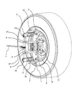
Figure 1 shows a tool according to an embodiment of the invention. A
longitudinal
supporting part 1 is shown in the Figure. At the first end la (the reference
number
is shown in Figure 2) of the supporting part is arranged, pivotally in a
plane, a first
.. compression part 2 having a compression end 2a (the reference number is
shown
in Figure 2) and a tension end 2b. At the second end lb (the reference number
is
shown in Figure 2) of the supporting part is, also pivotally in a plane,
arranged a
second compression part 2' having a compression end and a tension end 2'b.
Further, the Figure shows a turnbuckle screw 3, which is arranged at its ends
between the compression end 2b of the first compression part 2 and the
compression end 2'b of the second compression part 2' in such a manner that it
is
essentially parallel with the supporting part 1. The turnbuckle screw is at
both of its
end attached to the compression parts. Furthermore the Figure shows a ratchet,
i.e. actuator means 4 for using the turnbuckle screw, for moving the parts of
the
turnbuckle screw with respect to each other.
The Figure also shows three holders 5, 7, and 7' with internal thread arranged
on
the outer surface of the supporting part 1, of which the holder 5 is a central
holder
and the holders 7 and 7' are end holders, one at each end of the supporting
part.
In this embodiment, the central holder 5 extends to the other side of the
supporting
part, and in total four openings with internal threads have been arranged
therein.
Similarly are shown bolts 6, 6', 6" and 6" as well as 18 and 18', arranged to
be
used in connection with the holders 5, 7 and 7'.
Furthermore, Figure 1 shows the protective plate 17 of the hub of the axle,
which
is fixedly arranged to the tool via the pin 19. The protective plate can
naturally also
be a removable or separate part.
CA 02971141 2017-06-15
WO 2015/101707 PCT/F12014/051042
14
Figure 2 shows the tool of Figure 1 as a cross-section. The wheel comprises a
tyre
and a rim 11. Further is shown a side ring 12, a beadlock 13 and a seal 14,
which is an 0-ring in this embodiment. Further the Figure shows an axle 15 of
a
vehicle, a hub 16 of the axle and a protective plate 17 arranged to protect
the hub
5 16 of the axle. The Figure also shows the first end 1 a and the second
end lb of
the supporting part 1. There are two openings 8 arranged in the compression
part,
with the aid of which the position of the compression part relative to the
supporting
part can be adjusted.
Figure 3 shows details of Figure 2. Figure 3 shows the distance D, which is
the
10 distance from the first end 1 a of the supporting part to the connection
point
between the supporting part 1 and the compression part 2'. The connection
point
between the compression part and the supporting part is thus not quite at the
end
of the supporting part, but at its immediate vicinity. The Figure also shows
distance
d, i.e. the distance from the compression end 2'a of the compression part to
the
connection point between the compression part and the supporting part.
Furthermore, Figure 3 shows an angle a, which is the angle between the hook
and
the axis of the longest length of the compression part, in this embodiment
about
34 . Such a tool is applicable, for example, for rims, in which a degree of
the angle
is 22 . Figure 4 shows the side ring 12 and the seal 14 as well as the
beadlock 13
in more detail.
The tool is arranged inside the rim 11 in such a manner that the compression
ends
of the compression parts 2 and 2' are inside the inner edge of the rim, i.e.
the tool
is wedged inside the rim. Thereafter the turnbuckle screw is used in such a
manner that the compression ends move outward from the centre of the rim and
outward from each other (i.e. the turnbuckle screw is used in the Figure
upwards
and downwards from the plane of the sheet and the compression ends move in
the Figure towards right and left). Thereafter bolts 6-6" are moved towards
the
axle (downwards in the Figure), whereby, when directed to the hub of the axle
and
the protective plate 17 arranged to protect it, they push the wheel outwards
from
the axle.
CA 02971141 2017-06-15
WO 2015/101707 PCT/F12014/051042
Correspondingly, if the seal 14 is wished to be changed, the tool is wedged to
its
place and with the end holders and bolts 18, 18' the side ring 12 is pushed
outwards from the tool, whereby the seal 14 is exposed and can be changed.