Note: Descriptions are shown in the official language in which they were submitted.
PCT/CN2016/077002
ENGLISH TRANSLATION
RECHARGEABLE VACUUM CLEANER ASSEMBLY
TECHNICAL FIELD
The present disclosure relates to a technical field of vacuum cleaners, and
more particularly to a
rechargeable vacuum cleaner assembly.
BACKGROUND
In the related art, some rechargeable vacuum cleaners are equipped with a
charging stand; the
charging stand is provided with a guide rib; the vacuum cleaner defines a
groove; when the groove is
aligned with the guide rib, the vacuum cleaner may be guided to a specific
position on the charging
stand so as to be charged. However, it is not easy to align the groove with
the guide rib, resulting in a
low charging efficiency.
SUMMARY
The present disclosure seeks to solve at least one of the problems existing in
the related art to at
least some extent. An objective of the present disclosure is to provide a
rechargeable vacuum cleaner
assembly that has a high charging efficiency.
The rechargeable vacuum cleaner assembly according to the present disclosure
includes: a
rechargeable vacuum cleaner provided with a first magnetic member; and a
charging stand provided
with a second magnetic member, in which the first magnetic member is
configured to cooperate with
the second magnetic member through magnetic attraction so as to position the
rechargeable vacuum
cleaner to the charging stand.
For the rechargeable vacuum cleaner assembly according to the present
disclosure, by providing
the rechargeable vacuum cleaner assembly with the first magnetic member and
the second magnetic
member in cooperation with each other, the rechargeable vacuum cleaner may be
positioned to the
charging stand fast and accurately, thus lowering the difficulty of
positioning the rechargeable vacuum
cleaner and improving the charging efficiency.
In an example according to the present disclosure, the first magnetic member
and the second
magnetic member both are magnets.
CA 2971210 2017-08-15
PCT/CN2016/077002
ENGLISH TRANSLATION
In an example according to the present disclosure, one of the first magnetic
member and the
second magnetic member is a magnet, and the other thereof is an iron member.
In an example according to the present disclosure, the rechargeable vacuum
cleaner assembly
further includes a pedal disposed on the body and pivotable between a first
position and a second
position.
In an example according to the present disclosure, the rechargeable vacuum
cleaner assembly
further includes a safety protection device disposed on the body and normally
engaged with the pedal,
in which when the safety protection device is toggled, the safety protection
device is disengaged from
the pedal to make the pedal move from the first position to the second
position.
In an example according to the present disclosure, at least two safety
protection devices are
provided; the at least two safety protection devices are disposed on the body
and spaced apart from
each other; when the at least two safety protection devices are toggled, the
at least two safety
protection devices are disengaged from the pedal to make the pedal move from
the first position to the
second position.
In an example according to the present disclosure, each safety protection
device includes: a
safety protection member disposed at a side face of the pedal and defining an
fitting groove in which
an edge of the pedal is fitted; and a resetting member disposed between the
safety protection member
and the body, and configured to normally push the safety protection member
towards a center of the
pedal.
In an example according to the present disclosure, the safety protection
member is pivotably
connected to the body; the safety protection member has a first end and a
second end, in which the
fitting groove is defined in the second end of the safety protection member;
when the first end of the
safety protection member is toggled, the second end of the safety protection
member moves away
from the center of the pedal to disengage the edge of the pedal from the
fitting groove.
In an example according to the present disclosure, the first end of the safety
protection member
has a guide surface configured to toggle the first end of the safety
protection member.
In an example according to the present disclosure, the guide surface is
constructed to extend
obliquely towards the center of the pedal from up to down.
In an example according to the present disclosure, the guide surface is formed
as an oblique
2
CA 2971210 2017-08-15
PCT/CN2016/077002
ENGLISH TRANSLATION
plane or an oblique curved surface, extending obliquely towards the center of
the pedal from up to
down.
In an example according to the present disclosure, when the pedal is in the
first position, the first
end of the safety protection member extends out of an inner side face of the
body.
In an example according to the present disclosure, the resetting member is
configured as an
elastic sheet or a spring.
In an example according to the present disclosure, two safety protection
devices are provided and
located at a left side and a right side of the body respectively.
In an example according to the present disclosure, the pedal is disposed
horizontally when in the
first position.
In an example according to the present disclosure, a rotation angle of the
pedal 2 rotating from
the first position to the second position is denoted as a, in which a
satisfies 0 <a<60 .
In an example according to the present disclosure, a further satisfies
1'<a<100.
In an example according to the present disclosure, a top of the body is open;
the pedal is disposed
within the body and spaced apart from a bottom wall of the body.
In an example according to the present disclosure, a lower surface of the
pedal is provided with
at least one reinforcing rib.
In an example according to the present disclosure, a blade is provided in the
body, and an
opening is defined in the pedal and corresponds to a position of the blade;
when the pedal is in the
second position, the blade extends out of the opening to cut off hairs around
a brushroll of the vacuum
cleaner placed on the pedal; when the pedal is in the first position, the
blade is located below the
opening.
In an example according to the present disclosure, the charging stand for the
vacuum cleaner
further includes a microswitch disposed within the body, in which when the
pedal is in the second
position, the microswitch is triggered to make the charging stand stop
charging and rotate the
brushroll.
In an example according to the present disclosure, the blade is vertically
disposed.
In an example according to the present disclosure, the blade extends curvedly
along a length
direction thereof.
3
CA 2971210 2017-08-15
PCT/CN2016/077002
ENGLISH TRANSLATION
In an example according to the present disclosure, the blade extends in an arc
or wavy manner
along the length direction thereof.
In an example according to the present disclosure, the body has a base, and an
elastic member is
disposed between the blade and the base.
In an example according to the present disclosure, the rechargeable vacuum
cleaner assembly
further includes a blade holder disposed on the base, in which the blade is
disposed on the blade
holder; the elastic member is disposed between the blade and the blade holder
and/or between the
blade holder and the base.
In an example according to the present disclosure, when the elastic member is
disposed between
the blade holder and the base, an accommodating groove is defined in the base
and configured to
accommodate the elastic member.
In an example according to the present disclosure, an upper surface of the
elastic member is
higher than an upper surface of the base.
In an example according to the present disclosure, the elastic member is made
of soft rubber.
In an example according to the present disclosure, the pedal is provided with
a stopping piece,
and the opening is defined in the stopping piece.
In an example according to the present disclosure, the stopping piece is
horizontally disposed.
In an example according to the present disclosure, a clearance groove is
defined in a lower
surface of a part, adjacent to the opening, of the stopping piece.
In an example according to the present disclosure, a distance between an inner
wall of the
clearance groove and an upper surface of the stopping piece is gradually
decreased in a direction
towards a center of the opening.
In an example according to the present disclosure, the stopping piece is made
of soft rubber.
In an example according to the present disclosure, the pedal has a first end
and a second end, and
the first end of the pedal is pivotably connected to the body through a pivot
shaft; an elastic resetting
member is provided between the second end of the pedal and the body, and
configured to normally
push the pedal towards the first position.
In an example according to the present disclosure, a side of the body adjacent
to the second end
of the pedal is provided with a position-limiting member, and the position-
limiting member is located
4
CA 2971210 2017-08-15
PCT/CN2016/077002
ENGLISH TRANSLATION
at a side of the pedal away from the elastic resetting member.
In an example according to the present disclosure, the elastic resetting
member is configured as a
spring.
In an example according to the present disclosure, the pedal extends along a
front-rear direction;
the first end of the pedal is a rear end thereof, and the second end of the
pedal is a front end thereof.
Additional aspects and advantages of embodiments of present disclosure will be
given in part in
the following descriptions, become apparent in part from the following
descriptions, or be learned
from the practice of the embodiments of the present disclosure.
BRIEF DESCRIPTION OF THE DRAWINGS
These and/or other aspects and advantages of the present disclosure will
become apparent and
more readily appreciated from the following descriptions of embodiments made
with reference to the
drawings, in which:
Fig. 1 is a top view of a charging stand according to an embodiment of the
present disclosure;
Fig. 2 is a longitudinal sectional view of the charging stand according to the
embodiment of the
present disclosure, in which a pedal is located in a first position;
Fig. 3 is a longitudinal sectional view of the charging stand according to the
embodiment of the
present disclosure, in which the pedal is located in a second position;
Fig. 4 is a schematic view of the charging stand and a brushroll part of the
vacuum cleaner
according to the embodiment of the present disclosure;
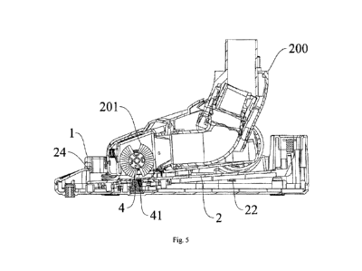
Fig. 5 is another schematic view of the charging stand and the brushroll part
of the vacuum
cleaner according to the embodiment of the present disclosure;
Fig. 6 is a transverse sectional view of the charging stand according to the
embodiment of the
present disclosure, in which a safety protection device on the left is
disengaged from the pedal and a
safety protection device on the right is engaged with the pedal;;
Fig. 7 is a top view of a charging stand according to another embodiment of
the present
disclosure;
Fig. 8 is a sectional view taken along line A-A in Fig. 7;
Fig. 9 is a front view of the charging stand shown in Fig. 7;
Fig. 10 is a sectional view taken along line B-B in Fig. 9;
5
CA 2971210 2017-08-15
PCT/CN2016/077002
' ENGLISH TRANSLATION
Fig. 11 is a schematic view of a blade and a brushroll according to an
embodiment of the present
disclosure;
Fig. 12 is another schematic view of the blade and the brushroll shown in Fig.
11;
Fig. 13 is a partial schematic view of the charging stand according to an
embodiment of the
present disclosure;
Fig. 14 is a schematic view of the vacuum cleaner, a stopping piece and the
blade according to an
embodiment of the present disclosure;
Fig. 15 is a sectional view taken along line C-C in Fig. 14;
Fig. 16 is a bottom view of the vacuum cleaner, the stopping piece and the
blade shown in Fig.
14;
Fig. 17 is a schematic view of a rechargeable vacuum cleaner assembly
according to an
embodiment of the present disclosure;
Fig. 18 is an exploded view of the rechargeable vacuum cleaner assembly shown
in Fig. 17.
Reference numerals:
100 charging stand;
1 body; 11 base; 111 accommodating groove;
2 pedal; 21 opening; 22 pivot shaft; 23 elastic resetting member; 24 position-
limiting member; 25
reinforcing rib; 26 stopping piece; 261 clearance groove;
3 safety protection device; 31 safety protection member; 311 fitting groove;
32 resetting member;
4 blade; 41 blade holder; 42 elastic member;
5 microswitch;
1011 first magnetic member; 1012 second magnetic member;
200 vacuum cleaner; 201 brushroll; 202 brushroll boss.
DETAILED DESCRIPTION
Reference will be made in detail to embodiments of the present disclosure.
Examples of the
embodiments are shown in the drawings. The same or similar elements and the
elements having same
or similar functions are denoted by like reference numerals throughout the
descriptions. The
embodiments described herein with reference to drawings are explanatory, and
used to illustrate the
6
CA 2971210 2017-08-15
PCT/CN2016/077002
ENGLISH TRANSLATION
present disclosure. The embodiments shall not be construed to limit the
present disclosure.
In the specification, it is to be understood that terms such as "central,"
"longitudinal,"
"transverse," "length," "width," "thickness," "upper," "lower," "front,"
"rear," "left," "right,"
"vertical," "horizontal," "top," "bottom," "inner," "outer," "clockwise,"
"counterclockwise," "axial,"
"radial" and "circumferential" should be construed to refer to the
orientations or positions as
described or as shown in the drawings under discussion. These relative terms
are for convenience of
description and do not indicate or imply that the device or element referred
to must have a particular
orientation or be constructed or operated in a particular orientation. Thus,
the relative terms shall not
be construed to limit the present disclosure.
In addition, terms such as "first" and "second" are used herein for purposes
of description and are
not intended to indicate or imply relative importance or significance or to
imply the number of
indicated technical features. Thus, the feature defmed with "first" and
"second" may comprise one or
more of this feature. In the description of the present disclosure, "a
plurality of' means two or more
than two, unless specified otherwise.
In the description of the present disclosure, it should be understood that,
unless specified or
limited otherwise, the terms "mounted," "connected," and "coupled" are
interpreted broadly and may
be, for example, fixed connections, detachable connections, or integral
connections; may also be
mechanical or electrical connections; may also be direct connections or
indirect connections via
intervening structures; may also be inner communications of two elements,
which can be understood
by those skilled in the art according to specific situations.
In the present disclosure, unless specified or limited otherwise, a structure
in which a first feature
is "on" or "below" a second feature may include an embodiment in which the
first feature is in direct
contact with the second feature, and may also include an embodiment in which
the first feature and
the second feature are not in direct contact with each other, but are
contacted via an additional feature
formed therebetween. Furthermore, a first feature "on," "above," or "on top
of' a second feature may
include an embodiment in which the first feature is right or obliquely "on,"
"above," or "on top of'
the second feature, or just means that the first feature is at a height higher
than that of the second
feature; while a first feature "below," "under," or "on bottom of' a second
feature may include an
embodiment in which the first feature is right or obliquely "below," "under,"
or "on bottom of' the
7
CA 2971210 2017-08-15
PCT/CN2016/077002
ENGLISH TRANSLATION
second feature, or just means that the first feature is at a height lower than
that of the second feature.
In the following, a rechargeable vacuum cleaner assembly according to
embodiments of the
present disclosure will be described with reference to Figs. 1 to 18.
As shown in Figs. 17 and 18, the rechargeable vacuum cleaner assembly
according to
embodiments of the present disclosure includes a rechargeable vacuum cleaner
and a charging stand
100. The charging stand 100 may charge the rechargeable vacuum cleaner.
The rechargeable vacuum cleaner is provided with a first magnetic member 1011,
and the
charging stand 100 is provided with a second magnetic member 1012, in which
the first magnetic
member 1011 is configured to cooperate with the second magnetic member 1012
through magnetic
attraction so as to position the rechargeable vacuum cleaner to the charging
stand 100, thereby
charging the rechargeable vacuum cleaner.
For example, referring to Fig. 2, the first magnetic member 1011 is disposed a
rear side of the
rechargeable vacuum cleaner and located at a lower portion of the rechargeable
vacuum cleaner. The
second magnetic member 1012 is disposed on the charging stand 100 and located
at a position
opposite the first magnetic member 1011. For example, the second magnetic
member 1012 may be
disposed to a body 1 of the charging stand 100. Therefore, the first magnetic
member 1011 and the
second magnetic member 1012 may cooperate conveniently through magnetic
attraction, such that the
rechargeable vacuum cleaner may be positioned to the charging stand 100 fast
and accurately, so as to
be charged, which lowers the difficulty of positioning the rechargeable vacuum
cleaner and improves
the charging efficiency. It should be noted herein that the direction "front"
refers to a direction of the
charging stand 100 close to a user, and the direction "rear" refers to an
opposite direction.
For example, when the rechargeable vacuum cleaner needs to be charged, it is
only need to make
the first magnetic member 1011 of the rechargeable vacuum cleaner approach the
second magnetic
member 1012 on the charging stand 100, such that the first magnetic member
1011 of the rechargeable
vacuum cleaner cooperates with the second magnetic member 1012 on the charging
stand 100 through
magnetic attraction, thereby guiding the rechargeable vacuum cleaner to a
charging position on the
charging stand 100 so as to charge the rechargeable vacuum cleaner. Thus, the
difficulty of positioning
the rechargeable vacuum cleaner is lowered, which brings great convenience to
the user.
For the rechargeable vacuum cleaner assembly according to the present
disclosure, by providing
8
CA 2971210 2017-08-15
PCT/CN2016/077002
ENGLISH TRANSLATION
the rechargeable vacuum cleaner assembly with the first magnetic member 1011
and the second
magnetic member 1012 in cooperation with each other, the rechargeable vacuum
cleaner may be
positioned to the charging stand 100 fast and accurately, thus lowering the
difficulty of positioning the
rechargeable vacuum cleaner and improving the charging efficiency.
In some embodiments according to the present disclosure, the first magnetic
member 1011 and
the second magnetic member 1012 both are magnets. The magnetic attraction of
the magnet is strong
and the cost thereof is low, thereby reducing the material cost of the
rechargeable vacuum cleaner
assembly.
In some other embodiments according to the present disclosure, one of the
first magnetic member
1011 and the second magnetic member 1012 is a magnet, and the other thereof is
an iron member.
That is, when the first magnetic member 1011 is a magnet, the second magnetic
member 1012 is an
iron member; when the first magnetic member 1011 is an iron member, the second
magnetic member
1012 is a magnet. Thus, it is also possible to achieve fast and accurate
positioning of the rechargeable
vacuum cleaner to the charging stand 100 and further reduce the material cost
of the rechargeable
vacuum cleaner assembly.
As shown in Figs. 1-16, the rechargeable vacuum cleaner assembly according to
embodiments of
the present disclosure further includes a pedal 2 and a safety protection
device 3. Specifically, a blade
4 is provided in the body 1 and is configured to cut off hairs or the like
around a brushroll 201 of the
vacuum cleaner 200 placed on the charging stand 100. In such a case, the
charging stand 100 not only
has a charging function but also is able to clear off hairs or the like wound
around the brushroll 201,
thereby expanding the functionality of the charging stand 100, facilitating
the cleaning of the brushroll
201, and simplifying a cleaning process of the brushroll 201. It should be
noted herein that when a
cleaning function of the charging stand 100 is applied, the vacuum cleaner 200
may be configured as a
rechargeable vacuum cleaner or other types of vacuum cleaners.
The pedal 2 is provided on the body 1 and is pivotable between a first
position and a second
position. An opening 21 is defined in the pedal and corresponds to the
position of the blade 4. When
the pedal 2 is in the first position, the blade 4 is located below the opening
21 (as shown in Fig. 2);
when the pedal 2 is in the second position, the blade 4 extends out of the
opening 21 (as shown in Fig.
3). When the pedal 2 is in the first position, the blade 4 is received in the
body and is not exposed
9
CA 2971210 2017-08-15
PCT/CN2016/077002
ENGLISH TRANSLATION
from the opening 21. At this time, the rechargeable vacuum cleaner can be
placed on the charging
stand 100 to be charged, and the safety is guaranteed when the charging stand
100 is in use. When the
pedal 2 is in the second position, the blade 4 extends out of the opening 21.
At this time, the vacuum
cleaner 200 is actuated to rotate the brushroll 201, such that the blade 4 may
cut off hairs or the like
-- wound around the brushroll 201 effectively.
One safety protection device 3 may be provided, or a plurality of safety
protection devices 3 may
be provided. When there is one safety protection device 3, the safety
protection device 3 is disposed
on the body 1 and normally engaged with the pedal 2. When the safety
protection device 3 is toggled,
the safety protection device 3 is disengaged from the pedal 2 to make the
pedal 2 move from the first
-- position to the second position.
When there are a plurality of safety protection devices 3, at least two safety
protection devices 3
are disposed on the body 1 and spaced apart from each other, and each safety
protection device 3 is
normally engaged with the pedal 2. When the at least two safety protection
devices 3 are toggled, the
at least two safety protection devices 3 are disengaged from the pedal 2 to
make the pedal 2 move
-- from the first position to the second position. In normal situations, the
safety protection devices 3 are
engaged with the pedal 2 to keep the pedal 2 in the first position, that is,
the blade 4 is located within
the body 1, which may effectively prevent a safety risk that the user may be
injured because the pedal
2 directly moves to the second position with the blade 4 exposed. Moreover,
when the hairs around
the brushroll 201 need to be cut off, all the safety protection devices 3 need
to be toggled at the same
-- time to make them disengage from the pedal 2, such that the pedal 2 is
released and then is rotated to
the second position to expose the blade 4, thereby cutting off the hairs
around the brushroll 201. In
this process, if only some of the safety protection devices 3 are toggled, the
pedal 2 cannot move to
the second position, thus further ensuring the security of the user.
For the charging stand 100 according to embodiments of the present disclosure,
with the blade 4
-- in the body 1, the functionality of the charging stand 100 is expanded, and
with the pivotable pedal 2
and the at least two safety protection devices 3, the safety may be
effectively guaranteed during
operation of the charging stand 100.
In an embodiment of the present disclosure, the pedal 2 is disposed
horizontally when in the first
position, as shown in Fig. 2, such that the overall appearance of the charging
stand 100 is aesthetic,
CA 2971210 2017-08-15
PCT/CN2016/077002
ENGLISH TRANSLATION
and the rechargeable vacuum cleaner may be horizontally placed on the pedal 2
when charged. When
the pedal 2 is in the second position, a front end of the pedal 2 is located
at a lower height compared
with the front end in the first position, as shown in Fig. 3. That is, the
pedal 2 can move to the second
position as long as the pedal 2 is stepped down, which brings great
convenience to the user. It should
be noted herein that the direction "front" refers to the direction of the
charging stand 100 close to the
user, and the direction "rear" refers to the opposite direction.
A rotation angle of the pedal 2 rotating from the first position to the second
position is denoted as
a, in which a satisfies 0 <a<60 . For example, a may be 30 . Further, a
further satisfies 1 <a<10 .
For example, a may be 3 or 5 . It could be understood that a specific value
of a may be varied
adaptively in the light of practical requirements, which will not be defined
particularly.
When the pedal 2 is in the first position, an upper end of the blade 4 is
preferably lower than a
lower surface of the pedal 2, and certainly, the upper end of the blade 4 may
be higher than the lower
surface of the pedal 2 but lower than an upper surface (not shown) of the
pedal 2.
As shown in Figs. 1 and 7, the opening 21 extends along a left-right
direction; a length direction
of the blade 4 is identical to the extension direction of the opening 21 and
identical to a length
direction of the brushroll 201. Thus, the blade 4 can fully cut off the hairs
around the brushroll 201.
Optionally, the blade 4 extends linearly along the length direction of the
blade 4, as shown in Fig.
7, such that the processing is simple and the cost is low. Certainly, the
blade 4 may extend curvedly
along the length direction thereof, such that in the hair-cutting process, the
stability of the blade 4 can
be effectively ensured, and hence the hair-cutting effect of the blade 4 is
better. For example, the blade
4 extends in an arc manner along the length direction thereof. For example,
referring to Fig. 1 in
combination with Figs. 11 to 13, the blade 4 is bent towards a direction away
from a center of the
body 1. Specifically, the blade 4 deviates from a central axis of the
brushroll 201 but is bent in a
direction towards a center of the brushroll 201, so as to cut off the hairs
wound around the brushroll
201 smoothly. Certainly, the blade 4 may extend in a wavy manner along the
length direction thereof
(not shown), such that the stability of the blade 4 may also be guaranteed
during the hair-cutting
process and the blade 4 is not easily deformed.
As shown in Fig. 13, the body 1 has a base 11, and the blade 4 is disposed on
the base 11. The
blade 4 is configured to cut off the hairs wound around the brushroll of the
vacuum cleaner. In the
CA 2971210 2017-08-15
PCT/CN2016/077002
ENGLISH TRANSLATION
hair-cutting process, the upper end of the blade 4 is in contact with a
brushroll boss 202 (not shown)
on the brushroll, so as to cut off the hairs around the brushroll boss 202. In
such a case, the vacuum
cleaner may be a rechargeable vacuum cleaner or other types of vacuum
cleaners.
Referring to Fig. 13, an elastic member 42 is disposed between the blade 4 and
the base 11, and
optionally is made of soft rubber, but is not limited thereto. Therefore,
during operation of the
charging stand 100, a height of the blade 4 may be automatically adjusted by
means of the elastic
member 42 when the blade 4 is in over-interference contact with the brushroll
boss 202 during
rotation, such that the blade 4 does not come into excessive contact with the
brushroll boss 202,
thereby greatly reducing the accuracy of positioning the blade 4, decreasing
the cost, and improving
the product qualification rate.
In some embodiments of the present disclosure, as shown in Fig. 13, the
charging stand 100
further includes a blade holder 41 that is disposed on the base 11. The blade
holder 41 is disposed on
an inner wall (a bottom wall in Fig. 2) of the base 11. The blade 4 is
disposed on the blade holder 41,
for example, may be inserted into the blade holder 41. Therefore, by providing
the blade holder 41,
the blade 4 may be mounted on the base 11 conveniently and reliably.
Preferably, the blade 4 is
disposed vertically, so as to cut off the hairs wound around the brushroll
effectively.
The elastic member 42 is disposed between the blade 4 and the blade holder 41,
and/or between
the blade holder 41 and the base 11. Specifically, the elastic member 42 may
be disposed only
between the blade 4 and the blade holder 41, or may be disposed only between
the blade holder 41
and the base 11, or may be disposed both between the blade 4 and the blade
holder 41 and between the
blade holder 41 and the base 11. For example, referring to Fig. 13, the
elastic member 42 is disposed
between the blade holder 41 and the base 11, and an upper end of the elastic
member 42 is connected
with a lower end of the blade holder 41.
Specifically, when the elastic member 42 is disposed between the blade holder
41 and the base 11,
an accommodating groove 111 is defined in the base 11 and configured to
accommodate the elastic
member 42. Referring to Fig. 13, a part of the inner wall of the base 11 is
recessed towards a direction
away from a center of the base 11, so as to define the accommodating groove
111. Thus, the elastic
member 42 may be assembled and disassembled conveniently, and the position of
the elastic member
42 may be stabilized, thereby improving the overall performance of the
charging stand 100.
12
CA 2971210 2017-08-15
PCT/CN2016/077002
= ENGLISH TRANSLATION
Optionally, an upper surface of the elastic member 42 is higher than an upper
surface of the base
11. Referring to Fig. 13, the upper surface of the elastic member 42 is higher
than an upper surface of
the bottom wall of the base 11. Thus, it is convenient to adjust the height of
the blade 4.
The pedal 2 is provided with a stopping piece 26, and the opening 21 is
defined in the stopping
piece 26. For example, referring to Figs. 14 to 16, the stopping piece 26 is
preferably disposed
adjacent to a ground brush mouth of the vacuum cleaner 200 and located below
the ground brush
mouth, in which case a distance between the stopping piece 26 and the ground
brush mouth is
relatively short. Therefore, in the hair-cutting process, the cut hairs thrown
by the brushroll 201 fall on
the stopping piece 26 and cannot exceed a dust suction range of the vacuum
cleaner 200, such that it is
possible to prevent the cut hairs from falling into any other place beyond the
dust suction range of the
vacuum cleaner 200 and hence avoid secondary pollution.
Optionally, the stopping piece 26 is horizontally disposed. The cut hairs
falling onto the stopping
piece 26 can be prevented from gathering, which facilitates suction of the
hairs on the stopping piece
26 into a dust cup by the vacuum cleaner 200, thereby improving the vacuuming
efficiency. In
addition, materials may be saved, thereby lowering the material cost.
As shown in Fig. 15, a lower surface of a part, adjacent to the opening 21, of
the stopping piece
26 defines a clearance groove 261. Further, a distance between an inner wall
of the clearance groove
261 and an upper surface of the stopping piece 26 is gradually decreased in a
direction towards a
center of the opening 21. That is, a thickness of a part of the pedal 2
adjacent to the opening 21 is
gradually reduced in a direction towards the opening 21. Thus, the blade 4 can
be prevented form
touching the stopping piece 26, the service life of the stopping piece 26 can
be prolonged, and the
usage cost can be reduced. Optionally, the stopping piece 26 may be made of
soft rubber, but is not
limited thereto. For example, the stopping piece 26 may be made of rigid
plastics, as long as the
stopping piece 26 is able to guarantee that the hairs thrown by the brushroll
201 fall within the dust
suction range of the vacuum cleaner 200, which will not be limited
specifically.
As shown in Figs. 2, 3 and 10, the lower surface of the pedal 2 is provided
with at least one
reinforcing rib 25. For example, a plurality of reinforcing ribs 25 may be
provided, and disposed to
the lower surface of the pedal 2 and spaced apart evenly. Thus, the strength
of the pedal 2 may be
guaranteed effectively by providing the reinforcing ribs 25.
13
CA 2971210 2017-08-15
PCT/CN2016/077002
' ENGLISH TRANSLATION
In an embodiment of the present disclosure, when the blade 4 extends out of
the opening 21, the
blade 4 can cut off the hairs around the brushroll 201 of the vacuum cleaner
200 placed on the pedal 2.
Referring to Fig. 9 in combination with Fig. 10, the charging stand 100
further includes a microswitch
that is disposed within the body 1. When the pedal 2 is in the second
position, the microswitch 5 is
5 triggered to make the charging stand 100 stop charging and rotate the
brushroll 201.
For example, as shown in Fig. 10, the pedal 2 is pivotably connected in the
body 1 through a
pivot shaft 22; the microswitch 5 is disposed at a rear portion of the
charging stand 100 and located
above the pedal 2. When the pedal 2 is stepped down, a rear end of the pedal 2
is tilted upwards and
triggers the microswitch 5, such that the microswitch 5 may switch off the
charging function of the
charging stand 100 to stop charging the rechargeable vacuum cleaner placed on
the pedal 2, and
transmit a signal to the rechargeable vacuum cleaner to make the vacuum
cleaner operate. At this time,
the brushroll 201 is rotated and the blade 4 implements the hair-cutting
process. It should be noted
herein that the specific structure and working principle of the microswitch 5
are well known and
hence will not be elaborated in detail.
In a specific embodiment of the present disclosure, as shown in Figs. 2 to 5,
the pedal 2 has a
first end and a second end. The first end of the pedal 2 is pivotably
connected to the body 1 through
the pivot shaft 22, and an elastic resetting member 23 is provided between the
second end of the pedal
2 and the body 1. The elastic resetting member 23 is configured to normally
push the pedal 2 towards
the first position, that is, the pedal is normally held in the first position.
Optionally, the elastic
resetting member 23 is configured as a spring.
For example, as shown in Figs. 2 to 5, the pedal 2 extends along a front-rear
direction. The first
end of the pedal 2 is the rear end thereof, and the second end of the pedal 2
is the front end thereof.
The rear end of the pedal 2 is pivotably connected to the body 1 through the
pivot shaft 22 extending
along the left-right direction. The spring is disposed at the front end of the
pedal 2 and located
between the lower surface of the pedal 2 and a bottom wall of the body 1. The
spring is configured to
normally push the pedal 2 upwards to keep the pedal 2 in a horizontal
position.
Further, a side of the body 1 adjacent to the second end of the pedal 2 is
provided with a
position-limiting member 24, and the position-limiting member 24 is located at
a side of the pedal 2
away from the elastic resetting member 23. For example, as shown in Figs. 1 to
3, the
14
CA 2971210 2017-08-15
PCT/CN2016/077002
ENGLISH TRANSLATION
position-limiting member 24 is configured as a baffle, and the baffle is
disposed at a front side of the
body 1 and abuts against the upper surface of the pedal 2, so as to prevent
the pedal 2 from rotating
upwards under the action of the spring.
As shown in Fig. 4, when the rechargeable vacuum cleaner needs to be charged,
the rechargeable
vacuum cleaner may be placed on the pedal 2 of the charging stand 100 so as to
be charged. When the
hairs need to be cut off, after the vacuum cleaner 200 (not limited to the
rechargeable vacuum cleaner
in this case) is placed onto the pedal 2, a front portion of the vacuum
cleaner 200 may be pressed
down to drive the front end of the pedal 2 to move downwards, such that the
blade 4 may extend into
the opening 21 of the pedal 2, and then the vacuum cleaner 200 is actuated to
rotate the brushroll 201
(for example, realized by means of the microswitch 5), thereby implementing
the hair-cutting process,
as shown in Fig. 5.
Therefore, by providing the charging stand 100, it is attainable to cut off
the hairs automatically,
that is, the user may implement the hair-cutting process without disassembling
the brushroll 201,
which brings great convenience to the user.
In a specific embodiment of the present disclosure, a top of the body 1 is
open; the pedal is
disposed within the body 1; the upper surface of thc pedal 2 is lower than an
upper end face of the
body 1; the pedal 2 is spaced apart from the bottom wall of the body 1; an
accommodating space is
defined between the pedal 2 and the body 1; and the blade 4, the spring and
the like may be placed in
the accommodating space.
In an embodiment of the present disclosure, as shown in Figs. 6 to 8, each
safety protection
device 3 includes a safety protection member 31 and a resetting member 32. The
safety protection
member 31 is disposed at a side face of the pedal 2, and defines a fitting
groove 311 in which an edge
of the pedal 2 is fitted. The resetting member 32 is disposed between the
safety protection member 31
and the body 1, and configured to normally push the safety protection member
31 towards a center of
the pedal 2. Optionally, the resetting member 32 is configured as a resilient
sheet or a spring. Thus, by
providing the safety protection member 31, the edge of the pedal 2 may be
fitted in the fitting groove
311 of the safety protection member 31, so as to prevent the pedal 2 from
moving to the second
position and hence prevent the blade 4 from being exposed; moreover, by
providing the resetting
member 32, when no external force is exerted on the safety protection member
31, the safety
CA 2971210 2017-08-15
PCT/CN2016/077002
ENGLISH TRANSLATION
protection member 31 enables the edge of the pedal 2 to be fitted in the
fitting groove 311 under the
action of the resetting member 32, so as to play a role of safety protection.
As shown in Fig. 6, the safety protection member 31 is pivotably connected to
the body 1, and
has a first end (e.g. an upper end in Fig. 6) and a second end (e.g. a lower
end in Fig. 6). The fitting
groove 311 is defined in the second end of the safety protection member 31.
When the first end of the
safety protection member 31 is toggled, the second end of the safety
protection member 31 moves
away from the center of the pedal 2 to disengage the edge of the pedal 2 from
the fitting groove 311.
In normal situations, the safety protection member 31 is vertically disposed,
and a side of the
fitting groove 311 towards the center of the pedal 2 is open and fitted with
the edge of the pedal 2. In
such a case, when the pedal 2 is stepped down, since the edge of the pedal 2
abuts against an inner
wall of the fitting groove 311, the pedal 2 cannot move to the second
position, i.e. the blade 4 cannot
extend out of the opening 21, which improves safety. When the hairs need to be
cut off, for example,
the first end of the safety protection member 31 may be toggled downwards,
such that the fitting
groove 311 in the second end of the safety protection member 31 moves away
from the pedal 2 and
disengaged from the pedal 2. At this time, the pedal 2 is stepped down and
hence is able to move to
the second position, such that the blade 4 extends out of the opening 21 to
implement the hair-cutting
process.
As shown in Fig. 6, when the pedal 2 is in the first position, the first end
of the safety protection
member 31 extends out of an inner side face of the body 1 and is located above
the pedal 2. Thus, it is
convenient to toggle the first end of the safety protection member 31.
Further, the first end of the safety protection member 31 has a guide surface
configured to toggle
the first end of the safety protection member 31. Optionally, the guide
surface is constructed to extend
obliquely towards the center of the pedal 2 from up to down. For example, the
guide surface is formed
as an oblique plane or an oblique curved surface, extending obliquely towards
the center of the pedal
2 from up to down. Thus, when the vacuum cleaner 200 is placed onto the
charging stand 100 from up
to down, the first end of the safety protection member 31 may be toggled
downwards by a side face of
the vacuum cleaner 200 along the guide surface, so as to disengage the pedal 2
from the safety
protection member 31.
As shown in Fig. 7, two safety protection devices 3 are provided and located
at left side and a
16
CA 2971210 2017-08-15
PCT/CN2016/077002
ENGLISH TRANSLATION
right side of the body 1 respectively. Thus, with the two safety protection
devices 3, the blade 4 may
extend out of the charging stand 100 by toggling the two safety protection
devices 3 simultaneously
and stepping down the pedal 2, such that.
An example provided with two safety protection devices 3 is illustrated
herein. When the
charging stand 100 is not used for charging, the safety protection members 31
of the two safety
protection devices 3 are engaged with the edges of the pedal 2 under the
action of the resetting
members 32, in which case even if the pedal 2 is stepped down, the pedal
cannot move to the second
position, i.e. the blade cannot extend out of the opening 21. Moreover, when
only one safety
protection device 3 is toggled and disengaged from the edge of the pedal 2,
since the other safety
protection device 3 is still engaged with the edge of the pedal 2, the pedal 2
still cannot move to the
second position, which guarantees the safety of the charging stand 100. When
the rechargeable
vacuum cleaner needs to be charged or the hairs on the vacuum cleaner 200 need
to be cut off, the
vacuum cleaner 200 may be placed on the charging stand 100. In this process,
the safety protection
members 31 of the two safety protection devices 3 are toggled by the vacuum
cleaner 200 to be
disengaged from the pedal 2, such that the rechargeable vacuum cleaner may be
charged. If the pedal
2 is stepped down and moves to the second position, the blade 4 extends out of
the opening 21 of the
pedal 2 to cut off hairs.
Therefore, by providing the safety protection device 3, when there is no need
to perform the
charging function, it is possible to avoid safety hazards when the charging
stand is accidentally
triggered.
The functionality of the charging stand 100 according to embodiments of the
present disclosure
is expanded and the safety of using the charging stand 100 is enhanced.
Other constructions and operations of the charging stand 100 according to
embodiments of the
present disclosure are well known to those skilled in the art, which will not
be elaborated herein.
Reference throughout this specification to "an embodiment," "some
embodiments," "an
exemplary embodiment," "an example," "a specific example" or "some examples"
means that a
particular feature, structure, material, or characteristic described in
connection with the embodiment
or example is included in at least one embodiment or example of the present
disclosure. Thus, the
appearances of the above phrases throughout this specification are not
necessarily referring to the
17
CA 2971210 2017-08-15
PCT/CN2016/077002
= ENGLISH TRANSLATION
same embodiment or example of the present disclosure. Furthermore, the
particular features,
structures, materials, or characteristics may be combined in any suitable
manner in one or more
embodiments or examples.
Although embodiments of the present disclosure have been shown and
illustrated, it shall be
understood by those skilled in the art that various changes, modifications,
alternatives and variants
without departing from the principle and spirit of the present disclosure are
acceptable. The scope of
the present disclosure is defined by the claims or the like.
18
CA 2971210 2017-08-15