Language selection

Search

Patent 2971506 Summary

Third-party information liability

Some of the information on this Web page has been provided by external sources. The Government of Canada is not responsible for the accuracy, reliability or currency of the information supplied by external sources. Users wishing to rely upon this information should consult directly with the source of the information. Content provided by external sources is not subject to official languages, privacy and accessibility requirements.

Claims and Abstract availability

Any discrepancies in the text and image of the Claims and Abstract are due to differing posting times. Text of the Claims and Abstract are posted:

  • At the time the application is open to public inspection;
  • At the time of issue of the patent (grant).
(12) Patent: (11) CA 2971506
(54) English Title: TIMER DEVICE AND METHOD FOR OPERATING SAID TIMER DEVICE
(54) French Title: DISPOSITIF DE TEMPORISATEUR ET PROCEDE DE FONCTIONNEMENT DUDIT DISPOSITIF DE TEMPORISATEUR
Status: Granted
Bibliographic Data
(51) International Patent Classification (IPC):
  • G04F 1/00 (2006.01)
  • G06F 11/07 (2006.01)
(72) Inventors :
  • FIORAVANTI, EMILIO (Spain)
  • GIOVANELLI, ALESSIO (Spain)
(73) Owners :
  • ZOBELE HOLDING SPA (Italy)
(71) Applicants :
  • ZOBELE HOLDING SPA (Italy)
(74) Agent: PRIMA IP
(74) Associate agent:
(45) Issued: 2023-01-31
(86) PCT Filing Date: 2014-12-19
(87) Open to Public Inspection: 2016-06-23
Examination requested: 2019-12-03
Availability of licence: N/A
(25) Language of filing: English

Patent Cooperation Treaty (PCT): Yes
(86) PCT Filing Number: PCT/EP2014/078692
(87) International Publication Number: WO2016/096034
(85) National Entry: 2017-06-19

(30) Application Priority Data: None

Abstracts

English Abstract

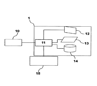
The timer device(1) comprises a first timer (12) in communication with control means(11), said control means (11) being in communication with an external component (15) and said first timer (12) sending an order to the control means (11) after a first preset time period is counted by the first timer (12), and it is characterized in that the timer device also comprises a second timer (13) in communication with said control means (11), said second timer (13) counting a second preset time period that is a portion of said first preset time period. It permits an accurate operation, even with changes of temperature and voltage and with a reduced cost.


French Abstract

Le dispositif de temporisateur (1) comprend un premier temporisateur (12) en communication avec un moyen de commande (11), ledit moyen de commande (11) étant en communication avec un composant externe (15) et ledit premier temporisateur (12) envoyant un ordre au moyen de commande (11) après qu'une première période de temps préétablie est comptée par le premier temporisateur (12), et il est caractérisé en ce que le dispositif de temporisateur comprend également un second temporisateur (13) en communication avec ledit moyen de commande (11), ledit second temporisateur (13) comptant une seconde période de temps préétablie qui est une partie de ladite première période de temps préétablie. Il permet un fonctionnement précis, même avec des changements de température et de tension, et avec un coût réduit.

Claims

Note: Claims are shown in the official language in which they were submitted.


6
CLAIMS
1. Fragrance dispenser comprising a timer device (1), said timer device (1)
comprising a first timer
(12) in communication with control means (11), said control means (11) being
in communication
.. with the fragrance dispenser (15) and said first timer (12) sending an
order to the control means
(11) after a first preset time period is counted by the first timer (12),
characterized in that the timer
device (1) also comprises a second timer (13) in communication with said
control means (11),
said second timer (13) counting a second preset time period that is a portion
of said first preset
time period, so that when said second time period is expired and said first
time period is also
expired, control means (11) of the timer device are reset, and the fragrance
dispenser (15)
connected with the timer device (1) starts a new operation cycle.
2. Fragrance dispenser according to claim 1, wherein said first timer (12) is
a watchdog timer.
3. Fragrance dispenser according to claim 1, wherein it also comprises a
memory (14) in
communication with the control means (11), which memory (14) acts as a counter
and is
incremented each time the second time period counted by the second timer (13)
expires.
4. Fragrance dispenser according to claim 1, wherein said first (12) and
second (13) timers are
placed inside the timer device (1).
5. Method for operating the fragrance dispenser according to any one of claims
1-4, characterized
in that it comprises the following steps:
- set a first time period to be counted by a first timer (12);
- set a second time period to be counted by a second timer (13), said second
time period being a
portion of the first time period;
- when said second time period is expired, but said first time period is not
expired, the second
timer (13) begins again the measure of the second time period; and
Date Recue/Date Received 2021-07-30

7
- when said second time period is expired and said first time period is also
expired, control means
(11) of the timer device are reset, and the fragrance dispenser (15) connected
with the timer
device (1) starts a new operation cycle.
6. Method according to claim 5, wherein when the second time period is expired
but the first time
period is not expired, the value of a memory (14) is incremented, and when
said second time
period is expired and said first time period is also expired the value of the
memory (14) is read
and it is used to calculate a new time base, which is used as the first time
period for the next
operation cycle.
Date Recue/Date Received 2021-07-30

Description

Note: Descriptions are shown in the official language in which they were submitted.


CA 02971506 2017-06-19
WO 2016/096034 PCT/EP2014/078692
1
TIMER DEVICE AND METHOD FOR OPERATING SAID TIMER DEVICE
DESCRIPTION
The present invention refers to a timer device and to a method for operating
said
timer device.
Background of the invention
The timer devices based on microprocessors or microcontrollers are used to
control
a huge number of electronic and' electromechanical devices in a wide range of
environmental and temperature conditions, using different power supply
methods,
from a very stable power supply until batteries.
The main problem to solve for the development of low cost battery powered
devices,
including fragrance, soap and insecticide dispensers with a timer device
comprising
one control unit is the consumption control.
A typical method used is to place a control unit in sleeping mode when it is
not used,
and periodically in an awakening mode in order to allow it to check for some
scheduled activities.
The sleep mode reduces the activity of the control unit and its related
consumptions
near zero. This awakening mode can be accomplished using a particular timer
present inside the control unit, and if it is not cleared before it expires,
resets the
control unit.
However, in these timer devices there are two problems that reduce the timing
precision: the voltage and temperature variations affect the accuracy of the
internal
timers of the control unit, with a consequently variation of the timing
generated by
them, and the timer usually used is less accurate than other timers.
Since the timing generation is one of the keys of any control system, the
accuracy
used to accomplish them is essential for a correct operation of the timer
device.

CA 02971506 2017-06-19
WO 2016/096034 PCT/EP2014/078692
2
Alternative solutions, useful for low cost devices and able to produce an
adequately
timing require a circuitry external to the control unit. This circuitry
increases the cost
and complexity of the device, and reduces the number of the available ports on
the
control unit, normally reduced in the low cost control units.
Therefore, it is evident the need of a timer device and method that permits an

accurate operation, even with changes of temperature and voltage and with a
reduced cost.
Description of the invention
With the timer device and the method according to the invention said drawbacks
can
be solved, presenting other advantages that will be described hereinafter.
The timer device according to the present invention comprises a first timer in
communication with control means, said control means being in communication
with
an external component and said first timer sending an order to the control
means
after a first preset time period is counted by the first timer, and it is
characterized in
that the timer device also comprises a second timer in communication with said
control means, said second timer counting a second preset time period that is
a
portion of said first preset time period.
According to a preferred embodiment, said first timer is a watchdog timer.
Furthermore, the timer device according to the present invention preferably
also
comprises a memory in communication with the control means, which memory acts
as a counter and is incremented each time the second time period counted by
the
second timer expires.
Advantageously, said first and second timers are placed inside the timer
device, i.e.
the second timer is not independent from the timer device.
According to second aspect, the present invention also refers to a method for
operating the timer device as described previously, and it comprises the
following

CA 02971506 2017-06-19
WO 2016/096034 PCT/EP2014/078692
3
steps:
- set a first time period to be counted by a first timer;
- set a second time period to be counted by a second timer, said second time
period
being a portion of the first time period;
- when said second time period is expired, but said first time period is not
expired,
the second timer begins again the measure of the second time period; and
- when said second time period is expired and said first time period is also
expired,
control means of the timer device are reset, and a component connected with
the
timer device starts an operation cycle.
In the method according to the present invention, preferably when the second
time
period is expired but the first time period is not expired, the value of a
memory is
incremented, and when said second time period is expired and said first time
period
is also expired the value of the memory is read and it is used to calculate a
new time
base, which is used as the first time period for the next operation cycle.
According to the present invention, it is provided a timer device and method
that
permits an accurate operation, even with changes of temperature and voltage
and
with a reduced cost.
Brief description of the drawings
For a better understanding of what has been disclosed, some drawings are
attached
in which, diagrammatically and only as a non-limitative example a specific
embodiment is shown.
Fig. 1 is a block diagram of the timer device according to the present
invention.
Description of a preferred embodiment

CA 02971506 2017-06-19
WO 2016/096034 PCT/EP2014/078692
4
Fig. 1 shows a block diagram of the timer device 1 according to the present
invention, comprising a first timer 12, preferably a watchdog timer, in
communication
with control means 11, said control means 11 being in communication with an
external component 15 and said first timer 12 sends an order to the control
means
11 after a first preset time period is counted by the first timer 12. It must
be pointed
out that the control means 11 are fed by a power source 10.
The timer device according to the invention also comprises a second timer 13
in
communication with said control means 11, said second timer 13 counting a
second
preset time period that is a portion of said first preset time period.
The timer device according to the invention also comprises a memory 14 in
communication with the control means 11, which memory 14 acts as a counter and

is incremented each time the second time period counted by the second timer 13
expires, as will be explained hereinafter.
As shown in Fig. 1, said first 12 and second 13 timers are placed inside the
timer
device 1, so that the second timer 13 is not an external element.
Firstly, it must be pointed out that "operation cycle" is considered all
activities done
by the control means 11 in order to follow what the software requires for the
component 15. If the component 15 is a fragrance dispenser, the normal
operations
are the temporized activation/deactivation of the heater or fan, the led
blinks,
checking for the button activation and change the device status consequently,
and
soon.
The method according to the invention comprises the following steps:
- set a first time period to be counted by a first timer 12 and a second time
period to
be counted by a second timer 13, said second time period being a portion of
the first
time period;
- when said second time period is expired, but said first time period is not
expired,
the second timer 13 begins again the measure of the second time period; and

CA 02971506 2017-06-19
WO 2016/096034 PCTTEP2014/078692
- when said second time period is expired and said first time period is also
expired,
control means 11 of the timer device are reset, and a component 15 connected
with
the timer device 1 starts a new operation cycle.
5 Preferably, when the second time period is expired but the first time
period is not
expired, the value of a memory 14 is incremented, and when said second time
period is expired and said first time period is also expired the value of the
memory
14 is read and it is used to calculate a new time base, which is used as the
first time
period for the next operation cycle.
One example of a component is a fragrance dispenser, in which an operation
cycle
is defined and which is repeated cyclically, for example activating a heater
or fan for
dispensing the fragrance and then deactivating said heater or fan.
In this case, the first time period can be of 10 seconds, which will be
counted by the
first timer 12 and the second time period can be 500 milliseconds, which will
be
counted by the second timer 13.
When the first 500 milliseconds are counted by the second timer 13 and the
second
time period is the count of the memory 14, originally 0, will be increased by
1,
because the first time period will not be expired.
This count of the second time period will be repeated 20 times, until the
expiration of
the first time period, 10 seconds after. At this time, the control means 11
will be
reset, the value of the memory (in this case 20) will be read, and this value
will be
used as a basis for calculating a new time base, which will be used as the
first time
' period for the next operation cycle.
Even though reference is made to a specific embodiment of the invention, it is
apparent for a person skilled in the art that the timer device and the method
are
susceptible of numerous variations and modifications, and all the details
cited can
be substituted by other technically equivalent ones, without departing from
the
scope of protection defined by the attached claims.

Representative Drawing
A single figure which represents the drawing illustrating the invention.
Administrative Status

For a clearer understanding of the status of the application/patent presented on this page, the site Disclaimer , as well as the definitions for Patent , Administrative Status , Maintenance Fee  and Payment History  should be consulted.

Administrative Status

Title Date
Forecasted Issue Date 2023-01-31
(86) PCT Filing Date 2014-12-19
(87) PCT Publication Date 2016-06-23
(85) National Entry 2017-06-19
Examination Requested 2019-12-03
(45) Issued 2023-01-31

Abandonment History

There is no abandonment history.

Maintenance Fee

Last Payment of $210.51 was received on 2023-11-30


 Upcoming maintenance fee amounts

Description Date Amount
Next Payment if standard fee 2024-12-19 $347.00
Next Payment if small entity fee 2024-12-19 $125.00

Note : If the full payment has not been received on or before the date indicated, a further fee may be required which may be one of the following

  • the reinstatement fee;
  • the late payment fee; or
  • additional fee to reverse deemed expiry.

Patent fees are adjusted on the 1st of January every year. The amounts above are the current amounts if received by December 31 of the current year.
Please refer to the CIPO Patent Fees web page to see all current fee amounts.

Payment History

Fee Type Anniversary Year Due Date Amount Paid Paid Date
Application Fee $400.00 2017-06-19
Maintenance Fee - Application - New Act 2 2016-12-19 $100.00 2017-06-19
Registration of a document - section 124 $100.00 2017-08-09
Maintenance Fee - Application - New Act 3 2017-12-19 $100.00 2017-12-05
Maintenance Fee - Application - New Act 4 2018-12-19 $100.00 2018-11-28
Request for Examination 2019-12-19 $800.00 2019-12-03
Maintenance Fee - Application - New Act 5 2019-12-19 $200.00 2019-12-05
Maintenance Fee - Application - New Act 6 2020-12-21 $200.00 2020-12-15
Maintenance Fee - Application - New Act 7 2021-12-20 $204.00 2021-12-10
Final Fee 2022-11-07 $306.00 2022-10-04
Maintenance Fee - Application - New Act 8 2022-12-19 $203.59 2022-11-29
Maintenance Fee - Patent - New Act 9 2023-12-19 $210.51 2023-11-30
Owners on Record

Note: Records showing the ownership history in alphabetical order.

Current Owners on Record
ZOBELE HOLDING SPA
Past Owners on Record
None
Past Owners that do not appear in the "Owners on Record" listing will appear in other documentation within the application.
Documents

To view selected files, please enter reCAPTCHA code :


To view images, click a link in the Document Description column. To download the documents, select one or more checkboxes in the first column and then click the "Download Selected in PDF format (Zip Archive)" or the "Download Selected as Single PDF" button.

List of published and non-published patent-specific documents on the CPD .

If you have any difficulty accessing content, you can call the Client Service Centre at 1-866-997-1936 or send them an e-mail at CIPO Client Service Centre.


Document
Description 
Date
(yyyy-mm-dd) 
Number of pages   Size of Image (KB) 
Request for Examination 2019-12-03 3 88
Examiner Requisition 2021-04-09 5 210
Amendment 2021-07-30 13 448
Change to the Method of Correspondence 2021-07-30 3 82
Claims 2021-07-30 2 54
Final Fee 2022-10-04 4 122
Representative Drawing 2023-01-06 1 6
Cover Page 2023-01-06 1 38
Electronic Grant Certificate 2023-01-31 1 2,527
Abstract 2017-06-19 1 60
Claims 2017-06-19 2 45
Drawings 2017-06-19 1 8
Description 2017-06-19 5 183
Representative Drawing 2017-06-19 1 22
Patent Cooperation Treaty (PCT) 2017-06-19 7 229
International Preliminary Report Received 2017-06-19 6 198
National Entry Request 2017-06-19 6 147
Cover Page 2017-08-08 2 48
Maintenance Fee Payment 2018-11-28 1 33