Language selection

Search

Patent 2971553 Summary

Third-party information liability

Some of the information on this Web page has been provided by external sources. The Government of Canada is not responsible for the accuracy, reliability or currency of the information supplied by external sources. Users wishing to rely upon this information should consult directly with the source of the information. Content provided by external sources is not subject to official languages, privacy and accessibility requirements.

Claims and Abstract availability

Any discrepancies in the text and image of the Claims and Abstract are due to differing posting times. Text of the Claims and Abstract are posted:

  • At the time the application is open to public inspection;
  • At the time of issue of the patent (grant).
(12) Patent: (11) CA 2971553
(54) English Title: ROLLER SYSTEM FOR LAMINATED PRODUCTS
(54) French Title: SYSTEME DE ROULEAU POUR PRODUITS STRATIFIES
Status: Granted
Bibliographic Data
(51) International Patent Classification (IPC):
  • B31C 5/00 (2006.01)
  • A47J 43/00 (2006.01)
  • B32B 37/10 (2006.01)
  • B65G 47/252 (2006.01)
  • B65G 49/00 (2006.01)
(72) Inventors :
  • CARIDIS, ANDREW ANTHONY (United States of America)
  • ZARATE ANDRADE, LEOPOLDO (Mexico)
  • GONZALEZ GRANADOS, SERGIO (Mexico)
  • GOMEZ ANGULO, MIGUEL ANGEL (Mexico)
  • LORENZANA SAUCEDO, MARIO (Mexico)
(73) Owners :
  • HEAT AND CONTROL INC. (United States of America)
(71) Applicants :
  • HEAT AND CONTROL INC. (United States of America)
(74) Agent: SMART & BIGGAR LP
(74) Associate agent:
(45) Issued: 2023-03-21
(86) PCT Filing Date: 2015-11-04
(87) Open to Public Inspection: 2016-06-23
Examination requested: 2020-11-04
Availability of licence: N/A
(25) Language of filing: English

Patent Cooperation Treaty (PCT): Yes
(86) PCT Filing Number: PCT/IB2015/058531
(87) International Publication Number: WO2016/097894
(85) National Entry: 2017-06-19

(30) Application Priority Data:
Application No. Country/Territory Date
MX/a/2014/016071 Mexico 2014-12-19

Abstracts

English Abstract

A roller system laminates products in different shapes of any type of mass and/or combination thereof, for obtaining different rolled tri-dimensional shapes, to be later baked and/or fried. A roller system comprises a horizontal conveyor belt, set on the upper part of a main support structure, which receives laminated products and conveys them in a first direction at a first velocity towards a start roller belt; said start roller belt which is perpendicular to the horizontal conveyor belt, is set over a second mobile support structure, to begin the rolling of the laminated products at a second velocity and in a second direction, said start roller belt transports the laminated products with the rolling having started towards a rolling belt; the rolling belt on an inclined plane under the horizontal conveyor belt.


French Abstract

L'invention concerne un système de rouleau qui stratifie des produits dans différentes formes d'un type quelconque de masse et/ou une combinaison de ces dernières, pour obtenir différentes formes tridimensionnelles laminées, à cuire et/ou frire ultérieurement. Un système de rouleau comprend une courroie transporteuse horizontale, placée sur la partie supérieure d'une structure de support principale, qui reçoit des produits stratifiés et les transporte dans une première direction à une première vitesse vers une courroie de rouleau de départ ; ladite courroie de rouleau de départ, qui est perpendiculaire à la courroie transporteuse horizontale, est placée sur une seconde structure de support mobile pour commencer le laminage des produits stratifiés à une seconde vitesse et dans une seconde direction, ladite courroie de rouleau de départ transporte les produits stratifiés avec le laminage ayant commencé vers une courroie de laminage ; la courroie de laminage sur un plan incliné sous la courroie transporteuse horizontale.

Claims

Note: Claims are shown in the official language in which they were submitted.

WE CLAIM:
1. A roller system (10) for laminated products (1) comprising a horizontal
conveyor belt (200), set on
an upper part of a main support structure (20), which receives laminated
products (1) and conveys
them in a first direction at a first velocity towards a start roller belt
(300);
wherein said start roller belt (300), which is perpendicular to the horizontal
conveyor belt (200), is
set over a second mobile support structure (330), to begin the rolling of the
laminated products (1)
at a second velocity and in a second direction, wherein said start roller belt
(300) transports the
laminated products (1) with the rolling having started towards a rolling belt
(400);
characterized in that the second mobile support structure (330) is supported
on a longitudinal guide
rail (340) set over the main support structure (20) to longitudinally move the
start roller belt (300)
in relation to the conveyor belt (200), in such a way that said start roller
belt (300) is able to
approach/ distance itself from the conveyor belt (200);
in that the rolling belt (400) is located on an inclined plane under the
horizontal conveyor belt (200)
and mounted on a third mobile support structure (430), wherein the third
mobile support structure
(430) is mounted on a vertical guide rail (431), said vertical guide rail
(431) is mounted on the
second mobile support structure (330), in such a way that said rolling belt
(400) moves vertically in
relation to the start roller belt (300); wherein the movement is undertaken by
means of a third
servomotor and wherein the third mobile support structure (430) is found
connected to the second
support structure (330), in such a way that said rolling belt (400) has two
movements, a vertical
movement and a longitudinal movement; and
in that the rolling belt (400) is configured to roll the laminated products
(1) and to convey them
towards an unloading belt (500) at a third velocity and in a third direction;
said horizontal unloading
belt (500) being set on the lower part of the main support structure (20) and
configured to unload
the rolled products (1).
2. The roller system (10) for laminated products (1) according to claim 1,
wherein prior to the conveyor
belt (200) a feeding belt (100) is found set to receive laminated products (1)
and operable for
transporting said pieces towards the conveyor belt (200) and wherein the main
mobile support
structure presents a pivot (111) near the entrance end (101) of the feeding
belt (100), in such a
way that the first support structure presents a tilting movement in accordance
to the main support
structure (20).
3. The roller system (10) for laminated products (1) according to claim 2,
wherein the feeding belt
(100) presents an entrance end (101), an exit end, a plurality of tracking
rollers (103), a tension
roller and a driver roller; wherein the tension roller and the driver roller
are found set on a first
mobile support structure, while the tracking rollers (103) are distributed
between the first support
structure and the main support structure (20).
4. The roller system (10) for laminated products (1) according to claim 3,
wherein said tension roller
is vertically displaced in a groove set on a lateral wall of the first mobile
support structure.
5. The roller system (10) for laminated products (1) according to claim 1,
wherein said conveyor belt
(200) presents an exit end (202) opposite to an entrance end (201), a
plurality of tracking rollers
(203), one tension roller (204) and one driver roller (205); wherein the
tension roller (204) is
angularly displaced to tense the conveyor belt (200) and wherein said
displacement is carried out
by means of a first servomotor.
6. The roller system (10) for laminated products (1) according to claim 1,
wherein said start roller belt
(300) comprises a driver roller (301) and at least two tracking rollers (302).
Date Recue/Date Received 2022-05-04

7. The roller system (10) for laminated products (1) according to claim 1,
wherein the second velocity
and the second direction of said start roller belt (300) are different from
the first velocity and first
direction of the conveyor belt (200).
8. The roller system (10) for laminated products (1) according to claim 1,
wherein the second velocity
and the second direction of said start roller belt (300) are equal to the
first velocity and first direction
of the conveyor belt (200).
9. The roller system (10) for laminated products (1) according to claim 1,
wherein the second velocity
of said start roller belt (300) is different from the first velocity of the
conveyor belt (200).
10. The roller system (10) for laminated products (1) according to claim 1,
wherein the second direction
of said start roller band is different from the first direction of the
conveyor belt (200).
11. The roller system (10) for laminated products (1) according to claim 1,
wherein the movement is
undertaken by means of a second servomotor.
12. The roller system (10) for laminated products (1) according to claim 1,
wherein the roller belt (400)
presents an entrance end (401), an exit end (402), a plurality of tracking
rollers (403), a tension
roller and a driver roller (404); wherein the entrance end (401) is found at a
higher point in relation
to the exit end (402), similarly, said entrance end (401) is found below the
exit end (202) of the
conveyor belt (200) and in close proximity to the working surface (303) of the
start roller belt (300).
13. The roller system (10) for laminated products (1) according to claim 1,
wherein said unloading belt
(500) comprises an exit end (502), an entrance end (501), a plurality of
tracking rollers (503), a
tension roller and a driver roller (504).
11
Date Recue/Date Received 2022-05-04

Description

Note: Descriptions are shown in the official language in which they were submitted.


ROLLER SYSTEM FOR LAMINATED PRODUCTS
Object of the Invention
The present invention refers to a roller system for
laminated products which present different shapes of any type
of mass and/or a combination of them, with the end goal of
obtaining different rolled tri-dimensional shapes, to be
baked and/or later fried.
Background
The rolling methods which exist in the industry, only
allow rolling the laminated shape, without having the
possibility of obtaining an open rolling or of being able to
control the rolling degree of the laminated shape, so that
this always remains closed and cannot generate different
shapes with the same feeding directions and laminated shape.
These types of methods are very limited in so far as the
laminated shapes which can be developed, given that the
rolling is carried out through belt sections placed in a
1
Date Recue/Date Received 2022-05-04

vertical manner, and which rest over a horizontal belt which
is what actually feeds the laminated shapes towards the oven.
The present invention is different from those which
already exist in the state of the art given its flexibility
to carry out the rolling of laminated products in different
directions, but mainly in the ability to control that which
is closed or open or the rolling of the laminate product to
be fed, as well as freeing the rolling at a desired point to
allow achieving different rolled shapes with the same
laminated figure to be rolled.
Brief Description of the Invention
Present invention refers to a roller system for
laminated products comprising a horizontal conveyor belt, set
on the upper part of a main support structure, which receives
laminated products and conveys them in a first direction at
a first velocity towards a start roller belt; said start
roller belt which is perpendicular to the horizontal conveyor
belt, is set over a second mobile support structure, to begin
the rolling of the laminated products at a second velocity
and in a second direction, said start roller belt transports
2
Date Recue/Date Received 2022-05-04

the laminated products with the rolling having started
towards a rolling belt; the rolling belt on an inclined plane
under the horizontal conveyor belt, set on a third mobile
support structure, where the rolling of laminated products is
undertaken and then conveys them towards an unloading belt at
a third velocity and in a third direction; said horizontal
unloading belt, set on the lower part of the main support
structure unloads the rolled products.
Brief Description of Figures
The illustrative embodiment may be described referencing the
accompanying figures, which refer to:
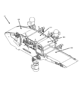
Figure 1 shows an isometric view of the roller system
for laminated products of present invention.
Figure 2 shows a longitudinal cut of the roller system
for laminated products of present invention.
Figure 3 shows detail of the guiding rails for the start
roller belt and for the roller belt of the roller system for
laminated products of present invention.
3
Date Recue/Date Received 2022-05-04

Figure 4 shows the transference of laminated products
from the conveyor belt towards the start roller belt.
Figure 5 shows the rolling of the laminated products
undertaken from the start roller belt and the roller belt.
Figure 6 displays the unloading of the rolled products
from the roller belt towards the unloading belt.
DETAILED DESCRIPTIO OF THE INVENTION
The following description is made referencing figures 1
through 6 indistinctively.
The present invention refers to a roller system (10) for
laminated products (1) based on any type of mass and/or
combination thereof. Said roller system (10) is found set
over a main support structure (20).
The roller system (10) presents a feeding belt (100),
which itself presents an entrance end (101) and an exit end
(102), said feeding belt (100) is found partially mounted
unto a first mobile support structure (110), the feeding belt
(100) presents a tilting movement at the exit end (102), in
such a way that the first support structure presents a pivot
4
Date Recue/Date Received 2022-05-04

(111) near the entrance end (101) of the feeding belt (100),
in such a way that the first support structure (110) moves in
accordance to the main support structure (20), said feeding
belt (100) presents a plurality of tracking rollers (103),
one tension roller (104) and one driver roller (105), the
tensing roller (104) and the driver roller (105) are found
set on the first support structure (110), while the tracking
rollers (103) are distributed between the first support
structure (110) and the main support structure (20); said
tension roller (104) is displaced vertically within a groove
(113)
set unto a lateral wall (112) of the first support
structure (110).
The exit end (102) of the feeding belt (100) is found in
communication with an entrance end (201) of a conveyor belt
(200) preferably mounted on a horizontal plane on the upper
end of the main support structure (20), said conveyor belt
(200) presents an exit end (202) opposite to the entrance end
(201), a plurality of tracking rollers (203), a tension roller
(204) and one driver roller (205), the tension roller (204)
is displaced angularly to be able to tense the conveyor belt
(200) and ensure its proper functioning in this way, said
5
Date Recue/Date Received 2022-05-04

displacement is carried out preferably by means of a first
servomotor.
The exit end (202) of the conveyor belt (200) is found
in communication with the working surface (303) of a start
roller belt (300) set on a vertical plane, in such a way that
it is found perpendicular to the conveyor belt (200), said
start roller belt (300) comprises a driver roller (301) and
at least two tracking rollers (302); said start roller belt
(300) has the ability to displace itself at a velocity and/or
in a direction different from those of the conveyor belt
(200), the above in order to achieve different types of
rolling on the laminated products (1), said start roller belt
(300) is found mounted on a second mobile support structure
(330), said second mobile support structure (330) is found
supported on a longitudinal guide rail (340) set over the
main support structure (20) to longitudinally move the start
roller belt (300) in relation to the conveyor belt (200), in
such a way that said start roller belt is able to
approach/distance itself from the conveyor belt (200), this
adjustment allows achieving the desired aperture on the
rolling product (2), this adjustment is crucial to achieve
6
Date Recue/Date Received 2022-05-04

the rolling of the product, and it is undertaken, preferably
by means of a second servomotor.
A rolling belt (400) set on an inclined plane which
presents an entrance end (401) and an exit end (402), the
roller belt (400) comprises a plurality of tracking rollers
(403), a tension - driver roller (404); the entrance end (401)
is found at a higher point in relation to the exit end (402),
similarly, said entrance end (401) is found below the exit
end (102) of the conveyor belt (200) and in close proximity
to the working surface (301) of the start roller belt (300);
said roller belt (400) is found mounted over a third mobile
support structure (430) which is found mounted over a vertical
guide rail (431), said vertical rail guide (431) is found
mounted over the second mobile support structure (330), in
such a way that said roller belt (400) moves vertically in
relation to the start roller belt (300), this adjustment
allows approaching or distancing the roller belt to the return
of the discharging belt (500). This adjustment allows
ensuring and maintaining the desired aperture on the rolling
product (2) and is carried out preferably by means of a third
servomotor.
7
Date Recue/Date Received 2022-05-04

Given that the third and second mobile support
structures (430, 330) are found connected, upon
approaching/distancing the start roller belt (300) of the
conveyor belt (200), consequently the roller belt (400) also
approaches/distances itself longitudinally from/to second
mobile support structure (330) of said conveyor belt (200),
so that said roller belt (400) has two movements, a vertical
movement and a longitudinal movement.
An unloading belt (500) which receives the laminated
product (1) once it has been rolled from the rolling belt
(400), which additionally feeds the rolled product (2) to the
next step of the process, whether it is to be baked or fried.
Said belt comprises an entrance end (501), an exit end (502),
a plurality of tracking rollers (503) and a tensing-driving
roller (505), said unloading belt is found mounted on the
main support structure (20).
Alterations to the structure described in the present
would be able to be foreseen by those persons skilled in the
art. However, it must be understood that the present
description is related with the preferred embodiments of the
invention, which is merely for illustrative purposes only,
and must not be understood as a limitation of the invention.
8
Date Recue/Date Received 2022-05-04

All obvious embodiments within the spirit of the invention,
such as changes to the shape, material and sizes of the
elements which make up the invention, must be considered as
lying within the scope of the attached claims.
10
9
Date Recue/Date Received 2022-05-04

Representative Drawing
A single figure which represents the drawing illustrating the invention.
Administrative Status

For a clearer understanding of the status of the application/patent presented on this page, the site Disclaimer , as well as the definitions for Patent , Administrative Status , Maintenance Fee  and Payment History  should be consulted.

Administrative Status

Title Date
Forecasted Issue Date 2023-03-21
(86) PCT Filing Date 2015-11-04
(87) PCT Publication Date 2016-06-23
(85) National Entry 2017-06-19
Examination Requested 2020-11-04
(45) Issued 2023-03-21

Abandonment History

There is no abandonment history.

Maintenance Fee

Last Payment of $210.51 was received on 2023-10-27


 Upcoming maintenance fee amounts

Description Date Amount
Next Payment if standard fee 2024-11-04 $277.00
Next Payment if small entity fee 2024-11-04 $100.00

Note : If the full payment has not been received on or before the date indicated, a further fee may be required which may be one of the following

  • the reinstatement fee;
  • the late payment fee; or
  • additional fee to reverse deemed expiry.

Patent fees are adjusted on the 1st of January every year. The amounts above are the current amounts if received by December 31 of the current year.
Please refer to the CIPO Patent Fees web page to see all current fee amounts.

Payment History

Fee Type Anniversary Year Due Date Amount Paid Paid Date
Registration of a document - section 124 $100.00 2017-06-19
Application Fee $400.00 2017-06-19
Maintenance Fee - Application - New Act 2 2017-11-06 $100.00 2017-06-19
Maintenance Fee - Application - New Act 3 2018-11-05 $100.00 2018-10-19
Maintenance Fee - Application - New Act 4 2019-11-04 $100.00 2019-10-18
Maintenance Fee - Application - New Act 5 2020-11-04 $200.00 2020-10-30
Request for Examination 2020-11-04 $800.00 2020-11-04
Maintenance Fee - Application - New Act 6 2021-11-04 $204.00 2021-10-29
Maintenance Fee - Application - New Act 7 2022-11-04 $203.59 2022-10-28
Final Fee $306.00 2023-01-11
Maintenance Fee - Patent - New Act 8 2023-11-06 $210.51 2023-10-27
Owners on Record

Note: Records showing the ownership history in alphabetical order.

Current Owners on Record
HEAT AND CONTROL INC.
Past Owners on Record
None
Past Owners that do not appear in the "Owners on Record" listing will appear in other documentation within the application.
Documents

To view selected files, please enter reCAPTCHA code :


To view images, click a link in the Document Description column. To download the documents, select one or more checkboxes in the first column and then click the "Download Selected in PDF format (Zip Archive)" or the "Download Selected as Single PDF" button.

List of published and non-published patent-specific documents on the CPD .

If you have any difficulty accessing content, you can call the Client Service Centre at 1-866-997-1936 or send them an e-mail at CIPO Client Service Centre.


Document
Description 
Date
(yyyy-mm-dd) 
Number of pages   Size of Image (KB) 
Amendment / Request for Examination 2020-11-04 7 263
Change to the Method of Correspondence 2020-11-04 3 67
Description 2017-12-08 6 236
Claims 2020-11-04 2 106
Examiner Requisition 2022-01-20 3 153
Amendment 2022-05-04 17 483
Description 2022-05-04 9 230
Claims 2022-05-04 2 106
Final Fee 2023-01-11 5 145
Representative Drawing 2023-03-01 1 20
Cover Page 2023-03-01 1 58
Electronic Grant Certificate 2023-03-21 1 2,527
Abstract 2017-06-19 2 85
Claims 2017-06-19 3 127
Drawings 2017-06-19 6 166
Description 2017-06-19 5 201
Representative Drawing 2017-06-19 1 24
International Search Report 2017-06-19 6 296
Declaration 2017-06-19 1 37
National Entry Request 2017-06-19 12 341
Cover Page 2017-08-31 1 65
Amendment 2017-12-08 5 120