Note: Descriptions are shown in the official language in which they were submitted.
CA 02971603 2017-06-19
WO 2016/106016
PCT/US2015/065742
POROUS ADHESIVE NETWORKS IN ELECTROCHEMICAL DEVICES
Cross Reference to Related Application
This application claims the benefit of U.S. Provisional Patent Application No.
62/096638, filed
December 24, 2014, the disclosure of which is incorporated by reference herein
in its entirety.
Background
[0001] In certain electrochemical devices, such as polymer electrolyte
membrane fuel cells, an
electrocatalyst material such as supported or unsupported platinum
nanoparticles is coated on or attached
to at least one side of the polymer electrolyte membrane. Electrical current
may be conducted to and
from the electrocatalyst material by means of an adjacent, electrically
conductive and porous gas
distribution layer, which is often a carbon paper, carbon felt, or carbon
cloth material. The conductive
gas distribution layer should maintain good physical and electrical contact
with the electrochemically
active area of the catalyst coated membrane. This is often accomplished in
part by compressing the
various cell components together when assembling the cell. In addition, the
gas distribution layers and
catalyst coated membrane can be adhesively bonded together outside of the
catalyst active area.
However, as a result of differences in the thermal expansion coefficients of
the gas distribution layer and
the catalyst coated membrane, as well as variations in the degree of swelling
of the hydrophilic catalyst
coated membrane with variations in cell temperature and degree of hydration,
the catalyst coated
membrane and gas distribution layer can separate or "pillow." It would be
desirable to provide
additional "anchoring" of the gas distribution layers to the catalyst coated
membrane in the active area,
to maintain electrical contact and to allow the combination to be handled as a
single unit during cell
assembly. However, such anchoring attachment points should not significantly
block portions of the
active area, or otherwise diminish the performance of the electrochemical cell
(see, e.g., U.S. Pat. No.
7,147,959, Kohler et al.).
Summary
[0002] In one aspect, the present disclosure describes an article comprising a
first gas distribution layer,
a first gas dispersion layer, or a first electrode layer having first and
second opposed major surfaces and
a first adhesive layer having first and second opposed major surfaces, wherein
the second major surface
of the first gas distribution layer, the first major surface of the first
adhesive layer contacts at least the
central area of the second major surface of the first gas dispersion layer, or
the second major surface of
the first adhesive layer contacts at least the central area of the first major
surface of the first electrode
layer, as applicable, has a central area, wherein the first major surface of
the first adhesive layer contacts
-1-
CA 02971603 2017-06-19
WO 2016/106016
PCT/US2015/065742
at least the central area of the second major surface of the first gas
distribution layer, the second major
surface of the first gas dispersion layer, or the first major surface of the
first electrode layer, as
applicable, and wherein the first adhesive layer comprises a porous network of
first adhesive including a
continuous pore network extending between the first and second major surfaces
of the first adhesive
layer. In some embodiments, there is one or more additional adhesive layers
with the first major surface
of the applicable adhesive layer contacting at least the central area of the
second major surface of the
first gas distribution layer, the second major surface of the first gas
dispersion layer, or the first major
surface of the first electrode layer, as applicable.
[0003] Articles described herein are useful, for example, in membrane
electrode assemblies, unitized
electrode assemblies, and electrochemical devices (e.g., fuel cells, redox
flow batteries, and
electrolyzers). Membrane electrode assemblies are used to make electrochemical
devices such as fuel
cells and electrolyzers. Unitized electrode assemblies are used to make
electrochemical devices such
redox flow batteries.
Brief Description of the Drawings
[0004] FIG. 1 is an exploded schematic of an exemplary article described
herein.
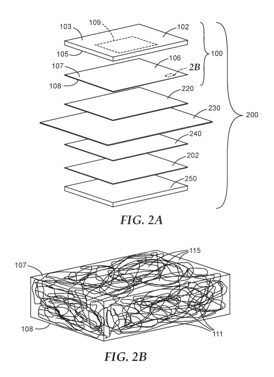
[0005] FIG. 2A is an exploded schematic of an exemplary embodiment of a fuel
cell having a
membrane electrode assembly described herein that includes the article shown
in FIG. 1.
[0006] FIG. 2B is a perspective view of a portion of the first adhesive layer
shown in FIGS. 1 and 2A.
[0007] FIG. 3A is a schematic of exemplary embodiments of membrane electrode
assemblies described
herein.
[0008] FIG. 3B is a schematic of an exemplary embodiment of a fuel cell having
an exemplary
membrane electrode assembly described herein.
[0009] FIG. 4 is a schematic of an exemplary embodiment of an electrolyzer
having a membrane
electrode assembly described herein.
[0010] FIG. 5A is a scanning electron microscope (SEM) surface image at 500x
of a porous adhesive
layer in Example 5.
[0011] FIG. 5B is a scanning electron microscope (SEM) surface image at 1700x
of a porous adhesive
layer in Example 5.
[0012] FIG. 6 is a schematic view of a device for electrospinning nanofibers
onto a substrate.
[0013] FIG. 7 is a chart showing 180 degree peel strengths measured according
to ASTM D3330 for
nanofiber-adhesive-coated gas diffusion layers prepared as in Examples 1-3
that have been bonded to a
catalyst coated membranes.
-2-
CA 02971603 2017-06-19
WO 2016/106016
PCT/US2015/065742
[0014] FIG. 8 is a plot showing a galvano-dynamic scanning (GDS) polarization
performance
comparison between membrane electrode assemblies having electrospun gas
diffusion layer adhesive
(with and without high temperature bonding) and an unbonded control sample.
[0015] FIG. 9 is a plot comparing the high frequency resistance of membrane
electrode assemblies
containing an electrospun gas diffusion layer adhesive (with and without high
temperature bonding) to
an unbonded control sample.
[0016] FIG. 10 is a plot comparing the sensitivity to reduction in cathode air
stoichiometry of
membrane electrode assemblies containing electrospun gas diffusion layer
adhesive (with and without
bonding) to the sensitivity of an unbonded control sample.
Detailed Description
[0017] Referring to FIGS. 1 and 2B, article 100 has first gas distribution
layer 102 with first and second
opposed major surfaces 103, 105 and first adhesive layer 106 with first and
second opposed major
surfaces 107, 108. Second major surface 105 of first gas distribution layer
102 has central area 109.
First major surface 107 of first adhesive layer 106 contacts at least central
area 109 of second major
surface 105 of first gas distribution layer 102. First adhesive layer 106
comprises porous network 111 of
adhesive including continuous pore network 115 extending between first and
second major surfaces 107,
108 of first adhesive layer 106. In addition, or alternatively, an adhesive
layer like adhesive layer 106
could contact a central area of a gas dispersion layer and/or an electrode
(e.g., anode catalyst or cathode
catalyst) layer.
[0018] In some embodiments, the article having a first adhesive layer
contacting at least a central area
of the second major surface of a gas distribution layer further comprises a
first catalyst layer having first
and second opposed major surfaces, wherein the second major surface of the
first adhesive layer contacts
the first major surface of the first catalyst layer. In some embodiments, the
article having a first adhesive
layer contacting at least a central area of the second major surface of a gas
distribution layer further
comprises a first gas dispersion layer having first and second opposed major
surfaces, and a first catalyst
layer having first and second opposed major surfaces, wherein the second major
surface of the first
adhesive layer contacts the first major surface of the first gas dispersion
layer, and wherein the layers in
order are the first gas distribution layer, the first adhesive layer, the
first gas dispersion layer, and the
first catalyst layer.
[0019] Exemplary adhesives comprise fluorinated thermoplastics (e.g.,
polyvinylidene fluoride (PVDF)
or poly(tetrafluoroethylene-co-vinylidene fluoride-co-hexafluoropropylene,)
(available, for example,
under the trade designation "THY 220" from 3M Company, St. Paul, MN) and
hydrocarbon
thermoplastics (e.g., acrylate and rubber, styrene)).
-3-
CA 02971603 2017-06-19
WO 2016/106016
PCT/US2015/065742
[0020] In some embodiments, the porous network of the first adhesive comprises
a plurality of first
elongated adhesive elements (e.g., fibers). In some embodiments, the first
elongated adhesive elements
have an aspect ratio of at least 10:1 (in some embodiments, an aspect ratio of
at least 100:1 to 1000:1, or
even at least 10000:1). In some embodiments, the first elongated adhesive
elements have lengths of at
least 10 micrometers (in some embodiments, at least 25 micrometers, 100
micrometers, or even at least 1
centimeter) and at least one of diameters or widths in a range from 50 nm to
10000 nm (in some
embodiments, in the range from 100 nm to 2000 nm, 200 nm to 1000 nm, or even
300 nm to 500 nm).
[0021] In some embodiments, an adhesive layer has porosity of at least 50
percent (in some
embodiments, at least 55, 60, 65, 70, 75, 80, 90 percent or even at least 95
percent; in some
embodiments, in the range from 50 to 90, 60 to 80, or even 60 to 75), based on
the total volume of the
adhesive layer (i.e., the total pore volume and solid volume of the adhesive
layer). In some
embodiments, the adhesive layer has a thickness up to 10 micrometers (in some
embodiments, up to 9
micrometers, 8 micrometers, 7 micrometers, 6 micrometers, 5 micrometers, 4
micrometers, 3
micrometers, 2 micrometers, or even up to 1 micrometer; in some embodiments,
in a range from 0.5
micrometer to 10 micrometers, 0.5 micrometer to 5 micrometers, or even 0.5
micrometer to 2
micrometers).
[0022] The adhesive layer can be provided, for example, by:
providing a first gas distribution layer, a first gas dispersion layer, or a
first electrode
layer, as applicable, having first and second opposed major surfaces, wherein
the first and
second major surfaces of the first gas distribution layer, the first gas
dispersion layer, or the first
electrode layer, as applicable, each have an active area;
providing an adhesive composition; and
at least one of electrospinning or electrospraying the adhesive composition
onto at least
the active area of the second major surface of the first gas distribution
layer, of the second major
surface of the first gas dispersion layer, or of the first major surface of
the first electrode layer, as
applicable, to provide the adhesive layer.
[0023] Processes producing polymer nanofibers via electrostatic spinning or
"electrospinning" are
known in the art, and include those described, for example, in
"Electrospinning of Nanofibers:
Reinventing the Wheel?", D. Li and Y. Xia, Advanced Materials, Volume 16,
Issue 14, pages 1151-
1170, July 2004. An exemplary electrospinning apparatus 600 is shown in FIG.
6. The process in
general involves forcing a polymer solution or melt through a small-bore metal
tube (such as syringe
needle 620 of syringe 630) that is held at a high electrical potential via a
high voltage generator, 640. As
the polymer solution is extruded and the solvent evaporates or the polymer
melt cools, there is formed a
polymer filament 650 that is collected on a grounded target substrate or
collector 660. The collected
electrospun nanofiber filaments 650 form a porous nonwoven fabric 670 on the
target substrate 660.
-4-
CA 02971603 2017-06-19
WO 2016/106016
PCT/US2015/065742
[0024] An exemplary article (e.g., a membrane electrode assembly or a unitized
electrode assembly)
comprises, in order:
a first gas distribution layer having first and second opposed major surfaces;
optionally a first gas dispersion layer having first and second opposed major
surfaces;
an anode catalyst layer having first and second opposed major surface, the
anode
catalyst comprising first catalyst;
a membrane;
a cathode catalyst layer having first and second opposed major surfaces, the
cathode
catalyst comprising a second catalyst;
optionally a second gas dispersion layer having first and second opposed major
surfaces; and
a second gas distribution layer having first and second opposed major
surfaces,
wherein at least one of (i.e., any one or any combinations):
further comprising an (e.g., first, second, third, etc., as applicable)
adhesive layer having first
and second opposed major surfaces, wherein the adhesive layer comprises a
porous network of adhesive
including a continuous pore network extending between the first and second
major surfaces of the
adhesive layer, wherein the second major surface of the first gas distribution
layer has a central area,
wherein the first major surface of the adhesive layer contacts at least the
central area of the second major
surface of the first gas distribution layer;
further comprising an (e.g., first, second, third, etc., as applicable)
adhesive layer having first
and second opposed major surfaces, wherein the adhesive layer comprises a
porous network of adhesive
including a continuous pore network extending between the first and second
major surfaces of the
adhesive layer, wherein the second major surface of the first gas dispersion
layer has a central area,
wherein the first major surface of the adhesive layer contacts at least the
central area of the second major
surface of the first gas distribution layer;
further comprising an (e.g., first, second, third, etc., as applicable)
adhesive layer having first
and second opposed major surfaces, wherein the adhesive layer comprises a
porous network of adhesive
including a continuous pore network extending between the first and second
major surfaces of the
adhesive layer, wherein the first major surface of the anode catalyst layer
has a central area, wherein the
second major surface of the adhesive layer contacts at least the central area
of the first major surface of
the anode catalyst layer;
further comprising an (e.g., first, second, third, etc., as applicable)
adhesive layer having first
and second opposed major surfaces, wherein the adhesive layer comprises a
porous network of adhesive
including a continuous pore network extending between the first and second
major surfaces of the
adhesive layer, wherein the second major surface of the cathode catalyst layer
has a central area, wherein
the first major surface of the adhesive layer contacts at least the central
area of the second major surface
of the cathode catalyst layer;
-5-
CA 02971603 2017-06-19
WO 2016/106016
PCT/US2015/065742
further comprising an (e.g., first, second, third, etc., as applicable)
adhesive layer having first
and second opposed major surfaces, wherein the adhesive layer comprises a
porous network of adhesive
including a continuous pore network extending between the first and second
major surfaces of the
adhesive layer, wherein the first major surface of the second gas dispersion
layer has a central area,
wherein the second major surface of the adhesive layer contacts at least the
central area of the first major
surface of the second gas dispersion layer; or
further comprising an (e.g., first, second, third, etc., as applicable)
adhesive layer having first
and second opposed major surfaces, wherein the adhesive layer comprises a
porous network of adhesive
including a continuous pore network extending between the first and second
major surfaces of the
adhesive layer, wherein the first major surface of the second gas distribution
layer has a central area,
wherein the second major surface of the adhesive layer contacts at least the
central area of the first major
surface of the second gas distribution layer. For example, referring to FIG.2,
exemplary membrane
electrode assembly 200 has article 100 (see FIG. 1), catalyst layer 220 (e.g.,
an anode catalyst layer),
membrane 230, a second catalyst layer 240 (e.g., a cathode catalyst layer),
optional second adhesive
layer 202, and second gas distribution layer 250.
[0025] A gas distribution layer generally delivers gas evenly to the
electrodes and in some embodiments
conducts electricity. It also provides removal of water in either vapor or
liquid form, in the case of a fuel
cell. An exemplary gas distribution layer is a gas diffusion layer, also
sometimes referred to as a macro-
porous gas diffusion backing (GDB). Sources of gas distribution layers include
carbon fibers randomly
oriented to form porous layers, in the form of non-woven paper or woven
fabrics. The non-woven
carbon papers are available, for example, from Mitsubishi Rayon Co., Ltd.,
Tokyo, Japan, under the
trade designation "GRAFIL U-105;" Toray Corp., Tokyo, Japan, under the trade
designation "TORAY,"
AvCarb Material Solutions, Lowell, MA, under the trade designation "AVCARB,"
SGL Group, the
Carbon Company, Wiesbaden, Germany, under trade designation "SIGRACET,"
Freudenberg FCCT SE
& Co. KG, Fuel Cell Component Technologies, Weinheim, Germany, under trade
designation
"FREUDENBERG," and Engineered Fibers Technology (EFT), Shelton, CT, under
trade designation
"SPECTRACARB GDL." The woven carbon fabrics or cloths are available, for
example, from
ElectroChem Inc., Woburn, MA, under the trade designations "EC-CC1-060" and
"EC-AC-CLOTH,"
NuVant Systems Inc., Crown Point, IN, under the trade designations "ELAT-LT"
and "ELAT," BASF
Fuel Cell GmbH, North America, under the trade designation "E-TEK ELAT LT,"
and Zoltek Corp., St.
Louis, MO, under the trade designation "ZOLTEK CARBON CLOTH."
[0026] In some embodiments, carbon-supported catalyst particles are used.
Typical carbon-supported
catalyst particles are present in a range from 50 to 90 wt.% carbon and
catalyst metal in a range from 50
to 10 wt.%, wherein for fuel cells the catalyst metal typically comprises Pt
for the cathode and Pt or Pt
and Ru in a weight ratio of about 2:1 for the anode. Typically, the catalyst
is applied to the polymer
electrolyte membrane or to the gas diffusion layer in the form of a catalyst
ink. Alternately, for example,
the catalyst ink may be applied to a transfer substrate, dried, and thereafter
applied to the polymer
-6-
CA 02971603 2017-06-19
WO 2016/106016
PCT/US2015/065742
electrolyte membrane or to the gas diffusion layer as a decal. The catalyst
ink typically comprises
polymer electrolyte material, which may or may not be the same polymer
electrolyte material which
comprises the polymer electrolyte membrane. The catalyst ink typically
comprises a dispersion of
catalyst particles in a dispersion of the polymer electrolyte. The ink
typically contains in a range from 5
to 30 wt.% solids (i.e., polymer and catalyst) and more typically in a range
from 10 to 20 wt.% solids.
The electrolyte dispersion is typically an aqueous dispersion, which may
additionally contain alcohols
and polyalcohols (e.g., glycerin and ethylene glycol). The water, alcohol, and
polyalcohol content may
be adjusted to alter rheological properties of the ink. In some embodiments,
the ink typically contains in
a range from 0 to 50 wt.% alcohol and in a range from 0 to 20 wt.%
polyalcohol. In some embodiments,
the ink may contain in a range from 0 to 2 wt.% of a suitable dispersant. The
ink can be made, for
example, by stirring with heat followed by dilution to a coatable consistency.
Ink can be coated, for
example, onto a liner or the membrane itself by both hand and machine methods,
including hand
brushing, notch bar coating, fluid bearing die coating, wire-wound rod
coating, fluid bearing coating,
slot-fed knife coating, three-roll coating, or decal transfer. Coating may be
achieved in one application
or in multiple applications. In some embodiments the cathode and/or anode
catalyst can be secured to
the membrane to form a catalyst coated membrane by pressure or a combination
of pressure and
temperature in a press or nip for roll attachment.
[0027] In some embodiments, the cathode and/or anode catalyst layer comprises
nanostructured
whiskers with the catalyst thereon. Nanostructured whiskers can be provided by
techniques known in
the art, including those described in U.S. Pat. Nos. 4,812,352 (Debe),
5,039,561 (Debe), 5,338,430
(Parsonage et al.), 6,136,412 (Spiewak et al.), and 7,419,741 (Vernstrom et
al.), the disclosures of which
are incorporated herein by reference. In general, nanostructured whiskers can
be provided, for example,
by vacuum depositing (e.g., by sublimation) a layer of organic or inorganic
material onto a substrate
(e.g., a microstructured catalyst transfer polymer sheet), and then, in the
case of perylene red deposition,
converting the perylene red pigment into nanostructured whiskers by thermal
annealing. Typically the
vacuum deposition steps are carried out at total pressures at or below about
le Ton or 0.1 Pascal.
Exemplary microstructures are made by thermal sublimation and vacuum annealing
of the organic
pigment C.I. Pigment Red 149 (i.e., N,N'-di(3,5-xylyl)perylene-3,4:9,10-
bis(dicarboximide)). Methods
for making organic nanostructured layers are disclosed, for example, in
Materials Science and
Engineering, A158 (1992), pp. 1-6; J. Vac. Sci. Technol. A, 5 (4), July/August
1987, pp. 1914-16; J.
Vac. Sci. Technol. A, 6, (3), May/August 1988, pp. 1907-11; Thin Solid Films,
186, 1990, pp. 327-47; J.
Mat. Sci., 25, 1990, pp. 5257-68; Rapidly Quenched Metals, Proc. of the Fifth
Int. Conf. on Rapidly
Quenched Metals, Wurzburg, Germany (Sep. 3-7, 1984), S. Steeb et al., eds.,
Elsevier Science
Publishers B.V., New York, (1985), pp. 1117-24; Photo. Sci. and Eng., 24, (4),
July/August 1980, pp.
211-16; and U.S. Pat. Nos. 4,340,276 (Maffitt et al.) and 4,568,598 (Bilkadi
et al.), the disclosures of
which are incorporated herein by reference. Properties of catalyst layers
using carbon nanotube arrays
are disclosed in the article "High Dispersion and Electrocatalytic Properties
of Platinum on Well-
-7-
CA 02971603 2017-06-19
WO 2016/106016
PCT/US2015/065742
Aligned Carbon Nanotube Arrays", Carbon, 42 (2004), 191-197. Properties of
catalyst layers using
grassy or bristled silicon are disclosed, for example, in U.S. Pat. App. Pub.
No. 2004/0048466 Al (Gore
et al.).
[0028] Vacuum deposition may be carried out in any suitable apparatus (see,
e.g., U.S. Pat. Nos.
5,338,430 (Parsonage et al.), 5,879,827 (Debe et al.), 5,879,828 (Debe et
al.), 6,040,077 (Debe et al.),
and 6,319,293 (Debe et al.), and U.S. Pat. App. Pub. No. 2002/0004453 Al
(Haugen et al.), the
disclosures of which are incorporated herein by reference.) One exemplary
apparatus is depicted
schematically in FIG. 4A of U.S. Pat. No. 5,338,430 (Parsonage et al.), and
discussed in the
accompanying text, wherein the substrate is mounted on a drum which is then
rotated over a sublimation
or evaporation source for depositing the organic precursor (e.g., perylene red
pigment) prior to annealing
the organic precursor in order to form the nanostructured whiskers.
[0029] Typically, the nominal thickness of deposited perylene red pigment is
in a range from about 50
nm to 500 nm. Typically, the whiskers have an average cross-sectional
dimension in a range from 20
nm to 60 nm and an average length in a range from 0.3 micrometer to 3
micrometers.
[0030] In some embodiments, the whiskers are attached to a backing. Exemplary
backings comprise
polyimide, nylon, metal foils, or other material that can withstand the
thermal annealing temperature up
to 300 C. In some embodiments, the backing has an average thickness in a range
from 25 micrometers
to 125 micrometers.
[0031] In some embodiments, the backing has a microstructure on at least one
of its surfaces. In some
embodiments, the microstructure is comprised of substantially uniformly shaped
and sized features at
least three (in some embodiments, at least four, five, ten, or more) times the
average size of the
nanostructured whiskers. The shapes of the microstructures can, for example,
be V-shaped grooves and
peaks (see, e.g., U.S. Pat. No. 6,136,412 (Spiewak et al.), the disclosure of
which is incorporated herein
by reference) or pyramids (see, e.g., U.S. Pat. No. 7,901,829 (Debe et al.),
the disclosure of which is
incorporated herein by reference). In some embodiments some fraction of the
microstructure features
extend above the average or majority of the microstructured peaks in a
periodic fashion, such as every
31' V-groove peak being 25% or 50% or even 100% taller than those on either
side of it. In some
embodiments, this fraction of features that extend above the majority of the
microstructured peaks can be
up to 10% (in some embodiments up to 3%, 2%, or even up to 1%). Use of the
occasional taller
microstructure features may facilitate protecting the uniformly smaller
microstructure peaks when the
coated substrate moves over the surfaces of rollers in a roll-to-roll coating
operation. The occasional
taller feature touches the surface of the roller rather than the peaks of the
smaller microstructures, so
much less of the nanostructured material or whisker material is likely to be
scraped or otherwise
disturbed as the substrate moves through the coating process. In some
embodiments, the microstructure
features are substantially smaller than half the thickness of the membrane
that the catalyst will be
transferred to in making a membrane electrode assembly. This is so that during
the catalyst transfer
-8-
CA 02971603 2017-06-19
WO 2016/106016
PCT/US2015/065742
process, the taller microstructure features do not penetrate through the
membrane where they may
overlap the electrode on the opposite side of the membrane. In some
embodiments, the tallest
microstructure features are less than 1/31d or 114th of the membrane
thickness. For the thinnest ion
exchange membranes (e.g., about 10 micrometers to 15 micrometers in
thickness), it may be desirable to
have a substrate with microstructured features no larger than about 3
micrometers to 4.5 micrometers
tall. The steepness of the sides of the V-shaped or other microstructured
features or the included angles
between adjacent features may in some embodiments be desirable to be on the
order of 90 for ease in
catalyst transfer during a lamination-transfer process and to have a gain in
surface area of the electrode
that comes from the square root of two (1.414) surface area of the
microstructured layer relative to the
planar geometric surface of the substrate backing.
[0032] Exemplary catalysts contained in the anode catalyst layer include at
least one of:
(a) at least one of elemental Au, Co, Fe, Ir, Mn, Ni, Os, Pd, Pt, Rh, or Ru;
(b) at least one alloy comprising at least one of Au, Co, Fe, Ir, Mn, Ni, Os,
Pd, Pt, Rh, or Ru;
(c) at least one composite comprising at least one of Au, Co, Fe, Ir, Mn, Ni,
Os, Pd, Pt, Rh, or
Ru;
(d) at least one oxide, hydrated oxide or hydroxide of at least one of Au, Co,
Fe, Ir, Mn, Ni, Os,
Pd, Pt, Rh, or Ru;
(e) at least one organometallic complex of at least one of Au, Co, Fe, Ir, Mn,
Ni, Os, Pd, Pt, Rh,
or Ru;
(f) at least one carbide of at least one of Au, Co, Fe, Ir, Mn, Ni, Os, Pd,
Pt, Rh, or Ru;
(g) at least one fluoride of at least one of Au, Co, Fe, Ir, Mn, Ni, Os, Pd,
Pt, Rh, or Ru;
(h) at least one nitride of at least one of Au, Co, Fe, Ir, Mn, Ni, Os, Pd,
Pt, Rh, or Ru;
(i) at least one boride of at least one of Au, Co, Fe, Ir, Mn, Ni, Os, Pd, Pt,
Rh, or Ru;
(j) at least one oxycarbide of at least one of Au, Co, Fe, Ir, Mn, Ni, Os, Pd,
Pt, Rh, or Ru;
(k) at least one oxyfluoride of at least one of Au, Co, Fe, Ir, Mn, Ni, Os,
Pd, Pt, Rh, or Ru;
(1) at least one oxynitride of at least one of Au, Co, Fe, Ir, Mn, Ni, Os, Pd,
Pt, Rh, or Ru; or
(m) at least one oxyboride of at least one of Au, Co, Fe, Ir, Mn, Ni, Os, Pd,
Pt, Rh, or Ru,
(where it is understood that the oxides, organometallic complexes, borides,
carbides, fluorides, nitrides,
oxyborides, oxycarbides, oxyfluorides, and oxynitrides are those that exist
with Au, Co, Fe, Ir, Mn, Ni,
Os, Pd, Pt, Rh, or Ru).
[0033] Exemplary oxides include CoO, Co203, Co304, CoFe204, FeO, Fe203, Fe304,
Fe405, NiO, Ni203,
NixFey0z, NiõCoyOz, MnO, Mn203, Mn304, Irx0y where Jr valence could be, for
example, 2-8. Specific
exemplary Jr oxides include Ir203, Ir02, Ir03, and Ir04, as well as mixed
IrxRuyOz, IrõPty0z, IrxRhyOz,
IrxRuyPtz0zz, IrxRhyPtz0z., IrxPdyPtz0zz, IrõPdy0z, IrxRuyPdzOzzõIrxRhyPdzOzz,
or iridate Ir-Ru pyrochlore
oxide (e.g., NaxCeyIrzRuzz07); Ru oxides include Rux100, where valence could
be, for example, 2-8.
Specific exemplary Ru oxides include Ru203, Ru02, and Ru03, or ruthenate Ru-Ir
pyrochlore oxide (e.g.,
-9-
CA 02971603 2017-06-19
WO 2016/106016
PCT/US2015/065742
NaxCeyRuzIrzz07). Exemplary Pd oxides include Pdx0y forms where Pd valence
could be, for example,
1, 2, and 4. Specific exemplary Pd oxides include Pd0, Pd02. Other oxides
include Os, Rh, or Au
oxides 0s02, 0s04, RhO, Rh02, Rh203,Oy and Au203, Au20, and AuxOy. Exemplary
organometallic complexes include at least one of Au, Co, Fe, Ni, Ir, Pd, Rh,
Os, or Ru, where Au, Co,
Fe, Ir, Ni, Pd, Pt, Rh, or Ru form coordination bonds with organic ligands
through hetero-atom(s) or
non-carbon atom(s) (e.g., oxygen, nitrogen, chalcogens (e.g., sulfur and
selenium), phosphorus, or
halide). Exemplary Au, Co, Fe, Ir, Ni, Pd, Pt, Rh, Os, or Ru complexes with
organic ligands can also be
formed via 7C bonds. Organic ligands with oxygen hetero-atoms include
functional groups such as
hydroxyl, ether, carbonyl, ester, carboxyl, aldehydes, anhydrides, cyclic
anhydrides, and epoxy. Organic
ligands with nitrogen hetero atoms include functional groups such as amine,
amide, imide, imine, azide,
azine, pyrrole, pyridine, porphyrine, isocyanate, carbamate, carbamide
sulfamate, sulfamide, amino
acids, and N-heterocyclic carbine. Organic ligands with sulfur hetero atoms,
so-called thio-ligands,
include functional groups such as thiol, thioketone (thione or thiocarbonyl),
thial, thiophene, disulfides,
polysulfides, sulfimide, sulfoximide, and sulfonediimine. Organic ligands with
phosphorus hetero-atoms
include functional groups such as phosphine, phosphane, phosphanido, and
phosphinidene. Exemplary
organometallic complexes also include homo and hetero bimetallic complexes
where Au, Co, Fe, Ir, Ni,
Pd, Pt, Rh, Os, or Ru are involved in coordination bonds with either homo or
hetero functional organic
ligands. Au, Co, Fe, Ir, Ni, Pd, Pt, Rh, Os, or Ru organometallic complexes
formed via 7C coordination
bonds include carbon rich 7c¨conjugated organic ligands (e.g., arenes, allyls,
dienes, carbenes, and
alkynyls). Examples of Au, Co, Fe, Ir, Ni, Pd, Pt, Rh, Os or Ru organometallic
complexes are also
known as chelates, tweezer molecules, cages, molecular boxes, fluxional
molecules, macrocycles, prism,
half-sandwich, and metal-organic framework (MOF). Exemplary organometallic
compounds comprising
at least one of Au, Co, Fe, Ir, Ni, Pd, Pt, Rh, Os, or Ru include compounds
where Au, Co, Fe, Ir, Ni, Pd,
Pt, Rh, Os, or Ru bond to organics via covalent, ionic or mixed covalent-ionic
metal-carbon bonds.
Exemplary organometallic compounds can also include a combination of at least
two of Au, Co, Fe, Ir,
Ni, Pd, Pt, Rh, Os, or Ru covalent bonds to carbon atoms and coordination
bonds to organic ligands via
hetero-atoms (e.g., oxygen, nitrogen, chalcogens (e.g., sulfur and selenium),
phosphorus, or halide).
Formulae of stable metallo-organic complexes can typically be predicted from
the 18-electron rule. The
rule is based on the fact that the valence shells of transition metals consist
of nine valence orbitals, which
collectively can accommodate 18 electrons as either bonding or nonbonding
electron pairs. The
combination of these nine atomic orbitals with ligand orbitals creates nine
molecular orbitals that are
either metal-ligand bonding or non-bonding. The rule is not generally
applicable for complexes of non-
transition metals. The rule usefully predicts the formulae for low-spin
complexes of the Cr, Mn, Fe, and
Co triads. Well-known examples include ferrocene, iron pentacarbonyl, chromium
carbonyl, and nickel
carbonyl. Ligands in a complex determine the applicability of the 18-electron
rule. In general,
complexes that obey the rule are composed at least partly of "n-acceptor
ligands" (also known as n-
acids). This kind of ligand exerts a very strong ligand field, which lowers
the energies of the resultant
-10-
CA 02971603 2017-06-19
WO 2016/106016
PCT/US2015/065742
molecular orbitals and thus are favorably occupied. Typical ligands include
olefins, phosphines, and
CO. Complexes of n-acids typically feature metal in a low-oxidation state. The
relationship between
oxidation state and the nature of the ligands is rationalized within the
framework of 7( backbonding.
Exemplary carbides include Au2C2, Ni2C, Ni3C, NiC, Fe2C, Fe3C, FexCy, CoC,
Co2C, Co3C, IrC, IrC2,
IrC4, Inks, IrxCy, RuC, Ru2C, RhC, PtC, OsC, OsC3, OsC2, (MnFe)3C, and Mn3C.
Exemplary fluorides
include AuF, AuF3, AuF5, FeF2, FeF3, CoFe2, CoF3, NiF2, IrF3, IrF4, IrxFy,
PdF3, PdF4, RhF3, RhF4,
RhF6, RuF3, and OsF6. Exemplary nitrides include Au3N, AuN2, AuxNy, Ni3N, NiN,
Co2N, CoN, Co2N3,
Co4N, Fe2N, Fe3Nõ with x = 0.75-1.4, Fe4N, Fe8N, Fe16N2, IrN, IrN2, IrN3, RhN,
RhN2, RhN3, Ru2N,
RuN, RuN2, PdN, PdN2, OsN, OsN2, OsN4, Mn2N, Mn4N, and Mn3N. Exemplary borides
include AuxBy,
Mn2AuB, NiB, Ni3B, Ni4B3, CoB, Co2B, Co3B, FeB, Fe2B, Ru2B3, RuB2, IrB, IrõBy,
OsB, 0s2B3, OsB2,
RhB, ZrRh3B, NbRh3B and YRh3B. Exemplary oxycarbides AuxOyCz, NixOyCz,
FexOyCz, CoxOyCz,
Irx0yCz, RuxOyCz, Rhx0yCz, Ptx0yCz, Pdx0yCz, and Osx0yCz. Exemplary
oxyfluorides include AuxOyFz,
NixOyFz, FexOyFz, CoxOyFz, Irx0yFz, RuxOyFz, Rhx0yFz, Ptx0yFz, Pdx0yFz, and
Osx0yFz. Exemplary
oxynitrides include AuxOyNz, NixOyNz, FexOyNz, CoxOyNz, Irx0yNz, RuxOyNz,
Rhx0yNz, Ptx0yNz,
Pdx0yNz, and Osx0yNz. Exemplary oxyborides include Aux0yBz, NixOyBz, FexOyBz,
Cox0yBz, Irx0yBz,
Rux0yBz, Rhx0yBz, Ptx0yBz, Pdx0yBz, and Osx0yBz. It is within the scope of the
present disclosure to
include composites comprising these oxides, organometallic complexes,
carbides, fluorides, nitrides,
oxycarbides, oxyfluorides, oxynitrides oxyborides, boronitrides, and/or
borocarbides.
[0034] Exemplary catalysts contained in a cathode catalyst layer include at
least one of:
(a") at least one of elemental Au, Co, Fe, Ir, Mn, Ni, Os, Pd, Pt, Rh, or Ru;
(b") at least one alloy comprising at least one of Au, Co, Fe, Ir, Mn, Ni, Os,
Pd, Pt, Rh, or Ru;
(c") at least one composite comprising at least one of Au, Co, Fe, Ir, Mn, Ni,
Os, Pd, Pt, Rh, or
Ru;
(d") at least one oxide of at least one of Au, Co, Fe, Ir, Mn, Ni, Os, Pd, Pt,
Rh, or Ru;
(e") at least one organometallic complex of at least one of Au, Co, Fe, Ir,
Mn, Ni, Os, Pd, Pt,
Rh, or Ru;
(f") at least one carbide of at least one of Au, Co, Fe, Ir, Mn, Ni, Os, Pd,
Pt, Rh, or Ru;
(g") at least one fluoride of at least one of Au, Co, Fe, Ir, Mn, Ni, Os, Pd,
Pt, Rh, or Ru;
(h") at least one nitride of at least one of Au, Co, Fe, Ir, Mn, Ni, Os, Pd,
Pt, Rh, or Ru;
(i") at least one boride of at least one of Au, Co, Fe, Ir, Mn, Ni, Os, Pd,
Pt, Rh, or Ru;
(j") at least one oxycarbide of at least one of Au, Co, Fe, Ir, Mn, Ni, Os,
Pd, Pt, Rh, or Ru;
(k") at least one oxyfluoride of at least one of Au, Co, Fe, Ir, Mn, Ni, Os,
Pd, Pt, Rh, or Ru; or
(1") at least one oxynitride of at least one of Au, Co, Fe, Ir, Mn, Ni, Os,
Pd, Pt, Rh, or Ru; or
(m") at least one oxyboride of at least one of Au, Co, Fe, Ir, Mn, Ni, Os, Pd,
Pt, Rh, or Ru
(where it is understood that the oxides, organometallic complexes, borides,
carbides, fluorides, nitrides,
oxyborides, oxycarbides, oxyfluorides, and oxynitrides are those that exist
with Au, Co, Fe, Ir, Mn, Ni,
Os, Pd, Pt, Rh, or Ru).
-11-
CA 02971603 2017-06-19
WO 2016/106016
PCT/US2015/065742
[0035] Exemplary oxides include CoO, Co203, Co304, CoFe204, FeO, Fe203, Fe304,
Fe405, NiO, Ni203,
NixFey0z, NiõCoyOz; MnO, Mn203, Mn304, and IrxOy, where Jr valence could be,
for example, 2-8.
Specific exemplary Jr oxides include Ir203, Ir02, Ir03, and Ir04, as well as
mixed IrxRuy0., IrxPty0.,
IrxRhyOz, IrxRuyPtz0zz, IrõRhyPtz0zz, IrõPdyPtz0zz, IrõPdy0z, IrxRuyPdzOzz,
IrxRhyPdzOzz, or iridate Jr-Ru
pyrochlore oxide (e.g., NaxCeyIrzRuzz07); Ru oxides include RuxiOyi, where
valence could be, for
example, 2-8. Specific exemplary Ru oxides include Ru203, Ru02, and Ru03, or
ruthenate Ru-Jr
pyrochlore oxide (e.g., NaxCeyRuzIrzz07). Exemplary Pd oxides include Pdx0y
forms where Pd valence
could be, for example, 1, 2, and 4. Specific exemplary Pd oxides include Pd0,
Pd02, Os oxides 0s02
and 0s04, RhO, Rh02, Rh203, Au203,Au20, and Aux0y. Exemplary organometallic
complexes include
at least one of Au, Co, Fe, Ni, Jr, Mn, Pd, Pt, Rh, Os, or Ru, where Au, Co,
Fe, Jr, Ni, Pd, Pt, Rh, Os, or
Ru coordination bonds with organic ligands through hetero-atom(s) or non-
carbon atom(s) (e.g., oxygen,
nitrogen, chalcogens (e.g., sulfur and selenium), phosphorus, or halide).
Exemplary Au, Co, Fe, Jr, Ni,
Pd, Pt, Rh, Os, or Ru complexes with organic ligands can also be formed via TE
bonds. Organic ligands
with oxygen hetero-atoms include functional groups such as hydroxyl, ether,
carbonyl, ester, carboxyl,
aldehydes, anhydrides, cyclic anhydrides, and epoxy. Organic ligands with
nitrogen hetero atoms
include functional groups such as amine, amide, imide, imine, azide, azine,
pyrrole, pyridine, porphyrine,
isocyanate, carbamate, carbamide, sulfamate, sulfamide, amino acids, and N-
heterocyclic carbine.
Organic ligands with sulfur hetero atoms, so-called thio-ligands include
functional groups (e.g., thiol,
thioketone (thione or thiocarbonyl), thial, thiophene, disulfides,
polysulfides, sulfimide, sulfoximide, and
sulfonediimine). Organic ligands with phosphorus hetero-atoms include
functional groups (e.g.,
phosphine, phosphane, phosphanido, and phosphinidene). Exemplary
organometallic complexes also
include homo and hetero bimetallic complexes where Au, Co, Fe, Jr, Ni, Pd, Pt,
Rh, Os, or Ru are
involved in coordination bonds with either homo or hetero functional organic
ligands. Au, Co, Fe, Jr, Ni,
Pd, Pt, Rh, Os, or Ru organometallic complexes formed via TE coordination
bonds include carbon rich 7E-
conjugated organic ligands (e.g., arenes, allyls, dienes, carbenes, and
alkynyls). Examples of Au, Co,
Fe, Jr, Ni, Pd, Pt, Rh, Os, or Ru organometallic complexes are also known as
chelates, tweezer
molecules, cages, molecular boxes, fluxional molecules, macrocycles, prism,
half-sandwich, and metal-
organic framework (MOF). Exemplary organometallic compounds comprising at
least one of Au, Co,
Fe, Jr, Ni, Pd, Pt, Rh, Os, or Ru include compounds where Au, Co, Fe, Jr, Ni,
Pd, Pt, Rh, Os, or Ru bond
to organics via covalent, ionic, or mixed covalent-ionic metal-carbon bonds.
Exemplary organometallic
compounds can also include combinations of at least two of Au, Co, Fe, Jr, Ni,
Pd, Pt, Rh, Os, or Ru
covalent bonds to carbon atoms and coordination bonds to organic ligands via
hetero-atoms (e.g.,
oxygen, nitrogen, chalcogens (e.g., sulfur and selenium), phosphorus, or
halide). Formulae of stable
metallo-organic complexes can typically be predicted from the 18-electron
rule. The rule is based on the
fact that the valence shells of transition metals consist of nine valence
orbitals, which collectively can
accommodate 18 electrons as either bonding or nonbonding electron pairs. The
combination of these
nine atomic orbitals with ligand orbitals creates nine molecular orbitals that
are either metal-ligand
-12-
CA 02971603 2017-06-19
WO 2016/106016
PCT/US2015/065742
bonding or non-bonding. The rule is not generally applicable for complexes of
non-transition metals.
The rule usefully predicts the formulae for low-spin complexes of the Cr, Mn,
Fe, and Co triads. Well-
known examples include ferrocene, iron pentacarbonyl, chromium carbonyl, and
nickel carbonyl.
Ligands in a complex determine the applicability of the 18-electron rule. In
general, complexes that
obey the rule are composed at least partly of n-acceptor ligands (also known
as n-acids). This kind of
ligand exerts a very strong ligand field, which lowers the energies of the
resultant molecular orbitals and
thus are favorably occupied. Typical ligands include olefins, phosphines, and
CO. Complexes of 7E-
acids typically feature metal in a low-oxidation state. The relationship
between oxidation state and the
nature of the ligands is rationalized within the framework of 7( backbonding.
Exemplary carbides
include Au2C2, or other elements carbides (e.g., Ni2C, Ni3C, NiC, Fe2C, Fe3C,
FexCy, CoC, Co2C, Co3C,
IrC, IrC2, IrC4, Ir4C5, IrxCy, Ru2C, RuC, RhC, PtC, OsC, OsC3, and OsC2).
Exemplary fluorides include
AuF, AuF3, AuF5, FeF2, FeF3, CoFe2, CoF3, NiF2, IrF3, IrF4, IrxFy, PdF3, PdF4,
RhF3, RhF4, RhF6, RuF3,
and OsF6. Exemplary nitrides include Au3N, AuN2, AuxNy, Ni3N, NiN, Co2N, CoN,
Co2N3, Co4N, Fe2N,
Fe3Nx with x = 0.75-1.4, Fe4N, Fe8N, Fe16N2, IrN, IrN2, IrN3, RhN, RhN2, RhN3,
Ru2N, RuN, RuN2,
PdN, PdN2, OsN, OsN2, and OsN4. Exemplary borides include AuxBy, Mn2AuB,
NixBy, CoB, Co2B,
Co3B, FeB, Fe2B, Ru2B3, RuB2, IrB, IrxBy, OsB, 0s2B3, OsB2, RhB, and their
oxyborides, boronitrides
and borocarbides. Exemplary oxycarbides include AuxOyCz, NixOyCz, FexOyCz,
CoxOyCz, Irx0yCz,
RuxOyCz, Rhx0yCz, Ptx0yCz, Pdx0yCz, and Osx0yCz. Exemplary oxyfluorides
include AuxOyFz, NixOyFz,
FexOyFz, CoxOyFz, Irx0yFz, RuxOyFz, Rhx0yFz, Ptx0yFz, Pdx0yFz, and Osx0yFz.
Exemplary oxynitrides
include AuxOyNz, NixOyNz, FexOyNz, CoxOyNz, Irx0yNz, RuxOyNz, Rhx0yNz,
Ptx0yNz, Pdx0yNz, and
Osx0yNz. It is within the scope of the present disclosure to include
composites comprising these oxides,
organometallic complexes, carbides, fluorides, nitrides, borides, oxycarbides,
oxyfluorides, oxynitrides,
and/or oxyborides.
[0036] In some embodiments, the anode catalyst layer comprises support
materials comprising at least
one of:
(a') at least one of elemental Al, carbon, Hf, Nb, Re, Si, Sn, Ta, Ti, W, or
Zr;
(b') at least one alloy comprising at least one of Al, carbon, Hf, Nb, Re, Si,
Sn, Ta, Ti, W, or Zr;
(c') at least one composite comprising at least one of Al, carbon, Hf, Nb, Re,
Si, Sn, Ta, Ti, W,
or Zr;
(d') at least one oxide of at least one of Al, Hf, Nb, Re, Si, Sn, Ta, Ti, W,
or Zr;
(e') at least one organometallic complex of at least one of Al, Hf, Nb, Re,
Si, Sn, Ta, Ti, W, or
Zr;
(f) at least one carbide of at least one of Al, Hf, Nb, Re, Si, Sn, Ta, Ti, W,
or Zr;
(g') at least one fluoride of at least one of Al, carbon, Hf, Nb, Re, Si, Sn,
Ta, Ti, W, or Zr;
(h') at least one nitride of at least one of Al, carbon, Hf, Nb, Re, Si, Sn,
Ta, Ti, W, or Zr;
(i') at least one oxycarbide of at least one of Al, Hf, Nb, Re, Si, Sn, Ta,
Ti, W, or Zr;
(j') at least one oxyfluoride of at least one of Al, Hf, Nb, Re, Si, Sn, Ta,
Ti, W, or Zr;
-13-
CA 02971603 2017-06-19
WO 2016/106016
PCT/US2015/065742
(k') at least one oxynitride of at least one of Al, carbon, Hf, Nb, Re, Si,
Sn, Ta, Ti, W, or Zr;
(1') at least one boride of at least one of Al, carbon, Hf, Nb, Re, Si, Sn,
Ta, Ti, W, or Zr; or
(m') at least one oxyboride of at least one of Al, Hf, Nb, Re, Si, Sn, Ta, Ti,
W, or Zr
(where it is understood that the oxides, organometallic complexes, borides,
carbides, fluorides, nitrides,
oxyborides, oxycarbides, oxyfluorides, oxynitrides, borides, and oxyborides
are those that exist with Al,
carbon, Hf, Nb, Re, Si, Sn, Ta, Ti, W, or Zr).
[0037] Exemplary oxides include Hf0, Hf203, Hf02, Ta0, Ta205, SnO, 5n02, TiO,
Ti203, Ti02, Tix0y,
ZrO, Zr203, Zr02, yttria-stabilized zirconia (YSZ), W203, W03, Re02, Re03,
Re203, Re207, NbO, Nb02,
Nb205, A1203, A10, A120, SiO, and 5i02. Exemplary organometallic complexes
include at least one of
Al, Hf, Nb, Re, Si, Sn, Ta, Ti, W, or Zr, where Al, Hf, Nb, Re, Si, Sn, Ta,
Ti, W, or Zr form coordination
bonds with organic ligands through hetero-atom(s) or non-carbon atom(s) (e.g.,
oxygen, nitrogen,
chalcogens (e.g., sulfur and selenium), phosphorus, or halide). Exemplary Al,
Hf, Nb, Re, Si, Sn, Ta, Ti,
W, or Zr complexes with organic ligands can also be formed via 7C bonds.
Organic ligands with oxygen
hetero-atoms include functional groups such as hydroxyl, ether, carbonyl,
ester, carboxyl, aldehydes,
anhydrides, cyclic anhydrides, and epoxy. Organic ligands with nitrogen hetero
atoms include
functional groups such as amine, amide, imide, imine, azide, azine, pyrrole,
pyridine, porphyrine,
isocyanate, carbamate, carbamide, sulfamate, sulfamide, amino acids, and N-
heterocyclic carbine.
Organic ligands with sulfur hetero atoms, so-called thio-ligands include
functional groups (e.g., thiol,
thioketone (thione or thiocarbonyl), thial, thiophene, disulfides,
polysulfides, sulfimide, sulfoximide, and
sulfonediimine). Organic ligands with phosphorus hetero-atoms include
functional groups (e.g.,
phosphine, phosphane, phosphanido, and phosphinidene). Exemplary
organometallic complexes also
include homo and hetero bimetallic complexes where Al, Hf, Nb, Re, Si, Sn, Ta,
Ti, W, or Zr are
involved in coordination bonds with either homo or hetero functional organic
ligands. Al, Hf, Nb, Re,
Si, Sn, Ta, Ti, W, or Zr organometallic complexes formed via 7C coordination
bonds include carbon rich
7c¨conjugated organic ligands (e.g., arenes, allyls, dienes, carbenes, and
alkynyls). Examples of Al, Hf,
Nb, Re, Si, Sn, Ta, Ti, W, or Zr organometallic complexes are also known as
chelates, tweezer
molecules, cages, molecular boxes, fluxional molecules, macrocycles, prism,
half-sandwich, and metal-
organic framework (MOF). Exemplary organometallic compounds comprising at
least one of Al, Hf,
Nb, Re, Si, Sn, Ta, Ti, W, or Zr include compounds where Al, Hf, Nb, Re, Si,
Sn, Ta, Ti, W, or Zr bond
to organics via covalent, ionic, or mixed covalent-ionic metal-carbon bonds.
Exemplary organometallic
compounds can also include combinations of at least two of Al, Hf, Nb, Re, Si,
Sn, Ta, Ti, W, or Zr
covalent bonds to carbon atoms and coordination bonds to organic ligands via
hetero-atoms (e.g.,
oxygen, nitrogen, chalcogens (e.g., sulfur and selenium), phosphorus, or
halide). Formulae of stable
metallo-organic complexes can typically be predicted from the 18-electron
rule. The rule is based on the
fact that the valence shells of transition metals consist of nine valence
orbitals, which collectively can
accommodate 18 electrons as either bonding or nonbonding electron pairs. The
combination of these
nine atomic orbitals with ligand orbitals creates nine molecular orbitals that
are either metal-ligand
-14-
CA 02971603 2017-06-19
WO 2016/106016
PCT/US2015/065742
bonding or non-bonding. The rule is not generally applicable for complexes of
non-transition metals.
Ligands in a complex determine the applicability of the 18-electron rule. In
general, complexes that
obey the rule are composed at least partly of n-acceptor ligands (also known
as n-acids). This kind of
ligand exerts a very strong ligand field, which lowers the energies of the
resultant molecular orbitals and
thus are favorably occupied. Typical ligands include olefins, phosphines, and
CO. Complexes of 7E-
acids typically feature metal in a low-oxidation state. The relationship
between oxidation state and the
nature of the ligands is rationalized within the framework of 7( backbonding.
For additional details see,
for example, Organometallic Chemistry of Titanium, Zirconium, and Hafnium, A
volume in
Organometallic Chemistry: A Series of Monographs, Author(s): P.C. Wailes,
ISBN: 978-0-12-730350-5.
Exemplary carbides include HfC and HfC2, Nb2C, Nb4C3 and NbC, Re2C, TaC,
Ta4C3, Ta2C, WC, W2C,
WC2, Zr2C, Zr3C2, Zr6C, TiC, Ti8C12+ clusters, and ternary Ti-Al-C, and Ti-Sn-
C carbide phases (e.g.,
Ti3A1C, Ti3A1C2, Ti2A1C, Ti2SnC, A14C3, SnC, Sn2C, and A14C3). Exemplary
fluorides include ZrF4,
TiF4, TiF3, TaF5, NbF4, NbF5, WF6, A1F3, HfF4, CF, CFõ, (CF),, SnF2, and SnF4.
Exemplary nitrides
include Hf3N4, HfN, Re2N, Re3N, ReN, Nb2N, NbN, Nb carbonitride, TaN, Ta2N,
Ta5N6, Ta3N5, W2N,
WN, WN2, Zr3N4, ZrN, r3-C3N4, graphitic g-C3N4, and Si3N4. Exemplary
oxycarbides include Alx0yCz,
Hf,,OyCz, ZrOyCz, TixOyCz, TaxOyCz, ReOyCz, Nb,,OyCz, W,,OyCz, and SnOyCz.
Exemplary
oxyfluorides include AlOyFz, Hf,,OyFz, ZrOyFz, TixOyFz, TaxOyFz, ReOyFz,
Nb,,OyFz, W,,OyFz, and
SnOyFz. Exemplary oxynitrides include AlOyNz, HfiOyNz, ZrõOyNz, TixOyNz,
TaxOyNz, ReOyNz,
Nb,,OyNz, W,,OyNz, C,,OyN,õ and SnOyNz. Exemplary borides include ZrB2, TiB2,
TaB, Ta5B6, Ta3B4,
TaB2, NbB2, NbB, WB, WB2, A1B2, Hf132, ReB2, B4C, SiB3, SiB4, SiB6, and their
oxyborides,
boronitrides, and borocarbides. It is within the scope of the present
disclosure to include composites
comprising these oxides, organometallic complexes, carbides, fluorides,
nitrides, oxycarbides,
oxyfluorides, and/or oxynitrides. The composition and amount of various
components of
multicomponent catalysts can affect the performance catalyst and the overall
performance of the device
the catalyst is used in (e.g., too much Ti in a Pt anode catalyst was observed
to lower the overall cell
performance).
[0038] In some embodiments, the cathode or anode catalyst layer comprises
support materials
comprising at least one of:
(a-) at least one of elemental Al, carbon, Hf, Nb, Re, Si, Sn, Ta, Ti, W, or
Zr;
(b") at least one alloy comprising at least one of Al, carbon, Hf, Nb, Re, Si,
Sn, Ta, Ti, W, or
Zr;
(c-) at least one composite comprising at least one of Al, carbon, Hf, Nb, Re,
Si, Sn, Ta, Ti, W,
or Zr;
(d") at least one oxide of at least one of Al, Hf, Nb, Re, Si, Sn, Ta, Ti, W,
or Zr;
(e-) at least one organometallic complex of at least one of Al, Hf, Nb, Re,
Si, Sn, Ta, Ti, W, or
Zr;
") at least one carbide of at least one of Al, Hf, Nb, Re, Si, Sn, Ta, Ti, W,
or Zr;
-15-
CA 02971603 2017-06-19
WO 2016/106016
PCT/US2015/065742
(g") at least one fluoride of at least one of Al, carbon, Hf, Nb, Re, Si, Sn,
Ta, Ti, W, or Zr;
(h") at least one nitride of at least one of Al, carbon, Hf, Nb, Re, Si, Sn,
Ta, Ti, W, or Zr;
(i") at least one oxycarbide of at least one of Al, Hf, Nb, Re, Si, Sn, Ta,
Ti, W, or Zr;
(j") at least one oxyfluoride of at least one of Al, Hf, Nb, Re, Si, Sn, Ta,
Ti, W, or Zr;
(k") at least one oxynitride of at least one of Al, carbon, Hf, Nb, Re, Si,
Sn, Ta, Ti, W, or Zr;
(1") at least one boride of at least one of Al, carbon, Hf, Nb, Re, Si, Sn,
Ta, Ti, W, or Zr; or
(m") at least one oxyboride of at least one of Al, Hf, Nb, Re, Si, Sn, Ta, Ti,
W, or Zr
(where it is understood that the oxides, organometallic complexes, borides
carbides, fluorides, nitrides,
oxycarbides, oxyfluorides, oxyborides, and oxynitrides are those that exist
with a").
[0039] Exemplary oxides include Hf0, Hf203, Hf02, Ta0, Ta205, SnO, 5n02, TiO,
Ti203, Ti02, Tix0y,
ZrO, Zr203, Zr02, yttria-stabilized zirconia (YSZ), W203, W03, Re02, Re03,
Re203, Re207, NbO, Nb02,
Nb205, A1203, A10, A120, SiO, and 5i02. Exemplary organometallic complexes
include at least one of
Al, Hf, Nb, Re, Si, Sn, Ta, Ti, W, or Zr, where Al, Hf, Nb, Re, Si, Sn, Ta,
Ti, W, or Zr form coordination
bonds with organic ligands through hetero-atom(s) or non-carbon atom(s) (e.g.,
oxygen, nitrogen,
chalcogens (e.g., sulfur and selenium), phosphorus, or halide). Exemplary Al,
Hf, Nb, Re, Si, Sn, Ta, Ti,
W, or Zr complexes with organic ligands can also be formed via 7C bonds.
Organic ligands with oxygen
hetero-atoms include functional groups such as hydroxyl, ether, carbonyl,
ester, carboxyl, aldehydes,
anhydrides, cyclic anhydrides, and epoxy. Organic ligands with nitrogen hetero
atoms include
functional groups such as amine, amide, imide, imine, azide, azine, pyrrole,
pyridine, porphyrine,
isocyanate, carbamate, carbamide, sulfamate, sulfamide, amino acids, and N-
heterocyclic carbine.
Organic ligands with sulfur hetero atoms, so-called thio-ligands include
functional groups (e.g., thiol,
thioketone (thione or thiocarbonyl), thial, thiophene, disulfides,
polysulfides, sulfimide, sulfoximide, and
sulfonediimine). Organic ligands with phosphorus hetero-atoms include
functional groups (e.g.,
phosphine, phosphane, phosphanido, and phosphinidene). Exemplary
organometallic complexes also
include homo and hetero bimetallic complexes where Al, Hf, Nb, Re, Si, Sn, Ta,
Ti, W, or Zr are
involved in coordination bonds with either homo or hetero functional organic
ligands. Al, Hf, Nb, Re,
Si, Sn, Ta, Ti, W, or Zr organometallic complexes formed via 7C coordination
bonds include carbon rich
7c¨conjugated organic ligands (e.g., arenes, allyls, dienes, carbenes, and
alkynyls). Examples of Al, Hf,
Nb, Re, Si, Sn, Ta, Ti, W, or Zr organometallic complexes are also known as
chelates, tweezer
molecules, cages, molecular boxes, fluxional molecules, macrocycles, prism,
half-sandwich, and metal-
organic framework (MOF). Exemplary organometallic compounds comprising at
least one of Al, Hf,
Nb, Re, Si, Sn, Ta, Ti, W, or Zr include compounds where Al, Hf, Nb, Re, Si,
Sn, Ta, Ti, W, or Zr bond
to organics via covalent, ionic, or mixed covalent-ionic metal-carbon bonds.
Exemplary organometallic
compounds can also include combinations of at least two of Al, Hf, Nb, Re, Si,
Sn, Ta, Ti, W, or Zr
covalent bonds to carbon atoms and coordination bonds to organic ligands via
hetero-atoms (e.g.,
oxygen, nitrogen, chalcogens (e.g., sulfur and selenium), phosphorus, or
halide). Formulae of stable
metallo-organic complexes can typically be predicted from the 18-electron
rule. The rule is based on the
-16-
CA 02971603 2017-06-19
WO 2016/106016
PCT/US2015/065742
fact that the valence shells of transition metals consist of nine valence
orbitals, which collectively can
accommodate 18 electrons as either bonding or nonbonding electron pairs. The
combination of these
nine atomic orbitals with ligand orbitals creates nine molecular orbitals that
are either metal-ligand
bonding or non-bonding. The rule is not generally applicable for complexes of
non-transition metals.
Ligands in a complex determine the applicability of the 18-electron rule. In
general, complexes that
obey the rule are composed at least partly of n-acceptor ligands (also known
as n-acids). This kind of
ligand exerts a very strong ligand field, which lowers the energies of the
resultant molecular orbitals and
thus are favorably occupied. Typical ligands include olefins, phosphines, and
CO. Complexes of 7E-
acids typically feature metal in a low-oxidation state. The relationship
between oxidation state and the
nature of the ligands is rationalized within the framework of 7( backbonding.
For additional details see,
for example, Organometallic Chemistry of Titanium, Zirconium, and Hafnium, A
volume in
Organometallic Chemistry: A Series of Monographs, Author(s): P.C. Wailes,
ISBN: 978-0-12-730350-5.
Exemplary carbides include HfC, HfC2, Nb2C, Nb4C3, NbC, Re2C, TaC, Ta4C3,
Ta2C, WC, W2C, WC2,
Zr2C, Zr3C2, Zr6C, TiC, Ti8C12+ clusters, and ternary carbide phases (e.g.,
Ti3A1C, Ti3A1C2, Ti2A1C,
Ti2SnC, A14C3, SnC, Sn2C, and A14C3). Exemplary fluorides include ZrF4, TiF4,
TiF3, TaF5, NbF4, NbF5,
WF6, A1F3, HfF4, CF, CF,, (CF),, SnF2, and SnF4. Exemplary nitrides include
Hf3N4, HfN, Re2N, Re3N,
ReN, Nb2N, NbN, Nb carbonitride, TaN, Ta2N, Ta5N6, Ta3N5, W2N, WN, WN2, r3-
C3N4, graphitic g-
C3N4, Zr3N4, and ZrN. Exemplary oxycarbides include AlOyCz, Hf,,OyCz, ZrOyCz,
TixOyCz, TaxOyCz,
ReOyCz, Nb,,OyCz, W,,OyCz, and SnOyCz. Exemplary oxyfluorides include AlOyFz,
HfiOyFz, ZrõOyFz,
TixOyFz, TaxOyFz, ReOyFz, NbõOyFz, W,,OyFz, and SnOyFz. Exemplary oxynitrides
include Alx0yN.,
HfiOyNz, ZrOyNz, TixOyNz, TaxOyNz, ReOyNz, Nb,,OyNz, W,,OyNz, and SnOyNz.
Exemplary borides
include ZrB2, TiB2, TaB, Ta5B6, Ta3B4, TaB2, NbB2, NbB, WB, WB2, A1B2, Hf132,
ReB2, C4B, SiB3,
SiB4, SiB6, and their boronitrides and borocarbides. It is within the scope of
the present disclosure to
include composites comprising these oxides, organometallic complexes,
carbides, fluorides, nitrides,
oxycarbides, oxyfluorides, and/or oxynitrides.
[0040] The catalyst and catalyst support materials can be deposited, as
applicable, by techniques known
in the art. Exemplary deposition techniques include those independently
selected from the group
consisting of sputtering (including reactive sputtering), atomic layer
deposition, molecular organic
chemical vapor deposition, metal-organic chemical vapor deposition, molecular
beam epitaxy, thermal
physical vapor deposition, vacuum deposition by electrospray ionization, and
pulse laser deposition.
Thermal physical vapor deposition method uses suitable desired temperature
(e.g., via resistive heating,
electron beam gun, or laser) to melt or sublimate the target (source material)
into vapor state which is in
turn passed through a vacuum space, then condensing of the vaporized form to
substrate surfaces.
Thermal physical vapor deposition equipment is known in the art, including
that available, for example,
as a metal evaporator from CreaPhys GmbH under the trade designation "METAL
EVAPORATOR"
(ME-Series) or as an organic materials evaporator available from Mantis
Deposition LTD, Oxfordshire,
UK, under the trade designation "ORGANIC MATERIALS EVAPORATIOR" (ORMA-
Series)".
-17-
CA 02971603 2017-06-19
WO 2016/106016
PCT/US2015/065742
Catalysts comprising multiple alternating layers can be sputtered, for
example, from multiple targets
(e.g., Nb is sputtered from a first target, Zr is sputtered from a second
target, Hf from a third (if present),
etc.), or from a target(s) comprising more than one element. If the catalyst
coating is done with a single
target, it may be desirable that the coating layer be applied in a single step
onto the gas distribution layer,
catalyst transfer layer, or membrane so that the heat of condensation of the
catalyst coating heats the
underlying catalyst or support Al, carbon, Hf, Ta, Si, Sn, Ti, Zr, or W, etc.
atoms as applicable and
substrate surface sufficient to provide enough surface mobility that the atoms
are well mixed and form
thermodynamically stable alloy domains. Alternatively, for example, the
substrate can also be provided
hot or heated to facilitate this atomic mobility. In some embodiments,
sputtering is conducted at least in
part in an atmosphere comprising at least a mixture of argon and oxygen, and
wherein the ratio of argon
to oxygen flow rates in to the sputtering chamber are at least 113 sccm/7
sccm. Organometallic forms of
catalysts and catalyst support materials can be deposited, as applicable, for
example, by soft or reactive
landing of mass selected ions. Soft landing of mass-selected ions is used to
transfer catalytically-active
metal complexes complete with organic ligands from the gas phase onto an inert
surface. This method
can be used to prepare materials with defined active sites and thus achieve
molecular design of surfaces
in a highly controlled way under either ambient or traditional vacuum
conditions. For additional details
see, for example, Johnson et al., Anal. Chem., 2010, 82, pp. 5718-5727, and
Johnson et al., Chemistry: A
European Journal, 2010, 16, pp. 14433-14438, the disclosures of which are
incorporated herein by
reference.
[0041] In some embodiments, it may be desirable to include an oxygen evolution
reaction catalyst into a
membrane electrode assembly. Incorporation of oxygen evolution reaction (OER)
catalysts (e.g., Ru, Ir,
RuIr, or their oxides) tend to favor water electrolysis over carbon corrosion
or catalyst
degradation/dissolution, aiding in fuel cell durability during transient
conditions by reducing cell
voltage. Ru has been observed to exhibit excellent OER activity but it is
preferably stabilized. Jr is well
known for being able to stabilize Ru, while Jr itself has been observed to
exhibit good OER activity.
[0042] In some embodiments, in a membrane electrode assembly or unitized
electrode assembly
described herein there is at least one of:
a layer comprising oxygen evolution reaction catalyst disposed on the first
major surface of the first gas distribution layer;
the first gas distribution layer comprising oxygen evolution reaction
catalyst;
a layer comprising oxygen evolution reaction catalyst disposed on the second
major surface of the first gas distribution layer;
a layer comprising oxygen evolution reaction catalyst disposed between the
first
gas distribution layer and the first gas dispersion layer;
a layer comprising oxygen evolution reaction catalyst disposed on the first
major surface of the first gas dispersion layer;
-18-
CA 02971603 2017-06-19
WO 2016/106016
PCT/US2015/065742
the first gas dispersion layer comprising oxygen evolution reaction catalyst;
a layer comprising oxygen evolution reaction catalyst disposed on the second
major surface of the first gas dispersion layer;
a layer comprising oxygen evolution reaction catalyst disposed on the first
major surface of the second gas dispersion layer;
the second gas dispersion layer comprising oxygen evolution reaction catalyst;
a layer comprising oxygen evolution reaction catalyst disposed on the second
major surface of the second gas dispersion layer;
a layer comprising oxygen evolution reaction catalyst disposed between the
second gas distribution layer and the second gas dispersion layer;
a layer comprising oxygen evolution reaction catalyst disposed on the first
major surface of the second gas distribution layer;
the second gas distribution layer comprising oxygen evolution reaction
catalyst;
and
a layer comprising oxygen evolution reaction catalyst disposed on the second
major surface of the second gas distribution layer.
[0043] Physically separating the oxygen evolution reaction (OER) catalyst from
the Pt-based hydrogen
oxidation reaction (HOR) catalyst on the anode side or the Pt-based oxygen
reduction reaction (ORR)
catalyst on the cathode side of a hydrogen polymer electrolyte membrane (PEM)
fuel cell has been found
to result in a substantial improvement in catalyst durability for gas
switching events such as
startup/shutdown or cell reversal (due to local fuel starvation). A further
advantage is that OER catalyst
can be varied independently of the choice of anode and cathode catalyst layers
applied to the polymer
electrolyte membrane. Thus, the OER catalyst can be used with catalyst coated
membranes having a
variety of HOR and ORR catalyst layers, such as Pt supported on carbon or Pt
on nanostructured thin
film supports. The OER catalyst loading, processing, and performance-enhancing
additives can be
adjusted to meet the specific customer's needs for their particular anode,
cathode, hold requirements, etc.
This approach also permits a variety of catalyst coated membrane (CCM) and
membrane electrode
assembly (MEA) constructions in which OER catalyst on or in a gas distribution
layer or gas dispersion
layer is one component, in addition to which another layer of catalyst is
added.
[0044] An oxygen evolution reaction catalyst is preferably adapted to be in
electrical contact with an
external circuit when the membrane electrode assembly is used in an
electrochemical device such as a
fuel cell. This is possible because, in many polymer electrolyte membrane fuel
cell constructions, the
first gas distribution layer and second gas distribution layer are
electrically conductive. Although not
wanting to be bound by theory, it is believed that for a successful
incorporation of OER catalysts, it is
desired to prevent them from blocking or affecting the Pt hydrogen oxidation
reaction (HOR), or vice
versa.
-19-
CA 02971603 2017-06-19
WO 2016/106016
PCT/US2015/065742
[0045] An oxygen evolution reaction electrocatalyst participates in
electrochemical oxygen evolution
reactions. Catalyst materials modify and increase the rate of chemical
reactions without being consumed
in the process. Electrocatalysts are a specific form of catalysts that
function at electrode surfaces or may
be the electrode surface itself An electrocatalyst can be heterogeneous, such
as an iridium surface,
coating or nanoparticles, or homogeneous, like a dissolved coordination
complex. The electrocatalyst
assists in transferring electrons between the electrode and reactants, and/or
facilitates an intermediate
chemical transformation described by an overall half-reaction.
[0046] The oxygen evolution reaction catalyst can be deposited by techniques
known in the art.
Exemplary deposition techniques include those independently selected from the
group consisting of
sputtering (including reactive sputtering), atomic layer deposition, molecular
organic chemical vapor
deposition, molecular beam epitaxy, thermal physical vapor deposition, vacuum
deposition by
electrospray ionization, and pulse laser deposition. Additional general
details can be found, for example,
in U.S. Pat. Nos. 5,879,827 (Debe et al.), 6,040,077 (Debe et al.), and.
7,419,741 (Vernstrom et al.), the
disclosures of which are incorporated herein by reference. The thermal
physical vapor deposition
method uses suitable elevated temperature (e.g., via resistive heating,
electron beam gun, or laser) to
melt or sublimate the target (source material) into vapor state which is in
turn passed through a vacuum
space, then condensing of the vaporized form onto substrate surfaces. Thermal
physical vapor
deposition equipment is known in the art, including that available, for
example, as a metal evaporator or
as an organic molecular evaporator from CreaPhys GmbH, Dresden, Germany, under
the trade
designations "METAL EVAPORATOR (ME-Series)" or "ORGANIC MOLECULAR EVAPORATOR
(DE-Series)" respectively; another example of an organic materials evaporator
is available from Mantis
Deposition LTD, Oxfordshire, UK, under the trade designation "ORGANIC
MATERIALS
EVAPORATIOR (ORMA-Series)". Catalysts comprising multiple alternating layers
can be sputtered,
for example, from multiple targets (e.g., Jr is sputtered from a first target,
Pd is sputtered from a second
target, Ru from a third (if present), etc.), or from a target(s) comprising
more than one element. If the
catalyst coating is done with a single target, it may be desirable that the
coating layer be applied in a
single step onto the gas distribution layer, gas dispersion layer, catalyst
transfer layer, or membrane, so
that the heat of condensation of the catalyst coating heats the underlying
catalyst or support Au, Co, Fe,
Ir, Mn, Ni, Os, Pd, Pt, Rh, or Ru, etc. atoms as applicable and substrate
surface sufficient to provide
enough surface mobility that the atoms are well mixed and form
thermodynamically stable alloy
domains. Alternatively, for example, the substrate can also be provided hot or
heated to facilitate this
atomic mobility. In some embodiments, sputtering is conducted at least in part
in an atmosphere
comprising at least a mixture of argon and oxygen, and wherein the ratio of
argon to oxygen flow rates
into the sputtering chamber are at least 113 sccm/7 sccm (standard cubic
centimeters per minute).
Organometallic forms of catalysts can be deposited, for example, by soft or
reactive landing of mass
selected ions. Soft landing of mass-selected ions is used to transfer
catalytically-active metal complexes
complete with organic ligands from the gas phase onto an inert surface. This
method can be used to
-20-
CA 02971603 2017-06-19
WO 2016/106016
PCT/US2015/065742
prepare materials with defined active sites and thus achieve molecular design
of surfaces in a highly
controlled way under either ambient or traditional vacuum conditions. For
additional details see, for
example, Johnson et al., Anal. Chem., 2010, 82, pp. 5718-5727, and Johnson et
al., Chemistry: A
European Journal, 2010, 16, pp. 14433-14438, the disclosures of which are
incorporated herein by
reference.
[0047] In some embodiments, at least one of the following conditions holds:
(a) at least one of the layers comprising the oxygen evolution reaction
catalyst has an elemental
metal Pt to elemental metal oxygen evolution reaction catalyst ratio (i.e.,
the ratio of the number of Pt
atoms to Ru atoms, if Ru02 is the oxygen evolution reaction catalyst) of not
greater than 1:1 (in some
embodiments, not greater than 0.9:1, 0.8:1, 0.75:1, 0.7:1, 0.6:1, 0.5:1,
0.4:1, 0.3:1, 0.25:1, 0.2:1, or even
not greater than 0.1:1, or even 0:1); or
(b) at least one of the layers disposed on at least one of the first gas
distribution layer, the second
gas distribution layer, the optional first gas dispersion layer, or the
optional second gas dispersion layer
comprising the oxygen evolution reaction catalyst has an elemental metal Pt to
elemental metal oxygen
evolution reaction catalyst ratio of not greater than 1:1 (in some
embodiments, not greater than 0.9:1,
0.8:1, 0.75:1, 0.7:1, 0.6:1, 0.5:1, 0.4:1, 0.3:1, 0.25:1, 0.2:1, or even not
greater than 0.1:1, or even 0:1).
[0048] In some embodiments, a membrane electrode assembly or a unitized
electrode assembly of the
present disclosure has at least one of (i.e., any one, as well as any
combination of the following, wherein
it is understood that reference to the first and second gas dispersion layers
is intended if either optional
layer is present):
a layer comprising oxygen evolution reaction catalyst (e.g., at least a
portion present) disposed
on (e.g., attached to) the first major surface of the first gas distribution
layer;
the first gas distribution layer comprising oxygen evolution reaction catalyst
(e.g., at least a
portion present, which includes distributed throughout the layer);
a layer comprising oxygen evolution reaction catalyst (e.g., at least a
portion present, which
includes distributed throughout the layer) disposed on (e.g., attached to) the
second major surface of the
first gas distribution layer;
a layer comprising oxygen evolution reaction catalyst (e.g., at least a
portion present, which
includes distributed throughout the layer) disposed between the first gas
distribution layer and the first
gas dispersion layer;
a layer comprising oxygen evolution reaction catalyst disposed (e.g., at least
a portion present,
which includes distributed throughout the layer) on (e.g., attached to) the
first major surface of the first
gas dispersion layer;
the first gas dispersion layer comprising oxygen evolution reaction catalyst
(e.g., at least a
portion present, which includes distributed throughout the layer);
-21-
CA 02971603 2017-06-19
WO 2016/106016
PCT/US2015/065742
a layer comprising oxygen evolution reaction catalyst disposed (e.g., at least
a portion present,
which includes distributed throughout the layer) on (e.g., attached to) the
second major surface of the
first gas dispersion layer;
a layer comprising oxygen evolution reaction catalyst disposed (e.g., at least
a portion present,
which includes distributed throughout the layer) on (e.g., attached to) the
first major surface of the
second gas dispersion layer;
the second gas dispersion layer comprising oxygen evolution reaction catalyst
(e.g., at least a
portion present, which includes distributed throughout the layer);
a layer comprising oxygen evolution reaction catalyst disposed (e.g., at least
a portion present,
which includes distributed throughout the layer) on (e.g., attached to) the
second major surface of the
second gas dispersion layer;
a layer comprising oxygen evolution reaction catalyst (e.g., at least a
portion present, which
includes distributed throughout the layer) disposed between the second gas
distribution layer and the
second gas dispersion layer;
a layer comprising oxygen evolution reaction catalyst disposed (e.g., at least
a portion present,
which includes distributed throughout the layer) on (e.g., attached to) the
first major surface of the
second gas distribution layer;
the second gas distribution layer comprising oxygen evolution reaction
catalyst (e.g., at least a
portion present, which includes distributed throughout the layer); and
a layer comprising oxygen evolution reaction catalyst disposed (e.g., at least
a portion present
which includes distributed throughout the layer) on (e.g., attached to) the
second major surface of the
second gas distribution layer,
wherein the portion present is an amount of at least 0.5 microgram/cm2, in
some embodiments, 1
microgram/cm2, 1.5 microgram/cm2, 2 micrograms/cm2, 2.5 micrograms/cm2, 3
micrograms/cm2, or
even at least 5 micrograms/cm2; in some embodiments, in a range from 0.5
microgram/cm2 to 100
micrograms/cm2, 0.5 microgram/cm2 to 75 micrograms/cm2, 0.5 microgram/cm2 to
50 micrograms/cm2,
0.5 microgram/cm2 to 25 micrograms/cm2, 1 microgram/cm2 to 100 micrograms/cm2,
1 microgram/cm2
to 75 micrograms/cm2, 1 microgram/cm2 to 50 micrograms/cm2, 1 microgram/cm2 to
25
micrograms/cm2, 2 micrograms/cm2 to 100 micrograms/cm2, 2 micrograms/cm2 to 75
micrograms/cm2, 2
micrograms/cm2 to 50 micrograms/cm2, 2 micrograms/cm2 to 30 micrograms/cm2, 2
micrograms/cm2 to
25 micrograms/cm2, or even 2 micrograms/cm2 to 20 micrograms/cm2, based on the
elemental metal
content of the oxygen evolution reaction catalyst.
[0049] In some embodiments, at least the first and/or second gas distribution
layer, if present, is
essentially free of Pt (i.e., less than 0.1 microgram/cm2 Pt).
[0050] Membrane electrode assemblies and unitized electrode assemblies
described herein, as well as
devices incorporating membrane electrode assemblies and unitized electrode
assemblies described
-22-
CA 02971603 2017-06-19
WO 2016/106016
PCT/US2015/065742
herein, are generally made using techniques known in the art, but modified
with the constructions
requirements or options described herein.
[0051] A gas dispersion layer further distributes the gas from the gas
distribution layer generally more
evenly to the electrode, generally protects the catalyst layer and membrane
from mechanical defects
owing to the possible roughness of the gas distribution layer, and in some
embodiments conducts
electricity and reduces the electrical contact resistance with the adjacent
catalyst layer. It also may
provide effective wicking of liquid water from the catalyst layer into the
diffusion layer. An exemplary
gas dispersion layer is a microporous layer. Microporous layers can be formed,
for example, by
impregnating or/and coating a gas distribution layer such as carbon papers or
cloths with additives such
as water repelling hydrophobic binding agents (e.g., fluoropolymers or
fluorinated ethylene propylene
resin (FEP)) and carbon black. Carbon papers or cloths are typically first
immersed in a dispersed
solution/emulsion of a water repellent hydrophobic agent, in a solvent (e.g.,
water or alcohol), followed
by drying and thermal treatment; then a carbon slurry is coated on the
substrate followed by drying and
thermal treatment. Exemplary fluoropolymers such as polytetrafluoroethylene
(PTFE) (available, for
example, from Ensinger GmbH, Nufringen, Germany, under the trade designation
"TECAFLON PTFE
NATURAL," 3M Dyneon, St. Paul, MN, under the trade designation "3M DYNEON PTFE
TF," Baillie
Advanced Materials LLC, Edinburgh, United Kingdom, under the trade designation
"BAM PTFE," and
E.I. du Pont de Nemours, Wilmington, DE, under the trade designations "DUPONT
PTFE," ETFE
(poly(ethene-co-tetrafluoroethene) (fluorothermoplastic) available, for
example, from Baillie Advanced
Materials LLC under the trade designation "BAM ETFE," Ensinger GmbH under the
trade designation
"TECAFLON ETFE NATURAL," and E.I. du Pont de Nemours under the trade
designation "DUPONT
ETFE;" and PVDF (poly-vinylidenefluoride), available, for example, from
Ensinger GmbH under the
trade designation "TECAFLON PVDF," 3M Dyneon under the trade designation "3M
DYNEON
FLUOROPLASTIC PVDF," and Baillie Advanced Materials LLC under the trade
designation "BAM
PVDF." Exemplary sources of fluorinated ethylene propylene resin (FEP) are
available from E.I. du
Pont de Nemours under the trade designation "DUPONT TEFLON FEP" and Daikin
North America LLC
under the trade designation "NEOFLON DISPERSION" (FEP-based/PFA-based).
Exemplary sources of
a carbon black powder include Acetylene Black, available from manufacturers
including Alfa Aesar,
Ward Hill, MA, or oil furnace carbon black, which is available from Cabot
Corporation, Boston, MA,
under the trade designation "VULCAN XC-72."
[0052] Exemplary membranes include polymer electrolyte membranes. Exemplary
polymer
electrolytes membranes include those comprising anionic functional groups
bound to a common
backbone, which are typically sulfonic acid groups, but may also include
carboxylic acid groups, imide
groups, amide groups, or other acidic functional groups. The polymer
electrolytes used in making
membrane electrode assemblies described herein are typically highly
fluorinated, and more typically
perfluorinated. The polymer electrolytes used in making membrane electrode
assemblies described
herein are typically copolymers of tetrafluoroethylene and at least
fluorinated, acid-functional
-23-
CA 02971603 2017-06-19
WO 2016/106016
PCT/US2015/065742
comonomers. Exemplary polymer electrolytes include those from E.I. du Pont de
Nemours,
Wilmington, DE, under the trade designation "NAFION" and from Asahi Glass Co.
Ltd., Japan, under
the trade designation "FLEMION". The polymer electrolyte may be obtained from
a copolymer of
tetrafluoroethylene (TFE) and FSO2CF2CF2CF2CF2-0¨CF= CF2 by hydrolysis as
described, for
example, in U.S. Pat. Nos. 6,624,328 (Guerra) and 7,348,088 (Freemeyer et
al.), the disclosures of which
are incorporated herein by reference. The polymer typically has an equivalent
weight (EW) of 1200 or
less, 1100 or less, 1000 or less, 900 or less, or even 800 or less.
[0053] The process of providing or incorporating the catalyst layer into the
gas distribution layer and
the catalyst support layer can also be based on a liquid phase. Suitable
coating methods include
suspension, electrophoretic, or electrochemical deposition and impregnation.
For example, when the gas
dispersion layer can be applied from a slurry onto the gas distribution layer,
the slurry can contain the
catalyst particles in addition to the carbon particles and fluoropolymer
binder. For additional details see,
for example, the review by Valerie Meille, Applied Catalysis A General, 315,
2006, pp. 1-17, the
disclosure of which is incorporated herein by reference.
[0054] It will be understood by one skilled in the art that the crystalline
and morphological structure of
a catalyst described herein, including the presence, absence, or size of
alloys, amorphous zones,
crystalline zones of one or a variety of structural types, and the like, may
be highly dependent upon
process and manufacturing conditions, particularly when three or more elements
are combined.
[0055] In some embodiments, the first layer of catalyst is deposited directly
on nanostructured whiskers.
In some embodiments, the first layer is at least one of covalently or
ionically bonded to the
nanostructured whiskers. In some embodiments, the first layer is adsorbed onto
the nanostructured
whiskers. The first layer can be formed, for example, as a uniform conformal
coating or as dispersed
discrete nanoparticles. Dispersed discrete tailored nanoparticles can be
formed, for example, by a cluster
beam deposition method by regulating the pressure of helium carrier gas or by
self-organization. For
additional details see, for example, Wan et al., Solid State Communications,
121, 2002, pp. 251-256 or
Bruno Chaudret, Top. Organomet. Chem., 2005, 16, pp. 233-259, the disclosures
of which are
incorporated herein by reference.
[0056] Articles described herein are useful, for example, in membrane
electrode assemblies and
electrochemical devices (e.g., fuel cells, redox flow batteries, and
electrolyzers).
[0057] Referring to FIG. 3A, in some embodiments, an exemplary membrane
electrode assembly or a
unitized electrode assembly also has at least one of:
layer 1100 comprising oxygen evolution reaction (OER) catalyst 105 disposed on
first major
surface 101 of first gas distribution layer 100;
layer 1150 comprising a porous adhesive layer disposed on second major surface
102 of first gas
distribution layer 100;
-24-
CA 02971603 2017-06-19
WO 2016/106016
PCT/US2015/065742
layer 1200 comprising a porous adhesive layer disposed between first gas
distribution layer 100
and first gas dispersion layer 200;
layer 1250 comprising a porous adhesive layer disposed on first major surface
201 of first gas
dispersion layer 200;
layer 1300 comprising a porous adhesive layer disposed on second major surface
202 of first gas
dispersion layer 200;
layer 1400 comprising a porous adhesive layer disposed on first major surface
601 of second gas
dispersion layer 600;
layer 1500 comprising a porous adhesive layer disposed on second major surface
602 of second
gas dispersion layer 600;
layer 1550 comprising a porous adhesive layer disposed between second gas
distribution layer
600 and second gas dispersion layer 700; and
layer 1600 comprising a porous adhesive layer disposed on first major surface
701 of second gas
distribution layer 700. As shown, oxygen evolution reaction catalyst 105 is
present in layer 1100,
although an oxygen evolution reaction catalyst could be advantageously added
to any of layers 1100,
100, 1150, 1200, 1250, 200, 1300, 1400, 600, 1500, 1600, 700, or 1700 of a
hydrogen fuel cell, as
described in co-owned U.S. Pat. Application 62/091851, MEMBRANE ELECTRODE
ASSEMBLY,
filed December 15, 2014, which is hereby incorporated by reference in its
entirety.
[0058] Optional oxygen evolution reaction catalyst 105, shown here in layer
1100 disposed on first gas
distribution layer 100, is preferably adapted to be in electrical contact with
an external circuit when the
membrane electrode assembly (MEA) is used in an electrochemical device such as
a fuel cell. This is
possible because, in many polymer electrolyte membrane (PEM) fuel cell
constructions, first gas
distribution layer 100 and second gas distribution layer 700, as well as
optional first and second gas
dispersion layers 200 and 600, are electrically conductive.
[0059] Referring to FIG. 3B, exemplary fuel cell 2000 includes first gas
diffusion layer (GDL) 2103
(which comprises a gas distribution layer and optionally a gas dispersion
layer) adjacent anode catalyst
layer 2300. First GDL 2103 comprises at least first gas distribution layer 100
of FIG. 3A, and optionally
further comprises at least one of elements 1100, 1150, 1200, 1250, 200, or
1300 of FIG. 3A. Also
adjacent anode catalyst layer 2300, on the opposite side from GDL 2103, is
electrolyte membrane 2400.
Cathode catalyst layer 2500 is adjacent electrolyte membrane 2400, and second
gas diffusion layer 2703
is adjacent the cathode catalyst layer 2500. Second GDL 2703 comprises at
least second gas distribution
layer 700 of FIG. 3A, and optionally further comprises at least one of gas
dispersion layer 600 and layers
1400, 1500, 1550, 1600, or 1700 of FIG. 3A. GDLs 2103 and 2703 can be referred
to as diffuse current
collectors (DCCs) or fluid transport layers (FTLs). In operation, hydrogen
fuel is introduced into the
anode portion of fuel cell 2000, passing through first gas diffusion layer
2103 and over anode catalyst
layer 2300. At anode catalyst layer 2300, the hydrogen fuel is separated into
hydrogen ions (H) and
electrons (e).
-25-
CA 02971603 2017-06-19
WO 2016/106016
PCT/US2015/065742
[0060] Electrolyte membrane 2400 permits only the hydrogen ions or protons to
pass through
electrolyte membrane 2400 to the cathode portion of fuel cell 2000. The
electrons cannot pass through
electrolyte membrane 2400 and, instead, flow through an external electrical
circuit in the form of electric
current. This current can power, for example, electric load 2800, such as an
electric motor, or be
directed to an energy storage device, such as a rechargeable battery.
[0061] Oxygen flows into the cathode side of fuel cell 2000 via second gas
diffusion layer 2703. As the
oxygen passes over cathode catalyst layer 2500, oxygen, protons, and electrons
combine to produce
water and heat. In some embodiments, the fuel cell catalyst in the anode
catalyst layer, the cathode
catalyst layer, or both, comprises no electrically conductive carbon-based
material (i.e., the catalyst layer
may comprise, for example, perylene red, fluoropolymers, or polyolefins).
[0062] A similar electrochemical device, a polymer electrolyte membrane (PEM)
water electrolyzer, is
essentially a PEM hydrogen fuel cell running in reverse. FIGS. 1, 2A, 2B, and
3A would be generically
the same for a PEM water electrolyzer as for a hydrogen fuel cell. However,
the choice of materials and
operating conditions would be different, as described below and shown in FIG.
4. With the fuel cell,
hydrogen and oxygen are brought into the cell, and electricity and water come
out. With a PEM water
electrolyzer, water and electricity are put into the cell, and hydrogen and
oxygen gases come out. Also,
some materials are different, since different electrochemical half-cell
reactions are involved at the
electrodes, and the electrodes operate at different electrical potentials. For
example, the catalyst for the
"oxygen reaction electrode" in a water electrolyzer would be optimized for the
oxygen evolution reaction
(OER), which produces oxygen gas from water, rather than for the oxygen
reduction reaction (ORR),
which would be the desired oxygen reaction in a hydrogen fuel cell. To make
things more complicated,
the definitions of anode and cathode are based on the direction of flow of
positive ions (i.e., cations
toward the cathode) in the cell, and are thus different for spontaneous
reactions (e.g., fuel cells,) versus
driven reactions (electrolysis.) The "oxygen electrode" where oxygen is
reduced (to water) in a fuel cell
is called the fuel cell cathode, while the "oxygen electrode" where oxygen is
produced or evolved (from
water) in an electrolyzer is called the electrolyzer anode. Electrolysis is
not a spontaneous process, so
electrical energy must be provided to drive the reaction, and due to
electrical resistance and other
inefficiencies, electrolyzers must be operated at higher cell voltages than
fuel cells. The higher voltages
require more durable materials in order to avoid corrosion and side reactions.
[0063] Referring to FIG. 4, exemplary PEM water electrolyzer 4000 includes
first gas diffusion layer
(GDL) 4103 adjacent electrolyzer anode catalyst layer 4300. First GDL 4103
comprises at least first gas
distribution layer 100 of FIG. 3A, and optionally further comprises at least
one of elements 200, 1100,
1150, 1200, 1250, or 1300 of FIG. 3A. Also adjacent electrolyzer anode
catalyst layer 4300, on the
opposite side from GDL 4103, is electrolyte membrane 4400. Electrolyzer
cathode catalyst layer 4500 is
adjacent electrolyte membrane 4400, and second gas diffusion layer 4703 is
adjacent the electrolyzer
cathode catalyst layer 4500. Second GDL 4703 comprises at least second gas
distribution layer 700 of
-26-
CA 02971603 2017-06-19
WO 2016/106016
PCT/US2015/065742
FIG. 3A, and optionally further comprises at least one of elements 600, 1400,
1500, 1550, 1600, and
1700 of FIG. 3A. GDLs 4103 and 4703 can be referred to as diffuse current
collectors (DCCs) or fluid
transport layers (FTLs). In operation, purified water is introduced into the
electrolyzer anode portion of
electrolyzer 4000, passing through first gas diffusion layer 4103 and over
electrolyzer anode catalyst
layer 4300. At electrolyzer anode catalyst layer 4300, the energy source or
power supply 4800 extracts
electrons (e) from the water and forces them to the other electrode. The water
is separated into
hydrogen ions (H+) and oxygen molecules, 02, and the oxygen gas exits the
cell. The hydrogen ions
(H+) migrate through polymer electrolyte membrane 4400 under the influence of
the applied cell voltage
established by power supply 4800. At the catalyst layer 4500 of the other
electrode, the hydrogen ions
(H+) combine with the electrons (e) to form hydrogen gas H2, which exits the
cell.
[0064] Electrolyte membrane 4400 permits only the hydrogen ions or protons to
pass through
electrolyte membrane 4400 to the electrolyzer cathode portion of water
electrolyzer 4000. The electrons
forced onto the electrolyzer cathode catalyst 4500 by the power supply 4800
cannot pass through
electrolyte membrane 4400, so instead the hydrogen ions pass through the
membrane under the influence
of the electric field established across membrane 4400 by power supply 4800.
Once the hydrogen ions
reach the electrolyzer cathode catalyst 4500, they combine with the electrons
to produce hydrogen gas,
which exits the cell.
Exemplary Embodiments
1A. An article comprising a first gas distribution layer, a first gas
dispersion layer, or a first electrode
layer, having first and second opposed major surfaces and a first adhesive
layer having first and second
opposed major surfaces, wherein the second major surface of the first gas
distribution layer, the second
major surface of the first gas dispersion layer, or the first major surface of
the first electrode layer, as
applicable, has a central area, wherein the first major surface of the first
adhesive layer contacts at least
the central area of the second major surface of the first gas distribution
layer, the first major surface of
the first adhesive layer contacts at least the central area of the second
major surface of the first gas
dispersion layer, or the second major surface of the first adhesive layer
contacts at least the central area
of the first major surface of the first electrode layer, as applicable, and
wherein the first adhesive layer
comprises a porous network of first adhesive including a continuous pore
network extending between the
first and second major surfaces of the first adhesive layer.
2A. The article of Exemplary Embodiment 1A, wherein the porous network
of first adhesive
comprises a plurality of first elongated adhesive elements.
-27-
CA 02971603 2017-06-19
WO 2016/106016
PCT/US2015/065742
3A. The article of Exemplary Embodiment 2A, wherein the first
elongated adhesive elements have
an aspect ratio of at least of at least 10:1 (in some embodiments, an aspect
ratio of at least 100:1 to
1000:1, or even at least 10000:1).
4A. The article of either Exemplary Embodiment 2A or 3A, wherein the first
elongated adhesive
elements have lengths of at least 10 micrometers (in some embodiments, at
least 25 micrometers, 100
micrometers, or even at least 1 centimeter) and at least one of diameters or
widths in a range from 50 nm
to 10000 nm (in some embodiments, in the range from 100 nm to 2000 nm, 200 nm
to 1000 nm, or even
300 nm to 500 nm).
5A. The article of any of Exemplary Embodiments 2A to 4A, wherein the
first elongated adhesive
elements include fibers.
6A. The article of any preceding A Exemplary Embodiment, wherein the
first adhesive comprises at
least one of fluorinated thermoplastic (e.g., poly(tetrafluroethylene-co-
vinylidene fluoride-co-
hexafluporopropylene) or polyvinylidene fluoride) or hydrocarbon thermoplastic
(e.g., acrylate and
rubber, styrene).
7A. The article of any preceding A Exemplary Embodiment, wherein the
first adhesive layer has
porosity of at least 50 percent (in some embodiments, at least 55, 60, 65, 70,
75, 80, 90 or even at least
95; in some embodiments, in the range from 50 to 90, 60 to 80, or even 60 to
75) percent, based on the
total volume of the first adhesive layer.
8A. The article of any preceding A Exemplary Embodiment, wherein the
first adhesive layer has a
thickness up to 10 micrometers (in some embodiments, up to 9 micrometers, 8
micrometers, 7
micrometers, 6 micrometers, 5 micrometers, 4 micrometers, 3 micrometers, 2
micrometers, or even up to
1 micrometer; in some embodiments, in a range from 0.5 micrometer to 10
micrometers, 0.5 micrometer
to 5 micrometers, or even 0.5 micrometer to 2 micrometers).
9A. The article of any preceding A Exemplary Embodiment further comprising
a first catalyst layer
having first and second opposed major surfaces, wherein the second major
surface of the first adhesive
layer contacts the first major surface of the first catalyst layer.
10A. The article of Exemplary Embodiment 9A, wherein the first catalyst layer
is an anode catalyst
layer.
-28-
CA 02971603 2017-06-19
WO 2016/106016
PCT/US2015/065742
11A. The article of Exemplary Embodiment 10A, wherein the anode catalyst layer
comprises at least
one of:
(a) at least one of elemental Au, Co, Fe, Ir, Mn, Ni, Os, Pd, Pt, Rh, or Ru;
(b) at least one alloy comprising at least one of Au, Co, Fe, Ir, Mn, Ni, Os,
Pd, Pt, Rh, or Ru;
(c) at least one composite comprising at least one of Au, Co, Fe, Ir, Mn, Ni,
Os, Pd, Pt, Rh, or
Ru;
(d) at least one oxide, hydrated oxide, or hydroxide of at least one of Au,
Co, Fe, Ir, Mn, Ni, Os,
Pd, Pt, Rh, or Ru;
(e) at least one organometallic complex of at least one of Au, Co, Fe, Ir, Mn,
Ni, Os, Pd, Pt, Rh,
or Ru;
(f) at least one carbide of at least one of Au, Co, Fe, Ir, Mn, Ni, Os, Pd,
Pt, Rh, or Ru;
(g) at least one fluoride of at least one of Au, Co, Fe, Ir, Mn, Ni, Os, Pd,
Pt, Rh, or Ru;
(h) at least one nitride of at least one of Au, Co, Fe, Ir, Mn, Ni, Os, Pd,
Pt, Rh, or Ru;
(i) at least one boride of at least one of Au, Co, Fe, Ir, Mn, Ni, Os, Pd, Pt,
Rh, or Ru;
(j) at least one oxycarbide of at least one of Au, Co, Fe, Ir, Mn, Ni, Os, Pd,
Pt, Rh, or Ru;
(k) at least one oxyfluoride of at least one of Au, Co, Fe, Ir, Mn, Ni, Os,
Pd, Pt, Rh, or Ru;
(1) at least one oxynitride of at least one of Au, Co, Fe, Ir, Mn, Ni, Os, Pd,
Pt, Rh, or Ru; or
(m) at least one oxyboride of at least one of Au, Co, Fe, Ir, Mn, Ni, Os, Pd,
Pt, Rh, or Ru.
12A. The article of either Exemplary Embodiment 10A or 11A, wherein the anode
catalyst layer
further comprises at least one of:
(a') at least one of elemental Al, carbon, Hf, Nb, Re, Si, Sn, Ta, Ti, W, or
Zr;
(b') at least one alloy comprising at least one of Al, carbon, Hf, Nb, Re, Si,
Sn, Ta, Ti, W, or Zr;
(c') at least one composite comprising at least one of Al, carbon, Hf, Nb, Re,
Si, Sn, Ta, Ti, W,
or Zr;
(d') at least one oxide of at least one of Al, Hf, Nb, Re, Si, Sn, Ta, Ti, W,
or Zr;
(e') at least one organometallic complex of at least one of Al, Hf, Nb, Re,
Si, Sn, Ta, Ti, W, or
Zr;
(f) at least one carbide of at least one of Al, Hf, Nb, Re, Si, Sn, Ta, Ti, W,
or Zr;
(g') at least one fluoride of at least one of Al, carbon, Hf, Nb, Re, Si, Sn,
Ta, Ti, W, or Zr;
(h') at least one nitride of at least one of Al, carbon, Hf, Nb, Re, Si, Sn,
Ta, Ti, W, or Zr;
(i') at least one oxycarbide of at least one of Al, Hf, Nb, Re, Si, Sn, Ta,
Ti, W, or Zr;
(j') at least one oxyfluoride of at least one of Al, Hf, Nb, Re, Si, Sn, Ta,
Ti, W, or Zr;
(k') at least one oxynitride of at least one of Al, carbon, Hf, Nb, Re, Si,
Sn, Ta, Ti, W, or Zr;
(1') at least one boride of at least one of Al, carbon, Hf, Nb, Re, Si, Sn,
Ta, Ti, W, or Zr; or
(m') at least one oxyboride of at least one of Al, Hf, Nb, Re, Si, Sn, Ta, Ti,
W, or Zr.
-29-
CA 02971603 2017-06-19
WO 2016/106016
PCT/US2015/065742
13A. The article of any of Exemplary Embodiment 10A to 12A, wherein the anode
catalyst layer
comprises nanostructured whiskers with the catalyst thereon.
14A. The article of Exemplary Embodiment 9A, wherein the first catalyst layer
is a cathode catalyst
layer.
15A. The article of Exemplary Embodiment 14A, wherein the cathode catalyst
layer comprises at least
one of:
(a") at least one of elemental Au, Co, Fe, Ir, Mn, Ni, Os, Pd, Pt, Rh, or Ru;
(b") at least one alloy comprising at least one of Au, Co, Fe, Ir, Mn, Ni, Os,
Pd, Pt, Rh, or Ru;
(c") at least one composite comprising at least one of Au, Co, Fe, Ir, Mn, Ni,
Os, Pd, Pt, Rh, or
Ru;
(d") at least one oxide of at least one of Au, Co, Fe, Ir, Mn, Ni, Os, Pd, Pt,
Rh, or Ru;
(e") at least one organometallic complex of at least one of Au, Co, Fe, Ir,
Mn, Ni, Os, Pd, Pt,
Rh, or Ru;
(f") at least one carbide of at least one of Au, Co, Fe, Ir, Mn, Ni, Os, Pd,
Pt, Rh, or Ru;
(g") at least one fluoride of at least one of Au, Co, Fe, Ir, Mn, Ni, Os, Pd,
Pt, Rh, or Ru;
(h") at least one nitride of at least one of Au, Co, Fe, Ir, Mn, Ni, Os, Pd,
Pt, Rh, or Ru;
(i") at least one boride of at least one of Au, Co, Fe, Ir, Mn, Ni, Os, Pd,
Pt, Rh, or Ru;
(j") at least one oxycarbide of at least one of Au, Co, Fe, Ir, Mn, Ni, Os,
Pd, Pt, Rh, or Ru;
(k") at least one oxyfluoride of at least one of Au, Co, Fe, Ir, Mn, Ni, Os,
Pd, Pt, Rh, or Ru;
(1") at least one oxynitride of at least one of Au, Co, Fe, Ir, Mn, Ni, Os,
Pd, Pt, Rh, or Ru; or
(m") at least one oxyboride of at least one of Au, Co, Fe, Ir, Mn, Ni, Os, Pd,
Pt, Rh, or Ru.
16A. The article of either Exemplary Embodiment 14A or 15A, wherein the
cathode catalyst layer
comprises at least one of:
(a¨) at least one of elemental Al, carbon, Hf, Nb, Re, Si, Sn, Ta, Ti, W, or
Zr;
(b") at least one alloy comprising at least one of Al, carbon, Hf, Nb, Re, Si,
Sn, Ta, Ti, W, or
Zr;
(c¨) at least one composite comprising at least one of Al, carbon, Hf, Nb, Re,
Si, Sn, Ta, Ti, W,
or Zr;
(d") at least one oxide of at least one of Al, Hf, Nb, Re, Si, Sn, Ta, Ti, W,
or Zr;
(e¨) at least one organometallic complex of at least one of Al, Hf, Nb, Re,
Si, Sn, Ta, Ti, W, or
Zr;
") at least one carbide of at least one of Al, Hf, Nb, Re, Si, Sn, Ta, Ti, W,
or Zr;
(g") at least one fluoride of at least one of Al, carbon, Hf, Nb, Re, Si, Sn,
Ta, Ti, W, or Zr;
(h") at least one nitride of at least one of Al, carbon, Hf, Nb, Re, Si, Sn,
Ta, Ti, W, or Zr;
-30-
CA 02971603 2017-06-19
WO 2016/106016
PCT/US2015/065742
(i¨) at least one oxycarbide of at least one of Al, Hf, Nb, Re, Si, Sn, Ta,
Ti, W, or Zr;
(j") at least one oxyfluoride of at least one of Al, Hf, Nb, Re, Si, Sn, Ta,
Ti, W, or Zr;
(k") at least one oxynitride of at least one of Al, carbon, Hf, Nb, Re, Si,
Sn, Ta, Ti, W, or Zr;
(1") at least one boride of at least one of Al, carbon, Hf, Nb, Re, Si, Sn,
Ta, Ti, W, or Zr; or
(m") at least one oxyboride of at least one of Al, Hf, Nb, Re, Si, Sn, Ta, Ti,
W, or Zr.
17A. The article of any of Exemplary Embodiments 14A to 16A, wherein the
cathode catalyst layer
comprises nanostructured whiskers with the catalyst thereon.
18A. A fuel cell comprising an article of any of Exemplary Embodiments 9A to
17A.
19A. An electrolyzer comprising an article of any of Exemplary Embodiments 9A
to 17A.
20A. A redox flow battery comprising an article of any of Exemplary
Embodiments lA to 8A.
1B. An article (e.g., a membrane electrode assembly or unitized
electrode assembly) comprises, in
order:
a first gas distribution layer having first and second opposed major surfaces
optionally, a first gas dispersion layer having first and second opposed major
surfaces;
an anode catalyst layer having first and second opposed major surface, the
anode
catalyst comprising a first catalyst;
a membrane;
a cathode catalyst layer having first and second opposed major surface, the
cathode
catalyst comprising a second catalyst;
optionally, a second gas dispersion layer having first and second opposed
major
surfaces; and
a second gas distribution layer having first and second opposed major
surfaces,
wherein at least one of (i.e., any one or any combinations):
further comprising an (e.g., first, second, third, etc., as applicable)
adhesive layer having first
and second opposed major surfaces, wherein the adhesive layer comprises a
porous network of adhesive
including a continuous pore network extending between the first and second
major surfaces of the
adhesive layer, wherein the second major surface of the first gas distribution
layer has a central area,
wherein the first major surface of the adhesive layer contacts at least the
central area of the second major
surface of the first gas distribution layer;
further comprising an (e.g., first, second, third, etc., as applicable)
adhesive layer having first
and second opposed major surfaces, wherein the adhesive layer comprises a
porous network of adhesive
including a continuous pore network extending between the first and second
major surfaces of the
-31-
CA 02971603 2017-06-19
WO 2016/106016
PCT/US2015/065742
adhesive layer, wherein the second major surface of the first gas dispersion
layer has a central area,
wherein the first major surface of the adhesive layer contacts at least the
central area of the second major
surface of the first gas distribution layer;
further comprising an (e.g., first, second, third, etc., as applicable)
adhesive layer having first
and second opposed major surfaces, wherein the adhesive layer comprises a
porous network of adhesive
including a continuous pore network extending between the first and second
major surfaces of the
adhesive layer, wherein the first major surface of the anode catalyst layer
has a central area, wherein the
second major surface of the adhesive layer contacts at least the central area
of the first major surface of
the anode catalyst layer;
further comprising an (e.g., first, second, third, etc., as applicable)
adhesive layer having first
and second opposed major surfaces, wherein the adhesive layer comprises a
porous network of adhesive
including a continuous pore network extending between the first and second
major surfaces of the
adhesive layer, wherein the second major surface of the cathode catalyst layer
has a central area, wherein
the first major surface of the adhesive layer contacts at least the central
area of the second major surface
of the cathode catalyst layer;
further comprising an (e.g., first, second, third, etc., as applicable)
adhesive layer having first
and second opposed major surfaces, wherein the adhesive layer comprises a
porous network of adhesive
including a continuous pore network extending between the first and second
major surfaces of the
adhesive layer, wherein the first major surface of the second gas dispersion
layer has a central area,
wherein the second major surface of the adhesive layer contacts at least the
central area of the first major
surface of the second gas distribution layer; or
further comprising an (e.g., first, second, third, etc., as applicable)
adhesive layer having first
and second opposed major surfaces, wherein the adhesive layer comprises a
porous network of adhesive
including a continuous pore network extending between the first and second
major surfaces of the
adhesive layer, wherein the first major surface of the second gas distribution
layer has a central area,
wherein the second major surface of the adhesive layer contacts at least the
central area of the first major
surface of the second gas distribution layer.
2B. The article of Exemplary Embodiment 1B, wherein the porous network
of the first adhesive
layer comprises a plurality of second elongated adhesive elements.
3B. The article of Exemplary Embodiment 2B, wherein the first
elongated adhesive elements have
an aspect ratio in the range from 10:1 to 10000:1 (in some embodiments, an
aspect ratio in the range
from 10:1 to 1000:1, in the range from 10:1 to 100:1, or even in the range
from 100:1 to 10000:1).
4B. The article of either Exemplary Embodiment 2B or 3B, wherein the
first elongated adhesive
elements have lengths in a range from 10 micrometers to 1 centimeter (in some
embodiments, in the
-32-
CA 02971603 2017-06-19
WO 2016/106016
PCT/US2015/065742
range from 10 micrometers to 100 micrometers, 25 micrometers to 1 centimeter,
or even 100
micrometers to 1 centimeter) and at least one of diameters or widths in a
range from 50 nm to 10000 nm
(in some embodiments, in the range from 100 nm to 2000 nm, 200 nm to 1000 nm,
or even 300 nm to
500 nm).
5B. The article of any of Exemplary Embodiments 2B to 4B, wherein the
first elongated adhesive
elements include fibers.
6B. The article of Exemplary Embodiments 2B to 5B, wherein the first
adhesive comprises
fluorinated thermoplastic (e.g., poly(tetrafluroethylene-co-vinylidene
fluoride-co-hexafluporopropylene)
or polyvinylidene fluoride) or hydrocarbon thermoplastic (e.g., acrylate and
rubber, styrene).
7B. The article of Exemplary Embodiments 2B to 6B, wherein the first
adhesive layer has porosity
of at least 50 (in some embodiments, at least 55, 60, 65, 70, 75, 80, 90 or
even at least 95; in some
embodiments, in the range from 50 to 90, 60 to 80, or even 60 to 75) percent,
based on the total volume
of the first adhesive layer.
8B. The article of any Exemplary Embodiments 2B to 7B, wherein the
first adhesive layer has a
thickness of up to 10 micrometers (in some embodiments, up to 9 micrometers, 8
micrometers, 7
micrometers, 6 micrometers, 5 micrometers, 4 micrometers, 3 micrometers, 2
micrometers, or even up to
1 micrometer; in some embodiments, in a range from 0.5 micrometer to 10
micrometers, 0.5 micrometer
to 5 micrometers, or even 0.5 micrometer to 2 micrometers).
9B. The article of any preceding B Exemplary Embodiment, wherein the
anode catalyst layer
comprises at least one of:
(a") at least one of elemental Au, Co, Fe, Ir, Mn, Ni, Os, Pd, Pt, Rh, or Ru;
(b") at least one alloy comprising at least one of Au, Co, Fe, Ir, Mn, Ni, Os,
Pd, Pt, Rh, or Ru;
(c") at least one composite comprising at least one of Au, Co, Fe, Ir, Mn, Ni,
Os, Pd, Pt, Rh, or
Ru;
(d") at least one oxide of at least one of Au, Co, Fe, Ir, Mn, Ni, Os, Pd, Pt,
Rh, or Ru;
(e") at least one organometallic complex of at least one of Au, Co, Fe, Ir,
Mn, Ni, Os, Pd, Pt,
Rh, or Ru;
(f") at least one carbide of at least one of Au, Co, Fe, Ir, Mn, Ni, Os, Pd,
Pt, Rh, or Ru;
(g") at least one fluoride of at least one of Au, Co, Fe, Ir, Mn, Ni, Os, Pd,
Pt, Rh, or Ru;
(h") at least one nitride of at least one of Au, Co, Fe, Ir, Mn, Ni, Os, Pd,
Pt, Rh, or Ru;
(i") at least one boride of at least one of Au, Co, Fe, Ir, Mn, Ni, Os, Pd,
Pt, Rh, or Ru;
(j") at least one oxycarbide of at least one of Au, Co, Fe, Ir, Mn, Ni, Os,
Pd, Pt, Rh, or Ru;
-33-
CA 02971603 2017-06-19
WO 2016/106016
PCT/US2015/065742
(k") at least one oxyfluoride of at least one of Au, Co, Fe, Ir, Mn, Ni, Os,
Pd, Pt, Rh, or Ru;
(1") at least one oxynitride of at least one of Au, Co, Fe, Ir, Mn, Ni, Os,
Pd, Pt, Rh, or Ru; or
(m") at least one oxyboride of at least one of Au, Co, Fe, Ir, Mn, Ni, Os, Pd,
Pt, Rh, or Ru.
10B. The article of any preceding B Exemplary Embodiment, wherein the anode
catalyst layer
comprises at least one of:
(a¨) at least one of elemental Al, carbon, Hf, Nb, Re, Si, Sn, Ta, Ti, W, or
Zr;
(b") at least one alloy comprising at least one of Al, carbon, Hf, Nb, Re, Si,
Sn, Ta, Ti, W, or
Zr;
(c¨) at least one composite comprising at least one of Al, carbon, Hf, Nb, Re,
Si, Sn, Ta, Ti, W,
or Zr;
(d") at least one oxide of at least one of Al, Hf, Nb, Re, Si, Sn, Ta, Ti, W,
or Zr;
(e¨) at least one organometallic complex of at least one of Al, Hf, Nb, Re,
Si, Sn, Ta, Ti, W, or
Zr;
") at least one carbide of at least one of Al, Hf, Nb, Re, Si, Sn, Ta, Ti, W,
or Zr;
(g") at least one fluoride of at least one of Al, carbon, Hf, Nb, Re, Si, Sn,
Ta, Ti, W, or Zr;
(h") at least one nitride of at least one of Al, carbon, Hf, Nb, Re, Si, Sn,
Ta, Ti, W, or Zr;
(i¨) at least one oxycarbide of at least one of Al, Hf, Nb, Re, Si, Sn, Ta,
Ti, W, or Zr;
(j") at least one oxyfluoride of at least one of Al, Hf, Nb, Re, Si, Sn, Ta,
Ti, W, or Zr;
(k") at least one oxynitride of at least one of Al, carbon, Hf, Nb, Re, Si,
Sn, Ta, Ti, W, or Zr;
(1") at least one boride of at least one of Al, carbon, Hf, Nb, Re, Si, Sn,
Ta, Ti, W, or Zr; or
(m") at least one oxyboride of at least one of Al, Hf, Nb, Re, Si, Sn, Ta, Ti,
W, or Zr.
11B. The article of any preceding B Exemplary Embodiment, wherein the anode
catalyst layer
comprises nanostructured whiskers with the catalyst thereon.
12B. The article of any preceding B Exemplary Embodiment, wherein the cathode
catalyst layer
comprises at least one of:
(a") at least one of elemental Au, Co, Fe, Ir, Mn, Ni, Os, Pd, Pt, Rh, or Ru;
(b") at least one alloy comprising at least one of Au, Co, Fe, Ir, Mn, Ni, Os,
Pd, Pt, Rh, or Ru;
(c") at least one composite comprising at least one of Au, Co, Fe, Ir, Mn, Ni,
Os, Pd, Pt, Rh, or
Ru;
(d") at least one oxide of at least one of Au, Co, Fe, Ir, Mn, Ni, Os, Pd, Pt,
Rh, or Ru;
(e") at least one organometallic complex of at least one of Au, Co, Fe, Ir,
Mn, Ni, Os, Pd, Pt,
Rh, or Ru;
(f") at least one carbide of at least one of Au, Co, Fe, Ir, Mn, Ni, Os, Pd,
Pt, Rh, or Ru;
(g") at least one fluoride of at least one of Au, Co, Fe, Ir, Mn, Ni, Os, Pd,
Pt, Rh, or Ru;
-34-
CA 02971603 2017-06-19
WO 2016/106016
PCT/US2015/065742
(h") at least one nitride of at least one of Au, Co, Fe, Ir, Mn, Ni, Os, Pd,
Pt, Rh, or Ru;
(i") at least one boride of at least one of Au, Co, Fe, Ir, Mn, Ni, Os, Pd,
Pt, Rh, or Ru;
(j") at least one oxycarbide of at least one of Au, Co, Fe, Ir, Mn, Ni, Os,
Pd, Pt, Rh, or Ru;
(k") at least one oxyfluoride of at least one of Au, Co, Fe, Ir, Mn, Ni, Os,
Pd, Pt, Rh, or Ru;
(1") at least one oxynitride of at least one of Au, Co, Fe, Ir, Mn, Ni, Os,
Pd, Pt, Rh, or Ru; or
(m") at least one oxyboride of at least one of Au, Co, Fe, Ir, Mn, Ni, Os, Pd,
Pt, Rh, or Ru.
13B. The article of any preceding B Exemplary Embodiment, wherein the cathode
catalyst layer
comprises at least one of:
(a¨) at least one of elemental Al, carbon, Hf, Nb, Re, Si, Sn, Ta, Ti, W, or
Zr;
(b") at least one alloy comprising at least one of Al, carbon, Hf, Nb, Re, Si,
Sn, Ta, Ti, W, or
Zr;
(c¨) at least one composite comprising at least one of Al, carbon, Hf, Nb, Re,
Si, Sn, Ta, Ti, W,
or Zr;
(d") at least one oxide of at least one of Al, Hf, Nb, Re, Si, Sn, Ta, Ti, W,
or Zr;
(e¨) at least one organometallic complex of at least one of Al, Hf, Nb, Re,
Si, Sn, Ta, Ti, W, or
Zr;
(I¨) at least one carbide of at least one of Al, Hf, Nb, Re, Si, Sn, Ta, Ti,
W, or Zr;
(g") at least one fluoride of at least one of Al, carbon, Hf, Nb, Re, Si, Sn,
Ta, Ti, W, or Zr;
(h") at least one nitride of at least one of Al, carbon, Hf, Nb, Re, Si, Sn,
Ta, Ti, W, or Zr;
(i¨) at least one oxycarbide of at least one of Al, Hf, Nb, Re, Si, Sn, Ta,
Ti, W, or Zr;
(j") at least one oxyfluoride of at least one of Al, Hf, Nb, Re, Si, Sn, Ta,
Ti, W, or Zr;
(k") at least one oxynitride of at least one of Al, carbon, Hf, Nb, Re, Si,
Sn, Ta, Ti, W, or Zr;
(1") at least one boride of at least one of Al, carbon, Hf, Nb, Re, Si, Sn,
Ta, Ti, W, or Zr; or
(m") at least one oxyboride of at least one of Al, Hf, Nb, Re, Si, Sn, Ta, Ti,
W, or Zr.
14B. The article of any preceding B Exemplary Embodiment, wherein the cathode
catalyst layer
comprises nanostructured whiskers with the catalyst thereon.
15B. A fuel cell comprising a membrane electrode assembly of any preceding B
Exemplary
Embodiment.
16B. An electrolyzer comprising a membrane electrode assembly of any of
Exemplary Embodiments
1B to 14B.
17B. A redox flow battery comprising a membrane electrode assembly of any of
Exemplary
Embodiments 1B to 8B.
-35-
CA 02971603 2017-06-19
WO 2016/106016
PCT/US2015/065742
1C. A method of making the article of any preceding A Exemplary
Embodiment, the method
comprising:
providing a first gas distribution layer, a first gas dispersion layer, or a
first electrode layer, as
applicable, having first and second opposed major surfaces, wherein the first
and second major surfaces
of the first gas distribution layer, the first gas dispersion layer, or the
first electrode layer, as applicable,
each have an active area;
providing an adhesive composition; and
at least one of electrospinning or electrospraying the adhesive composition
onto at least the
active area of the second major surface of the first gas distribution layer,
of the second major surface of
the first gas dispersion layer, or of the first major surface of the first
electrode layer, as applicable, to
provide the adhesive layer.
[0065] Advantages and embodiments of this invention are further illustrated by
the following examples,
but the particular materials and amounts thereof recited in these examples, as
well as other conditions
and details, should not be construed to unduly limit this invention. All parts
and percentages are by
weight unless otherwise indicated.
Examples
[0066] In the following examples, the electrospinning adhesive solution was
loaded into a syringe fitted
with a small bore syringe needle on the electrospinning device, as shown in
FIG. 6. The deposition
target was positioned 10 centimeters in front of the syringe needle of the
electrospinning device and
electrically grounded. The potential of the extruding syringe was set at 370
kV via a high voltage power
supply.
Materials
[0067] Polymer adhesive solution 1 - A fluorinated terpolymer (obtained under
the trade designation
"THY 220" from 3M Company, St. Paul, MN) was dissolved to form a 15 wt.%
solids solution in a
solvent consisting of 60 wt.% of 2-butanone and 40 wt.% of dimethyl acetamide.
[0068] Polymer adhesive solution 2 - A peroxide curable fluoroelastomer
terpolymer (obtained under
the trade designation "FPO-3730" from 3M Company) was dissolved to form a 15
wt.% solids solution
in a solvent consisting of 60 wt.% of 2-butanone and 40 wt.% of dimethyl
acetamide.
-36-
CA 02971603 2017-06-19
WO 2016/106016
PCT/US2015/065742
[0069] The deposition targets consisted of 7.07 centimeter by 7.07 centimeter
sheets of carbon paper
gas diffusion layer (GDL) having a gas dispersion layer (obtained under the
trade designation
"FREUDENBERG H2315 I2C3" from Freudenberg FCCT Se & Co. Kg, Weinheim,
Germany).
[0070] An alternate deposition target consisted of 7.07 centimeter by 7.07
centimeter sheets of carbon
paper gas diffusion layer (GDL) having a gas dispersion layer (obtained under
the trade designation
"2979 GDL" from 3M Company).
Equipment
[0071] The electro-spinning equipment, as shown in FIG. 6, consisted of a high
voltage power supply
640 (Model CZR 100R from Spellman of Hauppauge, NY), and an infusion pump
(Model AS40A from
Baxter of Deerfield, IL) that was used to control the output of a syringe.
[0072] One disposable syringe (630) and two needles (620) were used per
deposition, consisting of 3
mL capacity syringes (Model BD from Becton, Dickinson and Company, Franklin
Lakes, NJ); syringe
needles (Model 16G BD from Becton, Dickinson and Company) for drawing the
polymer solution into
the syringe; and syringe needles (obtained under the trade designation "LUER-
LOK; Model 27G BD"
from Becton, Dickinson and Company) for extruding the electrospun nanofiber.
Sample Preparation
Example 1
[0073] A solution of 15 wt.% fluorinated terpolymer ("THY 220") in a mixture
of 60 wt.% of 2-
butanone and 40 wt.% of dimethyl acetamide was electrospun at a flow rate of
0.2 mLimin for 15
seconds onto the microporous (gas dispersion) layer side of an electrically
grounded 7.07 centimeter by
7.07 centimeter (50 cm2) sample of a gas diffusion layer ("FREUDENBERG H2315
I2C3") that was
located 10 centimeters from the syringe needle tip. The needle potential was
set at 370 kV via the high
voltage power supply. Essentially 100% of central area or active area of the
gas dispersion layer
("FREUDENBERG H2315 I2C3") was covered with a porous layer of the electrospun
nanofibers like
the one shown in FIGS. 5A and 5B. The apparent total thickness of the porous
nanofiber layer was
about 2 micrometers. The average diameter of the electrospun nanofibers was
about 300 nanometers.
Before-and-after weighing of three samples determined that the amount of
polymer deposited on the
sample substrates in 15 seconds varied from 0.0081 to 0.0085 gram, with an
average of 0.0083 gram of
polymer deposited. For a polymer density of 1.78 gram/cm3, this loading is
enough to cover the entire
50 cm2 sample to a depth of about 930 nanometers, or over three times the
average diameter of the
nanofibers.
Example 2
-37-
CA 02971603 2017-06-19
WO 2016/106016
PCT/US2015/065742
[0074] The procedure of Example 1 was repeated, except that polymer was
deposited on the (gas
dispersion layer side of the) gas diffusion layer ("FREUDENBERG H2315 I2C3")
for 30 seconds. The
average of three 30 second depositions on gas distribution layer samples was
0.0186 gram of polymer
deposited.
Example 3
[0075] The procedure of Example 1 was repeated, except that polymer was
deposited on the gas
diffusion layer ("FREUDENBERG H2315 I2C3") for 60 seconds. The average of
three 60 second
depositions on gas diffusion layer samples was 0.0388 gram of polymer
deposited.
Example 4
[0076] A solution of 15 wt.% peroxide curable fluoroelastomer terpolymer ("FP0-
3730") in a mixture
of 60 wt.% of 2-butanone and 40 wt.% of dimethyl acetamide was electrospun at
a flow rate of 0.1
mLimin for 60 seconds onto the microporous layer side of an electrically
grounded, 7.07 centimeter by
7.07 centimeter sample of gas diffusion layer ("FREUDENBERG H2315 I2C3") that
was located 10
centimeters from the syringe needle tip. The needle potential was set at 370
kV via the high voltage
power supply.
Example 5
[0077] A sample was prepared as in Example 1, except that the fluorinated
terpolymer ("THY 220")
was deposited for 120 seconds onto the microporous gas dispersion layer side
of a 50 cm2 sample of gas
diffusion layer material ("2979 GDL"). Essentially 100% of central area or
active area of the gas
dispersion layer side of the gas diffusion layer ("2979 GDL") was covered with
a porous layer of the
electrospun nanofibers. Scanning electron microscope (SEM) images of this
sample are shown in FIGS.
5A and 5B. FIG. 5A shows a top view of the electrospun nanofiber adhesive
layer on the gas diffusion
layer ("2979 GDL") at a magnification of 500X. FIG. 5B shows another top view
SEM image of the
same sample, at a magnification of 1700X.
Sample Testing in a Polymer Electrolyte Membrane Hydrogen Fuel Cell
Preparation of membrane electrode assemblies
[0078] The samples were made into membrane electrode assemblies (MEAs) by
bonding each gas
diffusion layer ("FREUDENBERG H2315 I2C3") having the nanofiber adhesive on it
to a catalyst
coated membrane (CCM) in a hot press (obtained under the trade designation
"CARVER"; Model 2518
-38-
CA 02971603 2017-06-19
WO 2016/106016
PCT/US2015/065742
from Fred S. Carver Inc., Wabash, IN). The hot press was set at 280 F (138 C)
and 3000 pounds (13300
Newtons) of force on a sample active area of 50 cm2 for 10 minutes. The sample
was surrounded by a
gasket that set a hard stop of 20% compression of the gas diffusion layer
material.
[0079] The catalyst coated membranes were formed from perfluorosulfonic acid
based proton-
conducting polymer electrolyte membranes laminated to anode and cathode
catalyst layers with a roll
laminator set to 285 F (141 C) and about 800 pounds (3560 Newtons) of force
per linear inch (2.54
centimeters). The anode layer was coated on a separate liner with 0.05 mg/cm2
of carbon-supported
platinum catalyst and the cathode layer was coated with 0.25 mg/cm2 carbon-
supported platinum alloy
catalyst on a separate liner. The composite catalyst coated membrane is
obtainable under the designation
"3M COOL AIR CCM" from 3M Company, St. Paul, MN.
Adhesion testing
[0080] Membrane electrode assemblies prepared using electrospun nanofiber
coated gas diffusion
layers, as described in Examples 1-3, above, were tested to measure the
adhesion of the electrospun
nanofibers by bonding them by means of heat and pressure, as described in the
"Preparation of
membrane electrode assemblies" section above, then subjecting them to standard
180 degree peel tests
according to ASTM D3330 (2007), the disclosure of which is incorporated herein
by reference. For
these measurements, nanofiber coated gas diffusion layers were bonded to only
one side of the catalyst
coated membrane, either the cathode side or the anode side. The gas diffusion
layer was then adhered to
a flat surface and the catalyst coated membrane was pulled off at an angle of
180 degrees, as described in
Test A of the cited ASTM standard. FIG. 7 shows the results of these tests
depicted in a bar chart. Bar
701 is the peel strength for the case where the adhesive was applied to the
anode side gas diffusion layer
for 60 seconds and bar 702 for the case where the adhesive was applied to the
cathode side gas diffusion
layer for 60 seconds. Bar 711 represents the data for the adhesive when
applied to anode side gas
diffusion layer for 30 seconds and bar 712 represents the data for the
adhesive when applied to the
cathode side gas diffusion layer for 30 seconds. Bar 721 represents the data
for the adhesive when
applied to anode side gas diffusion layer for 15 seconds and bar 722
represents the data for the adhesive
when applied to the cathode side gas diffusion layer for 15 seconds. Each bar
in the figure represents the
peel strength for the average of 3 samples, in grams/cm.
Fuel Cell Testing
[0081] Fuel cell testing was conducted to determine the effect that the
adhesive had on performance.
Standard fuel cell initial performance tests were completed. These included:
galvano-dynamic scanning
(GDS) polarization performance scans in FIG. 8; in FIG. 9, high frequency
resistance measurements
taken during the GDS scans; and in FIG. 10, sensitivity to reduction in
cathode air stoichiometry.
-39-
CA 02971603 2017-06-19
WO 2016/106016
PCT/US2015/065742
[0082] The membrane electrode assemblies containing the adhesive-loaded gas
diffusion layer samples
were mounted in a fuel cell test station (obtained from Fuel Cell
Technologies, Albuquerque, NM). The
electrodes of the fuel cell test station were connected to a multistat, (Model
480, from Solartron,
Farnborough, Hampshire, England) for high frequency resistance (AC impedance)
measurements. The
cell compression was 20%. For the galvano-dynamic scans shown in FIG. 5, the
fuel cell was operated
at a cell temperature of 70 C with fully humidified hydrogen supplied to the
anode and fully humidified
air supplied to the cathode. Both hydrogen and air were supplied at
atmospheric pressure with the anode
stoichiometry set at 1.4 (indicating that the ratio of reactant provided (H2)
to that needed for the
electrochemical reaction of interest was 1.4) and the cathode stoichiometry
set at 2.5 (indicating that the
ratio of 02 (in air) provided to the amount needed was 2.5). Three samples
were tested, as follows:
1) a control membrane electrode assembly made by placing the microporous layer
side of a gas
diffusion layer ("FREUDENBERG H2315 I2C3") adjacent to the catalyst coated
membrane with no
adhesive between them, as is typically the case when testing catalyst coated
membranes;
2) a membrane electrode assembly in which nanofibers of fluorinated terpolymer
("THY 220")
were electrospun for 60 seconds onto the microporous layer side of a gas
diffusion layer
("FREUDENBERG H2315 I2C3") made as in Example 3 above, and this adhesive
coated side was
placed adjacent to the catalyst coated membrane, with no additional bonding
heat or pressure applied to
the membrane electrode assembly other than the 20% cell compression during
cell assembly; and
3) a membrane electrode assembly in which nanofibers of fluorinated terpolymer
("THY 220")
were electrospun for 60 seconds onto the microporous layer side of a gas
diffusion layer
("FREUDENBERG H2315 I2C3") made as in Example 3 above; this adhesive coated
side was placed
adjacent to the catalyst coated membrane, and the membrane electrode assembly
was then thermally
bonded by subjecting the membrane electrode assembly to 3000 pounds (13300
Newtons) of force and a
temperature of 280 F (138 C) for 10 minutes before incorporating the membrane
electrode assembly
into the test cell.
[0083] In the galvano-dynamic scans shown in FIG. 8, the sample performance of
the membrane
electrode assembly bonded using the adhesive nanofiber layer 802 was compared
to the performance of
two control samples consisting of the same type of catalyst coated membrane
and gas distribution layer
materials assembled in the cell without adhesive 800 and without bonding at
elevated temperature or
pressure 801. For the galvano-dynamic scan, the test cell current density was
started initially at a low
value of ¨0.1 A/cm2, then it was stepped up to a high current density of ¨1.6
A/cm2, then stepped back
down again to 0. 1 A/cm2, while monitoring the cell voltage. The cell voltage
values reported are the
average over a period of 60 seconds at each point. The humidified input
hydrogen and oxygen streams
and the cell were all maintained at 70 C. The gas pressures were controlled to
atmospheric pressure.
The cell stoichiometry was 1.4 on the anode and 2.5 on the cathode.
[0084] The high frequency resistance of the cell was also measured during
these scans, and the results
are shown in FIG. 9. The cell test conditions are the same as the galvano-
dynamic scan. The sample
-40-
CA 02971603 2017-06-19
WO 2016/106016
PCT/US2015/065742
high frequency resistance of the membrane electrode assembly bonded using the
adhesive nanofiber
layer 902 was compared to the performance of two control samples consisting of
the same type of
catalyst coated membrane and gas distribution layer materials assembled in the
cell without adhesive 900
and without bonding at elevated temperature or pressure 901.
[0085] After the tests shown in FIGS. 8 and 9, the samples and control were
subjected to a cathode air
stoichiometry test in the same fuel cell test station, as shown in FIG. 10.
The fuel cell was operated at a
constant current density of 0.8 A/cm2, and the cell voltage was measured as
the cathode air stoichiometry
was varied. The cathode stoichiometric ratio was started at 3.0, and the
average voltage over a period of
6 minutes was recorded. The stoichiometric ratio was then stepped down and the
voltage at another
stoichiometry point was measured and averaged over 6 minutes. The process was
repeated down to a
cathode air stoichiometric ratio of 1.5. The sample performance of the
membrane electrode assembly
bonded using the adhesive nanofiber layer 1002 was compared to the performance
of two control
samples consisting of the same type of catalyst coated membrane and gas
distribution layer materials
assembled in the cell without adhesive 1000 and without bonding at elevated
temperature or pressure
1001.
[0086] Foreseeable modifications and alterations of this disclosure will be
apparent to those skilled in
the art without departing from the scope and spirit of this invention. This
invention should not be
restricted to the embodiments that are set forth in this application for
illustrative purposes.
-41-