Note: Descriptions are shown in the official language in which they were submitted.
Docket No. 208273-9156-CA00
WATER RESISTANT POP-UP OUTLET
FIELD
[0001] Various exemplary embodiments relate to pop-up outlets.
BACKGROUND
[0002] In certain environments, electrical outlets are exposed to water and
other liquids that can enter the outlet and cause electrical shorts. One
example
of such an environment is in a home kitchen. Kitchen outlets are typically
placed vertically above or below the horizontal surface of a countertop so
that
any water or liquid situated on that horizontal countertop surface would be
incapable of penetrating the outlet. In certain spaces, however, it is
impractical or impossible to mount an outlet on a vertical surface and the
outlet must be mounted on a horizontal surface.
SUMMARY
[0003] According to an exemplary embodiment, a pop-up outlet includes a
lower housing configured to receive one or more conductors. A middle
housing is connected to the lower housing. An upper housing is moveably
connected to the middle housing. An outlet is positioned in the upper housing
having an outlet body and at least one receptacle opening. A raise/lower
mechanism is configured to move the upper housing with respect to the
middle housing from a first position where the outlet body is positioned in
the
middle housing to a second position where the outlet body is exposed to a
user. A seal is positioned around the outlet body and having an interior
chamber receiving the outlet body.
CA 2971768 2017-06-22
[0004] According to another exemplary embodiment, a pop-up outlet
includes a lower housing configured to receive one or more conductors. A
middle housing is connected to the lower housing. An upper housing is
moveably connected to the middle housing. An outlet is positioned in the
upper housing having an outlet body and at least one receptacle opening. A
raise/lower mechanism is configured to move the upper housing with respect
to the middle housing from a first position where the outlet body is
positioned
in the middle housing to a second position where the outlet body is exposed to
a user. A cap is connected to the upper housing through a snap-fit connection.
[0005] According to another exemplary embodiment, a pop-up outlet
includes a lower housing configured to receive one or more conductors. A
middle housing is connected to the lower housing. A terminal block includes
an upper portion in communication with the middle housing and a lower
portion in communication with the lower housing. The upper portion of the
terminal block includes a strain relief member. An upper housing is moveably
connected to the middle housing. An outlet is positioned in the upper housing
having an outlet body and at least one receptacle opening. A raise/lower
mechanism is configured to move the upper housing with respect to the
middle housing from a first position where the outlet body is positioned in
the
middle housing to a second position where the outlet body is exposed to a
user.
BRIEF DESCRIPTION OF THE DRAWINGS
[0006] The aspects and features of various exemplary embodiments will be
more apparent from the description of those exemplary embodiments taken
with reference to the accompanying drawings, in which:
[0007] FIG. 1 is a top perspective view of an exemplary pop-up outlet;
[0008] FIG. 2 is a bottom perspective view of FIG. 1;
[0009] FIG. 3 is a sectional view of FIG. i;
[0010] FIG. 4 is partially exploded view of FIG. i;
¨ 2
CA 2971768 2017-06-22
[0011] FIG. 5 is a top view of FIG. 1 with the cap and flange removed;
[0012] FIG. 6 is a bottom perspective view of the cap and flange;
[0013] FIG. 7 is a top perspective view of an exemplary seal;
[0014] FIG. 8 is a bottom perspective view of FIG. 7;
[0015] FIG. 9 is a top perspective view of an exemplary terminal block and
wiring housing;
[0016] FIG. 10 is a partially exploded view of FIG. 9; and
[0017] FIG. 11 is a bottom perspective view of the terminal block of FIG. 9.
DETAILED DESCRIPTION OF EXEMPLARY EMBODIMENTS
[0018] Various exemplary embodiments relate to a pop-up electrical outlet
having, for example, a cylindrical profile. The pop-up outlet can be recessed
in a surface, for example a countertop, and raised and lowered as needed. The
outlet can be raised and lowered manually, using a biasing mechanism,
through a motor and gear assembly, or through another suitable mechanism.
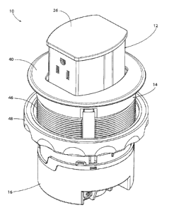
[0019] FIGS. 1 and 2 show an exemplary embodiment of a pop-up outlet
10, having an upper portion including an outlet housing 12, a middle portion
including a terminal housing 14, and a lower portion including a wiring
housing 16. The outlet housing 12 includes a cavity or chamber for receiving
at least a portion of an outlet, the terminal housing 14 includes a cavity or
chamber for receiving at least a portion of a terminal device and conductors
extending from the terminal device to the outlet, and the wiring housing 16
includes a cavity or chamber for receiving at least a portion of wiring
extending from an external source into the pop-outlet.
[0020] A raise/lower mechanism 18 extends through the terminal chamber
to raise and lower the outlet housing 12 with respect to the terminal housing
14. The raise/lower mechanism 18 includes a translating 20 member that
moves between an extended position (as shown) and a retracted position (not
shown). The raise/lower mechanism 18 can be completely manual, include a
biasing member, or include automated components such as a motor, threads,
3
CA 2971768 2017-06-22
gears, telescopic members or other components as would be understood by
one of ordinary skill in the art.
[0021] In various exemplary embodiments, the outlet and a platform 24
are positioned in the outlet housing 12 and a cover 26 is releasably connected
to the outlet housing 12, for example through a snap-fit connection. As shown
in FIGS. 4-6, the outlet housing 12 includes a first snap-fit connection
member
and the cover 26 includes a second snap-fit connection member configured to
mate with the first snap fit connection member. In an exemplary embodiment,
the outlet housing 12 includes first and second openings having a resilient
tab
28. The cover 26 includes first and second protrusions 30 that snap-fit into
the openings. The protrusions 30 can be cantilever beam having a catch or
hook member. The cover 26 can also include one or more posts 32 extending
into the outlet housing 12.
[0022] The outlet includes an outlet body 34 that is connected to the
platform 24, for example through a snap-fit connection. The platform 24 can
include one or more openings with a resilient tab that respectively receives
one or more flexible prongs from the outlet body. The outlet includes
openings for receiving a plug or other type of connector. A three-prong
opening having, hot, neutral, and ground receptacles are shown, although the
outlet can include a two-prong outlet, a USB outlet, or any other type of
electrical connector outlet as would be understood by one of ordinary skill in
the art. The outlet will include various other internal components as would
be understood by one of ordinary skill in the art.
[0023] According to various exemplary embodiments, a gasket or seal 36 is
positioned around the outlet body 34 to resist or prevent liquids from
entering
the outlet body 34 and negatively impacting the electrical components of the
outlet. FIGS. 7 and 8 show and exemplary embodiment of the seal 36. The
seal 36 covers the front, back, sides and top of the outlet body 34. The seal
36
can include openings or slits (not shown) positioned and sized to align and
match the connector openings of the outlet. The slits can be resiliently
biased
¨ 4 ¨
CA 2971768 2017-06-22
to a closed position, but capable of moving to receive a connector, for
example
the prongs of a plug.
[0024] The terminal chamber includes an upper portion for receiving the
outlet housing 12 in the retracted position. An upper plate 38 is connected to
the terminal housing 14 and an upper flange 40 is releasably connected to the
upper plate 38. As shown in FIGS. 4-6, the upper plate 38 includes a first
snap-fit connection member and the flange 40 includes a second snap-fit
connection member configured to mate with the first snap fit connection
member. In an exemplary embodiment, the flange 40 includes a set of four
protrusions 42 that snap-fit into the openings. The protrusions 42 can be
cantilever beam having a catch or hook member. The flange 40 can also
include one or more posts 44.
[0025] An outer surface of the terminal housing includes an outer thread
46. A ring 48 having an inner thread is threadably connected to the outer
thread 46. The pop-up outlet 10 can be positioned in a support, such as a
countertop, with the flange 40 engaging a top surface. The ring 48 is adjusted
and tightened to engage the bottom surface. Adjusting the ring 48 allows the
device to be installed in supports having different depths. The ring 48
includes a gasket to create a seal between the ring and the bottom surface of
the support.
[0026] A terminal block 50 is positioned in the pop-up outlet io with a top
portion in communication with the terminal chamber and a bottom portion in
communication with the wiring chamber. One or more conductors 52 extend
from the terminal block 50 to the outlet body 34 to electrically connect the
outlet with a power supply.
[0027] As best shown in FIGS. 9 and 10, the top portion of the terminal
block 50 includes a set of openings 54, for example a hot opening, a neutral
openings, and a ground opening. The openings are positioned near strain
relief members 56. Conductors 52 can extend through the openings 54 and be
received in the strain relief members 56. The strain relief members 56 reduce
- 5
CA 2971768 2017-06-22
or eliminate strain on the conductors as the outlet is raised and lowered,
helping to prevent disconnection of the conductors.
[0028] In an exemplary embodiment, the strain relief members include a
base 56 and a releasable clip 58. The base 56 includes a channel for receiving
the conductors a set of side projections or barbs. The clips 58 include a pair
of
side openings that receive the barbs in a snap-fit connection.
[0029] As best shown in FIG. ii, the lower portion of the terminal block 50
includes a set of wiring terminals, for example a hot, neutral, and ground
wiring terminal. The wiring terminals can include an opening 6o positioned
orthogonal to a fastener 62, such as a screw, and a moveable plate for
clamping an exposed end of a conductor that is inserted into the opening 60.
Different types of connections, including crimps and other fasteners can also
be used.
[0030] As best shown in FIG. 2, the wiring housing includes different
passages for receiving different types of power supply conductors or conduits.
For example, a knock-out 64 is provided to receive a metallic cable or
conduit.
A strain relief member 66 having a pair of fasteners and a moveable strain
relief plate can be provided for non-metallic cables.
[0031] The foregoing detailed description of the certain exemplary
embodiments has been provided for the purpose of explaining the general
principles and practical application, thereby enabling others skilled in the
art
to understand the disclosure for various embodiments and with various
modifications as are suited to the particular use contemplated. This
description is not necessarily intended to be exhaustive or to limit the
disclosure to the exemplary embodiments disclosed. Any of the embodiments
and/or elements disclosed herein may be combined with one another to form
various additional embodiments not specifically disclosed. Accordingly,
additional embodiments are possible and are intended to be encompassed
within this specification and the scope of the appended claims. The
¨ 6
CA 2971768 2017-06-22
specification describes specific examples to accomplish a more general goal
that may be accomplished in another way.
[0032] As used in this application, the terms "front," "rear," "upper,"
"lower," "upwardly," "downwardly," and other orientational descriptors are
intended to facilitate the description of the exemplary embodiments of the
present disclosure, and are not intended to limit the structure of the
exemplary embodiments of the present disclosure to any particular position or
orientation. Terms of degree, such as "substantially" or "approximately" are
understood by those of ordinary skill to refer to reasonable ranges outside of
the given value, for example, general tolerances associated with
manufacturing, assembly, and use of the described embodiments.
CA 2971768 2017-06-22