Note: Descriptions are shown in the official language in which they were submitted.
ADJUSTABLE PULLEY ASSEMBLY FOR A COMPOUND
ARCHERY BOW
BACKGROUND
[0001] The field of the present invention relates to a pulley assembly for a
compound
archery bow. In particular, an adjustable pulley assembly is disclosed herein
having an ,
adjustable cable deflector on a draw cable pulley for providing fine
adjustment of an
effective length of a cable of the archery bow.
[0002] Several adjustable pulley assemblies are available for compound archery
bows.
Some examples are disclosed in: U.S. Pat. No. 8,020,544 entitled "Archery bow
with
force vectoring anchor" issued 09/20/2011 to McPherson; U.S. Pat. No.
8,082,910
entitled "Pulley assembly for a compound archery bow" issued 12/27/2011 to
Yehle;
U.S. Pat. No. 9,347,730 entitled "Adjustable pulley assembly for a compound
archery
bow" issued 05/24/2016 to Obteshka; U.S. Pat. No. 9,417,028 entitled
"Adjustable
pulley assembly for a compound archery bow" issued 08/16/2016 to Hyde et al.;
U.S.
Pat. No. 9,441,907 entitled "Adjustable pulley assembly for a compound archery
bow"
issued 09/13/2016 to Obteshka; and U.S. Pat. No. 9,506,714 entitled
"Adjustable pulley
assembly for a compound archery bow" issued 11/29/2016 to Eacker et al.
SUMMARY
[0003] A pulley assembly for a compound archery bow comprises a draw cable
pulley,
a power cable pulley substantially rigidly attached to the draw cable pulley,
and an
adjustable cable deflector substantially rigidly attached to the draw cable
pulley. The
draw cable pulley is structurally arranged so as to (i) define a first pulley
assembly
.. transverse rotation axis, (ii) be mounted on a first limb of an archery bow
to rotate about
the first pulley assembly axis, (iii) let out from a circumferential draw
cable journal of the
draw cable pulley a draw cable of the archery bow when the bow is drawn and
the draw
cable pulley rotates about the first pulley assembly axis, and (iv) include a
power cable
CA 2971900 2018-09-13
2
anchor arranged so as to anchor a power cable of the archery bow. The power
cable
pulley is structurally arranged and positioned on the draw cable pulley so
that during
drawing of the bow, (i) a segment of the anchored power cable that is
displaced from
the power cable anchor is taken up by a circumferential power cable journal of
the
power cable pulley, and (ii) a segment of the anchored power cable that is
immediately
adjacent the power cable anchor does not make contact with the power cable
pulley.
One or both of the cable deflector and the draw cable pulley are structurally
arranged
so as to enable substantially rigid attachment of the cable deflector to the
draw cable
pulley in any one of a set of multiple deflector arrangements.
[0004] For each one of the multiple deflector arrangements, the cable
deflector is
positioned and arranged (i) so as to deflect laterally the adjacent segment of
the power
cable by a corresponding amount relative to an undeflected power cable path
from the
power cable anchor, (ii) so that each corresponding amount of lateral
deflection differs
from the corresponding amount of lateral deflection for at least one other of
the multiple
deflector arrangements, and (iii) so that each corresponding amount of lateral
deflection
remains substantially constant throughout drawing of the bow.
[0005] A method for adjusting the pulley assembly described above comprises
moving
the cable deflector from a first one of the multiple deflector arrangements
and
substantially rigidly attaching the cable deflector to the draw cable pulley
in a second,
different one of the multiple deflector arrangements, thereby altering the
amount of
deflection of the adjacent segment of the power cable. Differing amounts of
deflection
of the adjacent segment of the power cable result in (i) differing effective
lengths of the
power cable, and (ii) differing relative synchronizations (with the bow at
brace) of the
pulley assembly with a second pulley assembly mounted on a second limb of the
compound archery bow. The method can be performed without derigging the bow
and
in some instances without using a bow press.
[0006] An archery bow comprises a central riser, first and second bow limbs
secured
to opposing ends of the riser, first and second pulley assemblies rotatably
mounted on
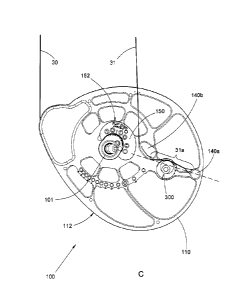
the first and second bow limbs, respectively, a draw cable, and a power cable.
One or
both of the pulley assemblies are arranged as described above.
CA 2971900 2018-09-13
3
[0007] Objects and advantages pertaining to pulley assemblies for compound
bows
may become apparent upon referring to the example embodiments illustrated in
the
drawings and disclosed in the following written description or appended
claims, and
shall fall within the scope of the present disclosure.
[0008] This summary is provided to introduce a selection of concepts in a
simplified
form that are further described below in the Detailed Description. This
Summary is not
intended to identify key features or essential features of the claimed subject
matter, nor
is it intended to be used as an aid in determining the scope of the claimed
subject
matter.
BRIEF DESCRIPTION OF THE DRAWINGS
[0009] Fig. 1 illustrates schematically an example of a so-called dual cam
archery bow
incorporating an example inventive pulley assembly.
[0010] Fig. 2 illustrates schematically an example of a so-called binary cam
archery
bow incorporating an example inventive pulley assembly.
[0011] Fig. 3 illustrates schematically an example of a so-called solo cam
archery bow
incorporating an example inventive pulley assembly.
[0012] Fig. 4 illustrates schematically an example of a so-called hybrid cam
archery
bow incorporating an example inventive pulley assembly.
[0013] Figs. 5A-5C are schematic side views of an example inventive pulley
assembly
in three different example arrangements with the bow at brace.
[0014] Figs. 6A-6C are schematic side views of an example inventive pulley
assembly
in the three different example arrangements of Figs. 5A-5C, respectively, with
the bow at full draw.
[0015] Figs. 7A through 7D are schematic top, front, side, and perspective
views,
respectively, of an example cable deflector.
[0016] Figs. 8A and 8B illustrate schematically one example of mechanically
indexed
engagement of an example cable deflector with an example draw cable pulley.
CA 2971900 2018-09-13
4
[0017] Figs. 9A and 9B are schematic side views of another example inventive
pulley
assembly with the bow at brace and full draw, respectively.
[0018] It should be noted that the embodiments depicted are shown only
schematically, and that not all features may be shown in full detail or in
proper
proportion. Certain features or structures may be exaggerated relative to
others for
clarity. It should be noted further that the embodiments shown are examples
only, and
should not be construed as limiting the scope of the present disclosure or
appended
claims.
DETAILED DESCRIPTION OF EMBODIMENTS
[0019] A compound archery bow comprises a central riser 10, first and second
bow
limbs 11 and 12 secured to opposing ends of the riser 10, first and second
pulley
assemblies 100 and 200 rotatably mounted on the first and second bow limbs 11
and
12, respectively, a draw cable 30, and a power cable 31. If the bow is a so-
called dual
cam bow (Fig. 1) or a so-called binary cam bow (Fig. 2), then the bow includes
a
second power cable 32 and the first and second pulley assemblies 100 and 200
are
substantially identical or substantial mirror images of each other. Upon
drawing a dual
cam bow, the draw cable 30 is let out by both pulley assemblies 100 and 200,
the
power cable 31 (which is attached, directly or indirectly, to the second bow
limb 12) is
taken up by the first pulley assembly 100, and the second power cable 32
(which is
attached, directly or indirectly, to the first bow limb 11) is taken up by the
second pulley
assembly 200. Upon drawing a binary cam bow, the draw cable 30 is let out by
both
pulley assemblies 100 and 200, the power cable 311s let out by the second
pulley
assembly 200 and taken up by the first pulley assembly 100, and the second
power
cable 32 is let out by the first pulley assembly 100 and taken up by the
second pulley
assembly 200.
[0020] If the bow is a so-called solo cam bow (Fig. 3), then the second pulley
assembly 200 comprises an idler wheel and the draw cable 30 passes around the
idler
wheel and is connected at both ends to the first pulley assembly 100. Upon
drawing a
solo cam bow, the both ends of the draw cable are let out by the first pulley
assembly
CA 2971900 2018-09-13
=
100. The power cable 31 is taken up at its first end by the first pulley
assembly 100; the
second end of the power cable 31 typically is attached, directly or indirectly
to the
second bow limb 12; in some examples the power cable 31 instead can be let out
by
the second pulley assembly 200. If the bow is a so-called hybrid cam bow (Fig.
4), then
5 the bow includes an additional coupling cable 33 connected to the first
and second
pulley members 100 and 200. Upon drawing a hybrid cam bow, the draw cable 30
is let
out by both pulley assemblies 100 and 200 and the coupling cable 33 is let out
by the
first pulley assembly 100 and taken up by the second pulley assembly 200. The
power
cable 31 is taken up at its first end by the first pulley assembly 100; the
second end of
the power cable 31 typically is attached, directly or indirectly to the second
bow limb 12;
in some examples the power cable 31 instead can be let out by the second
pulley
assembly 200.
[0021] The inventive pulley assemblies disclosed herein, or equivalents
thereof, can
be advantageously employed with any type of compound archery bow, including
dual
cam, binary cam, solo cam, and hybrid cam bows described above. In a dual or
binary
cam bow, inventive pulley assemblies can be employed for both pulley
assemblies; in a
solo or hybrid cam bow, an inventive pulley assembly can be employed for only
one
pulley assembly, or in some instances of a hybrid cam bow for both pulley
assemblies.
[0022] An example of an inventive pulley assembly 100 is shown in Figs. 5A
through
5C (with the bow 10 at brace) and Figs. 6A through 6C (with the bow 10 at full
draw). As
noted above, the pulley assembly 200 in a dual or hybrid cam bow can be
substantially
identical or a substantial mirror image of the pulley assembly 100, and the
following
description can apply to both pulley assemblies 100 and 200 in such cases. The
pulley
assembly 100 comprises a draw cable pulley 110, a power cable pulley 150
substantially rigidly attached to the draw cable pulley 110, and a cable
deflector 300
substantially rigidly attached to the draw cable pulley 110. Each of those
elements can
be fabricated in any suitable way from any one or more suitably strong and
rigid
materials; such elements are commonly fabricated by machining from aluminum;
other
materials or fabrication methods can be employed. The draw cable pulley 110
defines a
first pulley assembly transverse rotation axis 101 and is mounted on the limb
11 in any
suitable manner to rotate about the first pulley assembly axis 101.
"Transverse" in the
CA 2971900 2018-09-13
=
6
context of the present disclosure refers to a direction that is substantially
perpendicular
to a virtual plane in which the draw cable 30 moves as the bow is drawn; the
first pulley
assembly axis 101 is substantially perpendicular to that draw cable plane.
Suitable
mounting arrangements can include one or more of, e.g., an axle passing
through the
draw cable pulley 110, one or more axle segments integrally formed on the draw
cable
pulley 110, rotational bearings on the draw cable pulley 110 or on the limb
11, and so
on; some examples are disclosed by U.S. Pat. Nos. 8,469,013 and 8,739,769. The
draw cable pulley 110 includes a circumferential draw cable journal or groove
112
arranged around at least a portion of its periphery.
[0023] A first end of the draw cable 30 is secured to the draw cable pulley
110 and
received in the draw cable journal 112. The draw cable pulley 110 lets out the
first end
of the draw cable 30 from the draw cable journal 112 when the bow is drawn and
the
draw cable pulley 110 rotates about the first pulley assembly axis 101. The
draw cable
pulley 110 can be eccentrically mounted (relative to the first pulley assembly
axis 101)
or non-circular so as to act as a cam as it lets out the draw cable 30.
[0024] The power cable pulley 150 is substantially rigidly attached to the
draw cable
pulley 110 in any suitable manner. In some examples, the draw cable pulley 110
and
the power cable pulley 150 can be integrally formed; in other examples the
draw cable
pulley 110 and the power cable pulley 150 can be formed as separate parts and
then
assembled together in any suitable way (directly attached, or attached using
an
intermediate mounting member). In those examples having separate draw cable
and
power cable pulleys 110/150, the draw cable pulley 110 and the power cable
pulley 150
can be attached in only a single fixed arrangement (i.e., relative position
and
orientation), or one or both of the draw cable pulley 110 or the power cable
pulley 150
(or a mounting member, if employed) can be structurally arranged so as to
enable
substantially rigid attachment of the power cable pulley 150 to the draw cable
pulley
100 in any one of multiple power cable pulley arrangements (i.e., relative
position or
orientation). Each one of those multiple power cable pulley arrangements can
result in
one or more of: (i) a corresponding draw length of the bow that differs from a
draw
length resulting from at least one different power cable pulley arrangement;
(ii) a
corresponding draw weight of the bow that differs from a draw weight resulting
from at
CA 2971900 2018-09-13
7
least one different power cable pulley arrangement; (iii) corresponding stored
energy of
the drawn bow that differs from stored energy of the drawn bow resulting from
at least
one different power cable pulley arrangement; or (iv) a corresponding
dependence of
draw force on draw distance of the bow that differs from a dependence of draw
force on
draw distance resulting from at least one different power cable pulley
arrangement.
Examples are disclosed in co-owned U.S. Pat. Nos. 9,347,730 and 9,417,028 and
co-owned U.S. Pat. No. 9,506,714.
[0025] The power cable pulley 150 has a circumferential power cable journal or
groove
152 arranged around at least a portion of its periphery. The power cable
pulley 150 is
113 structurally arranged so as to receive the power cable 31 in the
circumferential power
cable journal 152 and to take up the power cable 31 when the bow is drawn and
the
draw cable pulley 110 rotates about the first pulley assembly axis 101. In
some
examples the power cable pulley 150 has two circumferential grooves (e.g., as
in U.S.
non-provisional App. No. 15/091,572); which groove lets out the power cable 31
depends on the orientation of power cable pulley 150 when it is attached to
the draw
cable pulley 110. The power cable pulley 150 typically is eccentrically
mounted (relative
to the first pulley assembly axis 101) or non-circular so as to act as a cam
as it takes up
the power cable 31. Some examples of suitable arrangements are disclosed in
co-owned U.S. Pat. Nos.: 7,305,979; 7,770,568; 8,181,638; 8,469,013;
8,739,769;
9,347,730; 9,417,028; and 9,441,907, and also in co-owned U.S. Pat No.
9,506,714.
[0026] The draw cable pulley 110 is structurally arranged so as to include a
power
cable anchor 140a. In the example shown, an end loop of the power cable 31 is
placed
on the power cable anchor 140a (in the form of a primary post), and the power
cable 31
spans the distance between the power cable anchor 140a and a secondary post
140b
and at least partly wraps around the secondary post 140b. In the example
shown, the
segment 31a of the power cable 31 between the anchor 140a and the post 140b
does
not move relative to the draw cable pulley 110 as the bow is drawn. Other
suitable
arrangements of the anchor can be employed, e.g., only a single post for
anchoring a
power cable end loop, or a primary post and multiple secondary posts around
which the
power cable 31 is at least partly wrapped. Whatever the specific arrangement
of the
power cable anchor 140a, one or more secondary posts 140b (if any), and the
power
CA 2971900 2018-09-13
8
cable pulley 150, there is a segment 31a of the power cable 31 adjacent the
anchor
140a (i.e., beginning at the anchor 140a) that does not move relative to the
draw cable
pulley 110 throughout drawing of the bow ("throughout" including at brace, at
full draw,
and all intermediate draw distances).
=
[0027] In the example shown, with the bow 10 at brace and also during an
earlier
phase of drawing the bow 10, the power cable pulley 150 is arranged so that it
does not
make contact with any portion of the power cable 31. At some intermediate
point of the
bow's draw, the power cable pulley makes contact with the power cable 31.
After that
point, during a later phase of drawing the bow, a segment of the power cable
31 that is
.. displaced from the power cable anchor 140a (i.e., that is farther away from
the anchor
140a along the power cable 31 than the adjacent segment 31a) is taken up by
the
circumferential power cable journal 152 of the power cable pulley 150, while
the
segment 31a of the power cable that is immediately adjacent the power cable
anchor
140a remains stationary relative to the draw cable pulley 110 throughout the
drawing of
the bow. In another example (not shown), the power cable 31 is in contact with
the
power cable pulley 150 at brace and throughout drawing of the bow as the
displaced
power cable segment is taken up in the groove 152. In such an example, the
adjacent
segment 31a can span the distance between the anchor 140a and the draw cable
pulley 150 (with or without any intermediate post 140b) and remain stationary
.. throughout drawing of the bow.
[0028] One or both of the cable deflector 300 and the draw cable pulley 110
are
structurally arranged so as to enable substantially rigid attachment of the
cable
deflector 300 to the draw cable pulley 110 in any one of a set of multiple
deflector
arrangements. Three such deflector arrangements are shown in Figs. 5A-50 (with
the
bow 10 at brace) and in Figs. 6A-6C (with the bow 10 at full draw). For each
one of the
multiple deflector arrangements, the cable deflector 300 is positioned and
arranged so
as to deflect laterally the adjacent segment 31a of the anchored power cable
31 by a
corresponding amount (relative to an undeflected power cable path from the
power
cable anchor 140a, i.e., the undeflected path between the power cable anchor
140a
and the secondary post 140b in the example shown; the undeflected path is
indicated
by the dashed line in Figs. 5A-50 and 6A-6C). Each corresponding amount of
lateral
CA 2971900 2018-09-13
=
9
deflection differs from the corresponding amount of lateral deflection for at
least one
other of the multiple deflector arrangements. In addition, each corresponding
amount of
lateral deflection remains substantially constant throughout drawing of the
bow,
because the cable deflector 300 is positioned to deflect that segment 31a of
the power
.. cable 31 that remains stationary throughout drawing of the bow.
[0029] The cable deflector 300 can in some examples be arranged so that, for
at least
one of the multiple deflector arrangements, the cable deflector 300 causes no
lateral
deflection, or only negligible lateral deflection, of the adjacent segment 31a
of the
power cable 31 (i.e., the corresponding amount of lateral deflection is about
zero; e.g.,
.. as in Figs. 5A and 6A). In some examples, the cable deflector 300 is
positioned and
arranged so that, in two or more of the multiple deflector arrangements, the
adjacent
segment 31a of the power cable 31 is deflected laterally by differing non-
negligible
amounts (e.g., the deflector arrangement of Figs. 5B and 6B versus the
deflector
arrangement of Figs. 5C and 6C). A non-negligible amount of deflection of the
adjacent
segment 31a effectively shortens the power cable 31, relative to its effective
length in
the absence of lateral deflection (or with only negligible lateral
deflection). Because the
lateral deflection remains substantially constant throughout drawing of the
bow, the
effective length of the power cable 31 also remains constant throughout
drawing of the
bow.
[0030] The arrangement of the inventive pulley assembly 10 should be
contrasted with
that of the pulley assembly disclosed in co-owned Pat. No. 9,441,907
(hereinafter
referred to as the '907 pulley assembly), which also includes a cable
deflector for
deflecting laterally a segment of the power cable by varying amounts. However,
the
'907 pulley assembly is positioned so that, at brace, it does not to make
contact with the
power cable. Only after an initial portion of drawing of the bow does the
power cable
make contact with the cable deflector of the '907 pulley assembly, which then
causes
lateral deflection of the power cable only during a later portion of drawing
of the bow.
Therefore, the amount of lateral deflection of the power cable by the cable
deflector of
the '907 pulley assembly (and therefore the effective length of the power
cable) varies
during drawing of the bow. As noted above, in the inventive pulley assembly,
the lateral
deflection of the segment 31a of the power cable 31 (and therefore its
effective length)
CA 2971900 2018-09-13
=
remains substantially constant throughout drawing of the bow. That distinction
produces
significant differences in the effect of adjusting the cable deflector between
the two
pulley assemblies, i.e., between the inventive pulley assembly disclosed and
claimed
herein and the '907 pulley assembly.
5 [0031] One example of a cable deflector 300 is illustrated schematically
in Figs.
7A-7D. In that example, the cable deflector 300 comprises a lower deflector
member
301 and an upper deflector member 302. Those can be integrally formed or can
be
separate parts assembled together. The upper deflector member 302 can take the
form
of a pin, rod, post, knob, lug, disk, or other suitably shaped member that is
substantially
10 .. rigidly, eccentrically mounted on the lower deflector member 301. In the
example
shown, the lower deflector member 301 comprises a substantially circular disk
that fits
into a corresponding circular cavity 113 on the draw cable pulley 110 (Fig.
8A). The
cable deflector 300 is substantially rigidly attached to the draw cable pulley
110 with the
lower deflector member 301 positioned in the cavity 113 and the upper
deflector
member 302 protruding from the cavity 113 so as to enable the upper deflector
member
302 to deflect the segment 31a of the power cable 31. The circular lower
deflector
member 301, the circular cavity 113, and the eccentric position of the upper
deflector
member 302 on the circular lower deflector member 301, together result in
movement
of the upper deflector member 302 relative to the draw cable pulley 110 as the
cable
.. deflector 300 is rotated (as in Figs 5A through 5C, or Figs. 6A through
6C). Each
different relative rotational position of the lower deflector member 301
within the cavity
113 corresponds to a different deflector arrangement. A screw or other
suitable fastener
can be employed to fix the cable deflector's position once a rotational
position is
selected and the cable deflector 300 is rotated to that selected position.
[0032] Any other suitable arrangement can be employed for implementing a cable
deflector 300, including, e.g.: a translatable or rotatable member deflector
member
slidable along a flat surface of the draw cable pulley 110 or movable along a
slot,
groove, spline, ribs, or track or groove on the draw cable pulley 110. Any
suitable
fastener can be employed to fix the cable deflector's position once a position
or
.. orientation is selected and the cable deflector 300 is moved to that
selected position.
CA 2971900 2018-09-13
=
11
[0033] In some examples, the set of multiple deflector arrangements comprises
a
continuous range of positions or orientations of the cable deflector 300
relative to the
draw cable pulley 110. In the example of Figs. 7A-7D, the circular shape of
the lower
deflector member 301 can permit a continuous range of relative orientations of
the
cable deflector 300 in the round cavity 113 of the draw cable pulley 110. In
other
examples, the set of multiple deflector arrangements comprises a set of
discrete
positions or orientations of the cable deflector 300 relative to the draw
cable pulley 110.
In some of those latter examples, the draw cable pulley 110 or the cable
deflector 300
can be structurally arranged so as to provide mechanical indexing of each one
of the
multiple, discrete positions or orientations of the cable deflector 300
relative to the draw
cable pulley 110. Such indexing can be implemented in any suitable way, e.g.,
a series
of holes for fasteners, pins, or posts, a series of slots, ribs, splines, or
grooves, and so
on. In the example shown in Figs. 8A/8B, the cavity 113 includes a set of
holes 114 and
the lower deflector member 301 includes a corresponding mating set of mating
pins
314. The holes 114 and pins 314 are structurally arranged so as to
mechanically index
a set of multiple, discrete relative rotational positions of the lower
deflector member 301
within the cavity 113. A set of continuous positions/orientations can provide
finer
adjustment of the amount of cable deflection. A set of discrete
positions/orientations,
particularly with mechanical indexing, can provide more reproducible
adjustment, and
can increase resistance of the cable deflector to unwanted movement due to
lateral
forces applied by the deflected cable 31.
[0034] A method for adjusting the pulley assembly 100 comprises moving the
cable
deflector 300 from a first one of the multiple deflector arrangements and
substantially
rigidly attaching the cable deflector 300 to the draw cable pulley 110 in a
second,
different one of the multiple deflector arrangements, thereby altering the
amount of
deflection of the adjacent segment 31a of the power cable 31. The differing
amounts of
deflection of the adjacent segment 31a of the power cable 31 result in (i)
differing
effective lengths of the power cable 31 throughout drawing the bow 10, and
(ii) differing
relative synchronizations (with the bow at brace) of the pulley assembly 100
with the
second pulley assembly 200 mounted on the second bow limb 12. Note that the
synchronization of the pulley assemblies with the bow at brace is sometimes
referred to
CA 2971900 2018-09-13
12
as cam timing. The adjustment (i.e., moving the cable deflector 300 to a new
deflector
arrangement and attaching it there to the cable pulley 110) typically can be
performed
without using a bow press and without derigging the bow (i.e., without
removing one or
more cables from the bow), even though the power cable 3115 under tension when
the
bow is rigged and resists lateral deflection. The ability to make the
adjustment without
derigging the bow or using a bow press is highly advantageous, and can be
facilitated
by structurally arranging the cable deflector 300 to engage a torque-applying
tool. In the
example shown, the cable deflector 300 includes a hex socket head 312 for
receiving a
hex head driver or Allen wrench; applying torque with the driver or wrench
enables
rotational adjustment of the cable deflector 300.
[0035] Adjustments performed on the compound bow 10 by moving the cable
deflector
300 offer a number of advantages. Conventionally, to adjust synchronization of
the
pulley assemblies of a compound bow, a bow press had to be employed and the
bow at
least partially derigged to adjust the length of one or more cables (usually
by adding or
subtracting one or more half-twists to or from the cable; adding a half-twist
shortens the
cable while subtracting a half-twist lengthens the cable). However, those half-
twists can
only be added or subtracted by derigging the cable in question, adding or
subtracting
the half-twist, re-rigging the bow, and removing it from the press. The
iterative process
for adjusting cable synchronization was therefore quite tedious and time-
consuming.
.. Adding to the frustration, a half-twist (required to maintain proper
orientation of anchor
loops at the ends of the cable) often proved to be too coarse an increment of
length
adjustment for properly synchronizing the pulley assemblies.
[0036] Using the inventive pulley assembly with the cable deflector 300
provides
several benefits. As described above, the cable deflector 300 can in some
instances be
.. adjusted (i.e., moved among the multiple deflector arrangements and
attached to the
draw cable pulley 110 at a selected one of those arrangements) without
employing the
bow press and without derigging the bow partly or fully. Because in such
circumstances
the cable deflector 300 is adjusted while the power cable 311s under tension,
typically a
torque-applying tool (e.g., a wrench or driver) is employed to adjust the
cable deflector
300. The lateral deflection of the adjacent segment 31a of the power cable 31
also
results in relatively small changes in the effective length of the power cable
31 (with
CA 2971900 2018-09-13
13
more deflection effectively shortening the power cable 31). The adjustments to
the
effective length of the power cable 31 can be much finer by adjusting the
cable
deflector 300, compared to employing half-twists for cable length adjustment.
Even in
examples wherein a bow press is needed to adjust the cable deflector 300, the
finer
adjustment of the power cable effective length enabled by adjustment of the
cable
deflector 300 is still a significant advantage and distinction over
conventional pulley
assemblies. In addition, even if a bow press is needed to adjust the cable
deflector 300,
derigging the power cable 31 is not required, because no twisting of that
cable is
needed. Because the deflected segment 31a of the power cable 31 remains
stationary
throughout drawing of the bow (relative to the pulley assembly 100), the
lateral
deflection provided by the cable deflector 300 (at a given deflector
arrangement) and
the concomitant effective length of the power cable 31 also remain constant
throughout
drawing of the bow.
[0037] As noted in the '907 patent, inherent asymmetries of the bow arise
from, e.g.,
lateral deflection (relative to the draw cable plane) of the bow's various
cables by a
cable guard. Conventionally, because of those asymmetries, typically it has
been
possible to "line up" (i.e., synchronize) the two pulley assemblies of a given
bow at only
one point in their respective rotations (at brace or during drawing of the
bow), by
adjusting the actual length of the power cable 31. Typically that
synchronization is done
with the bow at brace, and under that condition is sometimes referred to a cam
timing.
The inventive pulley assembly 100 of the present disclosure enables finer
adjustment of
that power cable length 31 than is conventionally available by applying half-
twists to the
power cable. Adjustment of the cable deflector 300 can therefore be employed
to "line
up" (i.e., synchronize) the pulley assemblies of a compound bow at brace more
accurately than conventional methods.
[0038] As noted above, the disclosed inventive pulley assemblies can be
employed
with any type of compound archery bow, including dual cam, binary cam, solo
cam, and
hybrid cam bows. In dual or binary cam bows (Figs. 1 and 2, respectively), the
second
pulley assembly 200 (rotatably mounted on limb 12) typically is substantially
identical to
or a substantial mirror image of the first pulley assembly 100 already
described. The
power cable 32 is taken up by the power cable pulley of the second pulley
assembly
CA 2971900 2018-09-13
=
14
200 as the bow is drawn and the second pulley assembly 200 rotates about a
corresponding second pulley assembly axis. The cable deflector of the second
pulley
assembly 200 can be adjusted in the same ways and with the same effect as
disclosed
above for the first pulley assembly 100. If the bow is a binary cam bow (Fig.
2), the
pulley assemblies 100 and 200 each can further comprise a power cable let-out
mechanism 180 (e.g., a concentric or eccentric let-out pulley) substantially
rigidly
coupled to the draw cable pulley 110 or the power cable pulley 150. The power
cable
let-out mechanism 180 is structurally arranged to receive a corresponding one
of the
power cables and let out that power cable (during at least a portion of the
draw) when
the bow is drawn and the pulley assemblies 100 and 200 rotate.
[0039] If the bow is a solo cam bow (Figs. 3), the pulley assembly 100 can
further
comprise a draw cable let-out pulley 190 substantially rigidly coupled to the
draw cable
pulley 110 or the power cable pulley 150. The draw cable let-out pulley 190 is
structurally arranged to receive a second end of the draw cable 30 in a
circumferential
draw cable journal and let out the second end of the draw cable, with the draw
cable
passing around an idler wheel (i.e., the second pulley assembly 200 rotatably
mounted
on the second bow limb 12) when the bow is drawn and the assemblies rotate
about
the corresponding pulley assembly axes. If the bow is a hybrid cam bow (Fig.
4), the
pulley assembly 100 can be arranged in a manner similar to that of a solo cam
bow,
except that the cable received by and let out by the pulley 190 is an
additional coupling
cable 33 that is taken up by the second pulley assembly 200 as the bow is
drawn.
[0040] Some examples of arrangements suitable for dual, binary, solo, or
hybrid cam
bows are disclosed in co-owned U.S. Pat. Nos.: 7,305,979; 7,770,568;
8,181,638;
8,469,013; 8,739,769; 9,347,730; 9,417,028; and 9,441,907, and also in co-
owned U.S.
Pat No. 9,506,714. One or two inventive pulley assemblies disclosed herein
(Le., that
include a cable deflector 300) can be advantageously employed in any of those
examples.
[0041] In some examples, the inventive cable deflector 300 of the present
disclosure
can be advantageously combined with a second cable deflector 400 arranged
according to the '907 patent (i.e., arranged so as to deflect the power cable,
and
CA 2971900 2018-09-13
=
thereby alter its effective length, only during a later portion of drawing of
the bow). One
such example is shown in Figs. 9A (brace) and 9B (full draw). The cable
deflector 300
enables adjustment of the effective length of the power cable 31 so as to
synchronize
the two pulley assemblies of the bow at a first point during drawing of the
bow, typically
5 with the bow at brace. After that adjustment of the cable deflector 300
is made, the
second cable deflector 400 can be adjusted to synchronize the two pulley
assemblies at
a second, different point during the later portion drawing of the bow; in some
instances
that adjustment of the cable deflector 400 can be made to synchronize the two
pulley
assemblies at full draw. In such an inventive adjustment method for
synchronizing the
10 pulley assemblies 100/200 of a compound bow 10, the cable deflector 300
can be
adjusted to "line up" the pulley assemblies 100/200 at brace, and the cable
deflector
400 can be adjusted to "line up" the pulley assemblies 100/200 at full draw.
[0042] In addition to the preceding, the following examples fall within the
scope of the
present disclosure or appended claims:
15 [0043] Example 1. A pulley assembly for a compound archery bow, the
pulley
assembly comprising a draw cable pulley, a power cable pulley substantially
rigidly
attached to the draw cable pulley, and an adjustable cable deflector
substantially rigidly
attached to the draw cable pulley, wherein: (a) the draw cable pulley is
structurally
arranged so as to (i) define a first pulley assembly transverse rotation axis,
(ii) be
mounted on a first limb of an archery bow to rotate about the first pulley
assembly axis,
(iii) let out from a circumferential draw cable journal of the draw cable
pulley a draw
cable of the archery bow when the bow is drawn and the draw cable pulley
rotates
about the first pulley assembly axis, and (iv) include a power cable anchor
arranged so
as to anchor a power cable of the archery bow; (b) the power cable pulley is
structurally
arranged and positioned on the draw cable pulley so that during drawing of the
bow,
(i) a segment of the anchored power cable that is displaced from the power
cable
anchor is taken up by a circumferential power cable journal of the power cable
pulley,
and (ii) a segment of the anchored power cable that is immediately adjacent
the power
cable anchor does not make contact with the power cable pulley; (c) one or
both of the
cable deflector and the draw cable pulley are structurally arranged so as to
enable
CA 2971900 2018-09-13
=
16
substantially rigid attachment of the cable deflector to the draw cable pulley
in any one
of a set of multiple deflector arrangements; and (d) for each one of the
multiple
deflector arrangements, the cable deflector is positioned and arranged (i) so
as to
deflect laterally the adjacent segment of the anchored power cable by a
corresponding
amount relative to an undeflected power cable path from the power cable
anchor, (ii) so
that each corresponding amount of lateral deflection differs from the
corresponding
amount of lateral deflection for at least one other of the multiple deflector
arrangements, and (iii) so that each corresponding amount of lateral
deflection remains
substantially constant throughout drawing of the bow.
[0044] Example 2. The pulley assembly of Example 1 wherein the power cable
pulley
is arranged so that (i) with the bow at brace and during an earlier phase of
drawing the
bow, the power cable pulley does not make contact with the displaced segment
of the
anchored power cable, and (ii) the displaced segment of the anchored power
cable is
taken up by the circumferential power cable journal of the power cable pulley
during
only a later phase of drawing the bow.
[0045] Example 3. The pulley assembly of any one of Examples 1 or 2 wherein,
in two
or more of the multiple deflector arrangements, the cable deflector is
positioned and
arranged so as to deflect laterally the adjacent segment of the power cable by
a non-
negligible amount relative to the undeflected power cable path from the power
cable
anchor, with the non-negligible amount of lateral deflection varying among the
two or
more of the multiple deflector arrangements.
[0046] Example 4. The pulley assembly of any one of Examples 1 through 3
wherein,
in at least one of the deflector arrangements, the cable deflector is
positioned and
arranged so as to cause no lateral deflection, or only negligible lateral
deflection, of the
adjacent segment of the power cable.
[0047] Example 5. The pulley assembly of any one of Examples 1 through 4
wherein
the set of multiple deflector arrangements comprises a set of discrete
positions or
orientations of the cable deflector relative to the draw cable pulley.
[0048] Example 6. The pulley assembly of Example 5 wherein the draw cable
pulley
or the cable deflector is structurally arranged so as to provide mechanical
indexing of
CA 2971900 2018-09-13
=
17
each one of the multiple, discrete positions or orientations of the cable
deflector relative
to the draw cable pulley.
[0049] Example 7. The pulley assembly of any one of Examples 1 through 4
wherein
the set of multiple deflector arrangements comprises a continuous range of
positions or
orientations of the cable deflector relative to the draw cable pulley.
[0050] Example 8. The pulley assembly of any one of Examples 1 through 7
wherein:
(e) the cable deflector comprises an upper deflector member substantially
rigidly,
eccentrically mounted on a substantially circular lower deflector member; (f)
the draw
cable pulley includes a substantially circular cavity sized so as to
accommodate the
lower deflector member of the cable deflector positioned within the cavity;
(g) the cable
deflector is substantially rigidly attached to the draw cable pulley with the
lower deflector
member positioned in the cavity and the upper deflector member protruding from
the
cavity so as to enable the upper deflector member to deflect the power cable;
and
(h) each different relative rotational position of the lower deflector member
within the
cavity corresponds to a different deflector arrangement.
[0051] Example 9. The pulley assembly of Example 8 wherein the cable deflector
is
structurally arranged so as to engage a torque-applying tool, and so that
engagement of
the torque-applying tool with the cable deflector enables use of the torque-
applying tool
to move the cable deflector from the one of the multiple deflector
arrangements to
another one of the multiple deflector arrangements.
[0052] Example 10. The pulley assembly of any one of Examples 8 or 9 wherein
the
cavity and the lower deflector member include respective mating sets of radial
ribs
structurally arranged so as to mechanically index a set of multiple, discrete
relative
rotational positions of the lower deflector member within the cavity.
[0053] Example 11. The pulley assembly of any one of Examples 8 or 9 wherein
the
cavity and the lower deflector member include respective mating sets of pins
or holes
structurally arranged so as to mechanically index a set of multiple, discrete
relative
rotational positions of the lower deflector member within the cavity.
CA 2971900 2018-09-13
=
18
[0054] Example 12. The pulley assembly of any one of Examples 1 through 11
further
comprising a second pulley assembly, wherein: (e) the second pulley assembly
comprises a second draw cable pulley, a second power cable pulley
substantially rigidly
attached to the second draw cable pulley, and a second adjustable cable
deflector
substantially rigidly attached to the second draw cable pulley; (f) the second
draw cable
pulley is structurally arranged so as to (1) define a second pulley assembly
transverse
rotation axis, (2) be mounted on a second limb of the bow to rotate about the
second
pulley assembly axis, (3) let out a draw cable of the archery bow from a
circumferential
draw cable journal of the second draw cable pulley when the bow is drawn and
the
second draw cable pulley rotates about the second pulley assembly axis, and
(4) include a second power cable anchor arranged so as to anchor a second
power
cable of the archery bow; (g) the second power cable pulley is structurally
arranged and
positioned on the second draw cable pulley so that during drawing of the bow,
(1) a
segment of the anchored second power cable that is displaced from the second
power
cable anchor is taken up by a circumferential power cable journal of the
second power
cable pulley, and (2) a segment of the anchored second power cable that is
immediately adjacent the second power cable anchor does not make contact with
the
second power cable pulley; (h) one or both of the second cable deflector and
the
second draw cable pulley are structurally arranged so as to enable
substantially rigid
attachment of the second cable deflector to the second draw cable pulley in
any one of
a set of multiple second deflector arrangements; and (i) for each one of the
multiple
second deflector arrangements, the second cable deflector is positioned and
arranged
(1) so as to deflect laterally the adjacent segment of the anchored second
power cable
by a corresponding amount relative to an undeflected second power cable path
from
the second power cable anchor, (2) so that each corresponding amount of
lateral
deflection of the second power cable differs from the corresponding amount of
lateral
deflection for at least one other of the multiple second deflector
arrangements, and
(3) so that each corresponding amount of lateral deflection of the second
power cable
remains substantially constant throughout drawing of the bow.
[0055] Example 13. The pulley assembly of any one of Examples 1 through 12
wherein the pulley assembly further comprises a cable let-out pulley
substantially rigidly
CA 2971900 2018-09-13
=
=
19
attached to the draw cable pulley or the power cable pulley, wherein the cable
let-out
pulley is structurally arranged so as to let out from a circumferential
journal of the let-out
pulley an additional cable of the archery bow when the bow is drawn and the
draw
cable pulley rotates about the first pulley assembly axis.
[0056] Example 14. The pulley assembly of any one of Examples 1 through 13
wherein one or both of the draw cable pulley and the power cable pulley are
structurally
arranged so as to enable substantially rigid attachment of the power cable
pulley to the
draw cable pulley in any one of multiple power cable pulley arrangements.
[0057] Example 15. The pulley assembly of Example 14 wherein each one of the
multiple power cable pulley arrangements results in one or more of: (i) a
corresponding
draw length of the bow that differs from a draw length resulting from at least
one
different power cable pulley arrangement; (ii) a corresponding draw weight of
the bow
that differs from a draw weight resulting from at least one different power
cable pulley
arrangement; (iii) corresponding stored energy of the drawn bow that differs
from stored
energy of the drawn bow resulting from at least one different power cable
pulley
arrangement; or (iv) a corresponding dependence of draw force on draw distance
of the
bow that differs from a dependence of draw force on draw distance resulting
from at
least one different power cable pulley arrangement.
[0058] Example 16. The pulley assembly of any one of Examples 1 through 15
further
comprising a second adjustable cable deflector substantially rigidly attached
to the draw
cable pulley, wherein: (e) in any one of multiple second deflector
arrangements, with
the bow at brace, the second cable deflector causes no lateral deflection, or
only
negligible lateral deflection, of the power cable; and (f) in one or more of
the multiple
second deflector arrangements, the second cable deflector is positioned and
arranged
so as to deflect laterally, during only a later phase of drawing the bow, the
adjacent
segment of the power cable by a non-negligible amount relative to an
undeflected
power cable path between the adjacent power cable segment and the power cable
pulley, with the non-negligible amount of lateral deflection differing from an
amount of
lateral deflection of at least one other of the multiple deflector
arrangements.
CA 2971900 2018-09-13
= =
[0059] Example 17. A method for adjusting the pulley assembly of Example 16,
the
method comprising: (A) moving the cable deflector from a first one of the
multiple
deflector arrangements and substantially rigidly attaching the cable deflector
to the
draw cable pulley in a second, different one of the multiple deflector
arrangements,
5 thereby altering relative synchronization of the pulley assembly with a
second pulley
assembly mounted on a second limb of the archery bow with the bow at brace,
and
(B) moving the second cable deflector from a first one of the multiple second
deflector
arrangements and substantially rigidly attaching the second cable deflector to
the draw
cable pulley in a second, different one of the multiple second deflector
arrangements,
10 thereby relative synchronization of the pulley assembly with the second
pulley assembly
during a later portion of drawing of the bow.
[0060] Example 18. A method for adjusting the pulley assembly of any one of
Examples 14 through 16, the method comprising moving the power cable pulley
from a
first one of the multiple power cable pulley arrangements and substantially
rigidly
15 attaching the power cable pulley to the draw cable pulley in a second,
different one of
the multiple power cable pulley arrangements, thereby altering one or more of
the draw
weight, the draw length, the stored energy of the drawn bow, or the dependence
of
draw force on draw distance.
[0061] Example 19. A method for adjusting the pulley assembly of any one of
20 Examples 1 through 16, the method comprising moving the cable deflector
from a first
one of the multiple deflector arrangements and substantially rigidly attaching
the cable
deflector to the draw cable pulley in a second, different one of the multiple
deflector
arrangements, thereby altering the amount of deflection of the adjacent
segment of the
power cable.
[0062] Example 20. The method of Example 19 wherein differing amounts of
deflection of the adjacent segment of the power cable result in (i) differing
effective
lengths of the power cable, and (ii) differing relative synchronizations, with
the bow at
brace, of the pulley assembly with a second pulley assembly mounted on a
second limb
of the compound archery bow.
CA 2971900 2018-09-13
=
21
[0063] Example 21. The method of any one of Examples 19 or 20 wherein the
cable
deflector is moved and attached without using a bow press and without
derigging the
bow.
[0064] Example 22. The method of any one of Examples 19 through 21 wherein the
cable deflector is structurally arranged so as to engage a torque-applying
tool, and the
method further comprises engaging the torque-applying tool with the cable
deflector
and using the torque-applying tool to move the cable deflector from one of the
multiple
deflector arrangements to another one of the multiple deflector arrangements.
[0065] Example 23. A compound archery bow, comprising a central riser, first
and
second bow limbs secured to opposing ends of the riser, first and second
pulley
assemblies rotatably mounted on the first and second bow limbs, respectively,
a draw
cable, and a power cable, wherein: (a) the first pulley assembly comprises a
first draw
cable pulley, a first power cable pulley substantially rigidly attached to the
first draw
cable pulley, and a first adjustable cable deflector substantially rigidly
attached to the
first draw cable pulley; (b) the first draw cable pulley is structurally
arranged so as to
(I) define a first pulley assembly transverse rotation axis, (ii) be mounted
on the first
bow limb to rotate about the first pulley assembly axis, (iii) let out from a
circumferential
draw cable journal of the first draw cable pulley the draw cable when the bow
is drawn
and the draw cable pulley rotates about the first pulley assembly axis, and
(iv) include a
first power cable anchor arranged so as to anchor the power cable; (c) the
first power
cable pulley is structurally arranged and positioned on the first draw cable
pulley so that
during drawing of the bow, a segment of the anchored power cable that is
displaced
from the first power cable anchor is taken up by a circumferential power cable
journal of
the first power cable pulley, and (ii) a segment of the anchored power cable
that is
immediately adjacent the first power cable anchor does not make contact with
the first
power cable pulley; (d) one or both of the first cable deflector and the first
draw cable
pulley are structurally arranged so as to enable substantially rigid
attachment of the first
cable deflector to the first draw cable pulley in any one of a set of multiple
first deflector
arrangements; and (e) for each one of the multiple first deflector
arrangements, the first
cable deflector is positioned and arranged (i) so as to deflect laterally the
adjacent
segment of the anchored power cable by a corresponding amount relative to an
CA 2971900 2018-09-13
=
22
undeflected power cable path from the first power cable anchor, (ii) so that
each
corresponding amount of lateral deflection differs from the corresponding
amount of
lateral deflection for at least one other of the multiple first deflector
arrangements, and
(iii) so that each corresponding amount of lateral deflection remains
substantially
constant throughout drawing of the bow.
[0066] Example 24. The bow of Example 23 wherein the power cable pulley is
arranged so that (i) with the bow at brace and during an earlier phase of
drawing the
bow, the first power cable pulley does not make contact with the displaced
segment of
the anchored power cable, and (ii) the displaced segment of the anchored power
cable
is taken up by the circumferential power cable journal of the first power
cable pulley
during only a later phase of drawing the bow.
[0067] Example 25. The bow of any one of Examples 23 or 24 wherein, in two or
more of the multiple first deflector arrangements, the first cable deflector
is positioned
and arranged so as to deflect laterally the adjacent segment of the power
cable by a
non-negligible amount relative to the undeflected first power cable path from
the first
power cable anchor, with the non-negligible amount of lateral deflection
varying among
the two or more of the multiple first deflector arrangements.
[0068] Example 26. The bow of any one of Examples 23 through 25 wherein, in at
least one of the first deflector arrangements, the first cable deflector is
positioned and
arranged so as to cause no lateral deflection, or only negligible lateral
deflection, of the
adjacent segment of the power cable.
[0069] Example 27. The bow of any one of Examples 23 through 26 wherein the
set
of multiple first deflector arrangements comprises a set of discrete positions
or
orientations of the first cable deflector relative to the first draw cable
pulley.
[0070] Example 28. The bow of Example 27 wherein the first draw cable pulley
or the
first cable deflector is structurally arranged so as to provide mechanical
indexing of
each one of the multiple, discrete positions or orientations of the first
cable deflector
relative to the first draw cable pulley.
CA 2971900 2018-09-13
=
23
[0071] Example 29. The bow of any one of Examples 23 through 26 wherein the
set
of multiple first deflector arrangements comprises a continuous range of
positions or .
orientations of the first cable deflector relative to the first draw cable
pulley.
[0072] Example 30. The bow of any one of Examples 23 through 29 wherein: (f)
the
first cable deflector comprises an upper deflector member substantially
rigidly,
eccentrically mounted on a substantially circular lower deflector member; (g)
the first
draw cable pulley includes a substantially circular cavity sized so as to
accommodate
the lower deflector member of the first cable deflector positioned within the
cavity;
(h) the first cable deflector is substantially rigidly attached to the first
draw cable pulley
with the lower deflector member positioned in the cavity and the upper
deflector
member protruding from the cavity so as to enable the upper deflector member
to
deflect the power cable; and (i) each different relative rotational position
of the lower
deflector member within the cavity corresponds to a different first deflector
arrangement.
[0073] Example 31. The bow of Example 30 wherein the first cable deflector is
structurally arranged so as to engage a torque-applying tool, and so that
engagement of
the torque-applying tool with the first cable deflector enables use of the
torque-applying
tool to move the first cable deflector from one of the multiple first
deflector
arrangements to another one of the multiple first deflector arrangements.
[0074] Example 32. The bow of any one of Examples 30 or 31 wherein the cavity
and
the lower deflector member include respective mating sets of radial ribs
structurally
arranged so as to mechanically index a set of multiple, discrete relative
rotational
positions of the lower deflector member within the cavity.
[0075] Example 33. The bow of any one of Examples 30 or 31 wherein the cavity
and
the lower deflector member include respective mating sets of pins or holes
structurally
arranged so as to mechanically index a set of multiple, discrete relative
rotational
positions of the lower deflector member within the cavity.
[0076] Example 34. The bow of any one of Examples 23 through 33 further
comprising a second power cable, wherein: (f) the second pulley assembly
comprises a
second draw cable pulley, a second power cable pulley substantially rigidly
attached to
CA 2971900 2018-09-13
=
24
the second draw cable pulley, and a second adjustable cable deflector
substantially
rigidly attached to the second draw cable pulley; (g) the second draw cable
pulley is
structurally arranged so as to (1) define a second pulley assembly transverse
rotation
axis, (2) be mounted on the second bow limb to rotate about the second pulley
assembly axis, (3) let out the draw cable from a circumferential draw cable
journal of
the second draw cable pulley when the bow is drawn and the second draw cable
pulley
rotates about the second pulley assembly axis, and (4) include a second power
cable
anchor arranged so as to anchor the second power cable; (h) the second power
cable
pulley is structurally arranged and positioned on the second draw cable pulley
so that
during drawing of the bow, (1) a segment of the anchored second power cable
that is
displaced from the second power cable anchor is taken up by a circumferential
power
cable journal of the second power cable pulley, and (2) a segment of the
anchored
second power cable that is immediately adjacent the second power cable anchor
does
not make contact with the second power cable pulley; (i) one or both of the
second
cable deflector and the second draw cable pulley are structurally arranged so
as to
enable substantially rigid attachment of the second cable deflector to the
second draw
cable pulley in any one of a set of multiple second deflector arrangements;
and (j) for
each one of the multiple second deflector arrangements, the second cable
deflector is
positioned and arranged (1) so as to deflect laterally the adjacent segment of
the
anchored second power cable by a corresponding amount relative to an
undeflected
second power cable path from the second power cable anchor, (2) so that each
corresponding amount of lateral deflection of the second power cable differs
from the
corresponding amount of lateral deflection for at least one other of the
multiple second
deflector arrangements, and (3) so that each corresponding amount of lateral
deflection
of the second power cable remains substantially constant with throughout
drawing of
the bow.
[0077] Example 35. The bow of Example 34 wherein: (k) the first pulley
assembly
further comprises a first power cable let-out pulley substantially rigidly
attached to the
first draw cable pulley or the first power cable pulley; (e) the first power
cable let-out
pulley is structurally arranged so as to let out from a circumferential power
cable journal
of the first power cable let-out pulley the second power cable when the bow is
drawn
CA 2971900 2018-09-13
=
=
and the first draw cable pulley rotates about the first pulley assembly axis;
(m) the
second pulley assembly further comprises a second power cable let-out pulley
substantially rigidly attached to the second draw cable pulley or the second
power cable
pulley; and (n) the second power cable let-out pulley is structurally arranged
so as to let
5 out from a circumferential power cable journal of the second power cable
let-out pulley
the first power cable when the bow is drawn and the second draw cable pulley
rotates
about the second pulley assembly axis.
[0078] Example 36. The bow of any one of Examples 23 through 33 wherein the
second pulley assembly includes a power cable let-out pulley that is
structurally
10 arranged so as to let out from a circumferential power cable journal of
the power cable
let-out pulley the power cable when the bow is drawn and the draw cable pulley
rotates
about the first pulley assembly axis.
[0079] Example 37. The bow of any one of Examples 23 through 33 wherein: (f)
the
first pulley assembly further comprises a draw cable let-out pulley
substantially rigidly
15 attached to the first draw cable pulley or the first power cable pulley;
(g) the second
pulley assembly comprises an idler wheel; and (h) the draw cable let-out
pulley is
structurally arranged so as to let out from a circumferential draw cable
journal of the
draw cable let-out pulley a second end of the draw cable, with the draw cable
passing
around the idler wheel, when the bow is drawn and the draw cable pulley
rotates about
20 the first pulley assembly axis.
[0080] Example 38. The bow of any one of Examples 23 through 33 further
comprising a coupling cable, wherein: (f) the first pulley assembly further
comprises a
coupling cable let-out pulley substantially rigidly attached to the first draw
cable pulley
or the first power cable pulley; (g) the second pulley assembly comprises a
second
25 draw cable pulley and a coupling cable take-up pulley; (h) the second
draw cable pulley
is structurally arranged so as to let out from a circumferential draw cable
journal of the
second draw cable pulley the draw cable when the bow is drawn and the second
pulley
assembly rotates about the second pulley assembly axis; (i) the coupling cable
take-up
pulley is structurally arranged so as to take up into a circumferential
coupling cable
journal of the coupling cable take-up pulley a first end of the coupling cable
when the
CA 2971900 2018-09-13
=
26
bow is drawn and the second pulley assembly rotates about the second pulley
assembly axis; and (j) the coupling cable let-out pulley is structurally
arranged so as to
let out from a circumferential coupling cable journal of the coupling cable
let-out pulley a
second end of the coupling cable when the bow is drawn and the first draw
cable pulley
rotates about the first pulley assembly axis.
[0081] Example 39. The bow of any one of Examples 23 through 38 wherein one or
both of the first draw cable pulley and the first power cable pulley are
structurally
arranged so as to enable substantially rigid attachment of the first power
cable pulley to
the first draw cable pulley in any one of multiple first power cable pulley
arrangements.
[0082] Example 40. The bow of Example 39 wherein each one of the multiple
first
power cable pulley arrangements results in one or more of: (i) a corresponding
draw
length of the bow that differs from a draw length resulting from at least one
different first
power cable pulley arrangement; (ii) a corresponding draw weight of the bow
that differs
from a draw weight resulting from at least one different first power cable
pulley
arrangement; (iii) corresponding stored energy of the drawn bow that differs
from stored
energy of the drawn bow resulting from at least one different first power
cable pulley
arrangement; or (iv) a corresponding dependence of draw force on draw distance
of the
bow that differs from a dependence of draw force on draw distance resulting
from at
least one different first power cable pulley arrangement.
[0083] Example 41. The bow of any one of Examples 23 through 40 further
comprising a second adjustable cable deflector substantially rigidly attached
to the first
draw cable pulley, wherein: (f) in any one of multiple second deflector
arrangements,
with the bow at brace, the second cable deflector causes no lateral
deflection, or only
negligible lateral deflection, of the power cable; and (g) in one or more of
the multiple
second deflector arrangements, the second cable deflector is positioned and
arranged
so as to deflect laterally, during only a later phase of drawing the bow, the
adjacent
segment of the power cable by a non-negligible amount relative to an
undeflected
power cable path between the adjacent power cable segment and the first power
cable
pulley, with the non-negligible amount of lateral deflection differing from an
amount of
lateral deflection of at least one other of the multiple deflector
arrangements.
CA 2971900 2018-09-13
=
27
[0084] Example 42. A method for adjusting the bow of Example 41, the method
comprising: (A) moving the first cable deflector from a first one of the
multiple first
deflector arrangements and substantially rigidly attaching the first cable
deflector to the
draw cable pulley in a second, different one of the multiple first deflector
arrangements,
thereby altering relative synchronization of the pulley assembly with the
second pulley
assembly with the bow at brace, and (B) moving the second cable deflector from
a first
one of the multiple second deflector arrangements and substantially rigidly
attaching
the second cable deflector to the first draw cable pulley in a second,
different one of the
multiple second deflector arrangements, thereby altering relative
synchronization of the
first pulley assembly with the second pulley assembly during a later portion
of drawing
of the bow.
[0085] Example 43. A method for adjusting the bow of any one of Examples 39
through 41, the method comprising moving the first power cable pulley from a
first one
of the multiple first power cable pulley arrangements and substantially
rigidly attaching
the first power cable pulley to the first draw cable pulley in a second,
different one of the
multiple first power cable pulley arrangements, thereby altering one or more
of the draw
weight, the draw length, the stored energy of the drawn bow, or the dependence
of
draw force on draw distance.
[0086] Example 44. A method for adjusting the bow of any one of Examples 23
through 41, the method comprising moving the first cable deflector from a
first one of
the multiple first deflector arrangements and substantially rigidly attaching
the first cable
deflector to the first draw cable pulley in a second, different one of the
multiple first
deflector arrangements, thereby altering the amount of deflection of the
adjacent
segment of the power cable.
[0087] Example 45. The method of Example 44 wherein differing amounts of
deflection of the adjacent segment of the power cable result in (i) differing
effective
lengths of the power cable, and (ii) differing relative synchronizations, with
the bow at
brace, of the first pulley assembly with the second pulley assembly mounted on
the
second limb of the compound archery bow.
CA 2971900 2018-09-13
=
28
[0088] Example 46. The method of any one of Examples 44 01 45 wherein the
first
cable deflector is moved and attached without using a bow press and without
derigging
the bow.
[0089] Example 47. The method of any one of Examples 44 through 46 wherein the
first cable deflector is structurally arranged so as to engage a torque-
applying tool, and
the method further comprises engaging the torque-applying tool with the first
cable
deflector and using the torque-applying tool to move the first cable deflector
from one of
the multiple first deflector arrangements to another one of the multiple first
deflector
arrangements.
[0090] It is intended that equivalents of the disclosed example embodiments
and
methods shall fall within the scope of the present disclosure or appended
claims. It is
intended that the disclosed example embodiments and methods, and equivalents
thereof, may be modified while remaining within the scope of the present
disclosure or
appended claims.
[0091] In the foregoing Detailed Description, various features may be grouped
together in several example embodiments for the purpose of streamlining the
disclosure. This method of disclosure is not to be interpreted as reflecting
an intention
that any claimed embodiment requires more features than are expressly recited
in the
corresponding claim. Rather, as the appended claims reflect, inventive subject
matter
may lie in less than all features of a single disclosed example embodiment.
[0092] For purposes of the present disclosure and appended claims, the
conjunction
"or" is to be construed inclusively (e.g., "a dog or a cat" would be
interpreted as "a dog,
or a cat, or both"; e.g., "a dog, a cat, or a mouse" would be interpreted as
"a dog, or a
cat, or a mouse, or any two, or all three"), unless: (i) it is explicitly
stated otherwise, e.g.,
by use of "either... or," "only one of," or similar language; or (ii) two or
more of the listed
alternatives are mutually exclusive within the particular context, in which
case "or" would
encompass only those combinations involving non-mutually-exclusive
alternatives. For
purposes of the present disclosure and appended claims, the words
"comprising,"
"including," "having," and variants thereof, wherever they appear, shall be
construed as
open ended terminology, with the same meaning as if the phrase "at least" were
CA 2971900 2018-09-13
29
appended after each instance thereof, unless explicitly stated otherwise. For
purposes
of the present disclosure or appended claims, when terms are employed such as
"about
equal to," "substantially equal to," "greater than about," "less than about,"
and so forth,
in relation to a numerical quantity, standard conventions pertaining to
measurement
precision and significant digits shall apply, unless a differing
interpretation is explicitly
set forth. For null quantities described by phrases such as "substantially
prevented,"
"substantially absent," "substantially eliminated," "about equal to zero,"
"negligible," and
so forth, each such phrase shall denote the case wherein the quantity in
question has
been reduced or diminished to such an extent that, for practical purposes in
the context
of the intended operation or use of the disclosed or claimed apparatus or
method, the
overall behavior or performance of the apparatus or method does not differ
from that
which would have occurred had the null quantity in fact been completely
removed,
exactly equal to zero, or otherwise exactly nulled.
[0093] In the appended claims, any labelling of elements, steps, limitations,
or other
portions of a claim (e.g., first, second, etc., (a), (b), (c), etc., or (i),
(ii), (iii), etc.) is only
for purposes of clarity, and shall not be construed as implying any sort of
ordering or
precedence of the claim portions so labelled. If any such ordering or
precedence is
intended, it will be explicitly recited in the claim or, in some instances, it
will be implicit
or inherent based on the specific content of the claim.
CA 2971900 2018-09-13