Note: Descriptions are shown in the official language in which they were submitted.
Assembly for Lifting or Supporting a Load, and Members and Connectors for Use
in Same
Technical Field
Provided herein is an assembly for lifting, supporting or distributing a load
and members for use in the
assembly. Also provided are connectors for connecting two or more members in
the assembly.
Background
A spreader bar assembly is a lifting device used to aid in the lifting of
heavy loads. Spreader bar
assemblies re-orient the lifting load to distribute the load across more than
one point. This can increase
stability and decrease the loads applied during hoisting. While spreader bars
are common in the
industry, most are custom made to the exact length required to handle a load
of a given size. However,
custom fabrication is not only expensive but time consuming. Another option
available is to design the
spreader bar assembly so that the end of one bar slides telescopically within
another end or to provide
multiple holes in a bar in the assembly to which a load is supported. Although
such configurations can
simplify adjustment of the length of the spreader bar assembly, a drawback is
that the assemblies are
often heavy and thus difficult for a single person to carry and assemble on-
site. Thus, spreader bar
assemblies are typically transported on large trucks, which can be
inconvenient, and add significant cost.
Assemblies comprising bars or other connecting members can also be used in
other applications besides
spreader bar assemblies to lift, support or re-distribute loads. This includes
applications in which a load
is to be redistributed across more than one point, ranging from shoring frames
to large space frames,
such as frames for light industrial building structures. However, assembling
and disassembling such
structures is subject to the same disadvantages described with reference to
spreader bar assemblies.
Likewise, the members making up the assemblies often need to be custom
fabricated.
Accordingly, it would be advantageous to provide an assembly for lifting,
supporting or distributing a
load that is simple in construction, easy to assemble and adjustable to a
desired dimension or
configuration. The embodiments disclosed herein seek to address the problems
in such known
assemblies or to provide one or more useful alternatives.
1
CA 2972085 2017-06-28
Summary
According to one exemplary embodiment, there is provided an assembly
comprising: a plurality of
members connectable in an assembled arrangement for supporting, carrying or
distributing a load; each
member comprising a first end and a second end, at least one of the first end
and the second end of
each member has a pair of connecting members, each connecting member
comprising two lugs that
have two respective holes therethrough; which pair of connecting members are
configured for
interconnection with a corresponding pair of connecting members formed on
another member in said
assembly for connection thereto, the corresponding pair of connecting members
each comprising two
lugs that have two respective holes therethrough; and fasteners that each
comprise a shaft that extends
through the holes formed in said lugs when the holes in the lugs of each pair
of connecting members
lugs are aligned with the holes in the lugs of the corresponding pair of
connecting members on the other
member.
In one embodiment, the two lugs of each connecting member are horizontally off-
set from one another.
According to another embodiment, there is provided a member for use in an
assembly, said assembly
comprising a plurality of members connectable in an assembled arrangement for
supporting, carrying or
distributing a load, the member for use in said assembly comprising: a first
end and a second end, at
least one of the first end and the second end has a pair of connecting
members, each connecting
member comprising two lugs that have two respective holes therethrough; which
pair of connecting
members are configured for interconnection with a corresponding pair of
connecting members formed
on another member in said assembly for connection thereto by fasteners, the
corresponding pair of
connecting members each comprising two lugs that have two respective holes
therethrough; and the
two lugs on the member for use in said assembly being off-set from one
another.
According to a further embodiment, there is provided a connector element for
connecting two or more
members in an assembly for supporting, carrying or distributing a load, the
connector element
comprising: a central element having at least two pairs of connecting members,
each connecting
member comprising two lugs that have two respective holes therethrough,
wherein the two lugs are off-
set with respect to one another; and which pair of connecting members are
configured for
interconnection with a corresponding pair of connecting members formed on
another member in said
assembly for connection thereto, the corresponding pair of connecting members
each comprising two
lugs that have two respective holes therethrough.
2
CA 2972085 2017-06-28
Brief Description of the Drawings
FIGURE 1A shows a spreader bar assembly according to one embodiment.
FIGURE 1B shows a spreader bar assembly lifting a load.
FIGURE 2A depicts a pair of connecting members on one end of a bar in the
spreader bar assembly.
FIGURE 2B depicts two bars in a spreader bar assembly connected by respective
pairs of connecting
members.
FIGURE 2C is a side view of two bars of the assembly attached via the
connecting members.
FIGURE 2D is a plan view of two bars of the assembly attached via the
connecting members.
FIGURE 2E is a three-dimensional view of two bars of the assembly attached via
the connecting
members and in which a lifting member is attached thereto.
FIGURE 3A is an example of an assembled spreader bar assembly.
FIGURE 3B is another example of an assembled spreader bar assembly.
FIGURE 4A shows a three-way connector element according to one embodiment.
FIGURE 4B is a three dimensional depiction of the three-way connector element.
FIGURE 5A is another example of an assembled spreader bar assembly.
FIGURE 5B shows the spreader bar assembly of Figure 5A in three dimensions
lifting a load.
FIGURE 6A is a four-way connector element according to one embodiment.
FIGURE 6B is a three dimensional depiction of the four-way connector element.
FIGURE 7A is a three dimensional depiction of a six-way connector element.
FIGURE 7B is a three dimensional depiction of the six-way connector element
shown attached to other
members in the assembly.
FIGURE 7C is another three dimensional depiction of the six-way connector
element shown attached to
other members in the assembly.
3
CA 2972085 2017-06-28
FIGURE 7D a side plan view of Figure 7C showing a brace rotatably mounted to a
pin of the connecting
member.
FIGURE 7E is another three dimensional depiction of the six-way connector
element shown attached to
other members in the assembly.
FIGURE 8A shows a spreader bar assembly using the three-way connector.
FIGURE 8B shows the spreader bar assembly of Figure 8A lifting a load.
FIGURE 8C shows another spreader bar assembly using the three-way connector.
FIGURE 9A-9E show various spreader bar assembly configurations encompassed by
embodiments.
FIGURE 10 depicts an extension bracket assembly according to one embodiment.
FIGURE 11 depicts the use of the connecting members for use in assembling bars
that are part of a
building structure or other structure that carries or re-distributes load.
FIGURE 12A depicts the use of six-way connectors for use in assembling bars
that are part of a building
structure or other structure that carries or re-distributes load.
FIGURE 12B depicts another example of the use of the connecting members for
use in assembling bars
that are part of a building structure or other structure that carries or re-
distributes load.
FIGURE 12C depicts another example of the use of the connecting members for
use in assembling bars
that are part of a building structure or other structure that carries or re-
distributes load.
FIGURE 13A shows a two-way connector according to an embodiment.
FIGURE 13B shows a two-way connector according to another embodiment.
FIGURE 13C shows a two-way connector according to further embodiment.
FIGURE 14A shows connecting members having lugs of blocked configuration in
unassembled form.
FIGURE 14B shows the connecting members having lugs of blocked configuration
in assembled form.
FIGURE 15A shows the connecting members having lugs of blocked configuration
with a lifting element
attached thereto.
4
CA 2972085 2017-06-28
FIGURE 158 shows the connecting members having lugs of blocked configuration
with a lifting element
,
in the form of a shackle bracket assembly attached thereto.
FIGURE 16A shows a three-way connector with blocked lugs.
FIGURE 16B shows a four-way connector with blocked lugs.
FIGURE 16C shows a six-way connector with blocked lugs.
FIGURE 17 shows a six-way connector with blocked lugs in assembled form.
FIGURE 18A shows a pair of connecting members that are blocked and elongate.
FIGURE 18B shows a pair of connecting members that are blocked and elongate in
assembled form.
FIGURE 19A shows a six-way connector element comprising connecting members
that are blocked and
elongate.
FIGURE 19B shows a connector having blocked and elongate connecting members on
three faces
thereof.
FIGURE 20A shows an assembled frame for a light industrial building utilizing
plates comprising the
connecting members.
FIGURE 20B is a detailed view of the circled region of Figure 20A.
FIGURE 20C shows a plate depicted in Figure 20B.
FIGURE 21 shows an eight-way connector according to embodiments.
Detailed Description
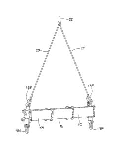
Figure 1A depicts a side plan view of spreader bar assembly 1 according to a
first embodiment. The
spreader bar assembly 1 comprises a plurality of spreader bars 4A, 48 and 4C
connectable in an
assembled arrangement for carrying a load. The assembled arrangement is shown
in Figure 1B.
Each spreader bar 4A, 48 and 4C comprises a first end and a second end,
depicted here by reference
numbers 6A, 6B, 6C, 6D, 6E and 6F. The first and the second end of each
spreader bar 4A, 4B and 4C has
a pair of outwardly extending connecting members, each connecting member
comprising two lugs that
CA 2972085 2017-06-28
each have a hole formed therethrough. This is depicted in Figures 2A-2D, which
shows the circled
region of Figure 1A in more detail.
Figure 2A shows the end of bar 4C of Figure 1A having the two outwardly
extending connecting
members depicted as 8A and 8B. As shown in Figure 2A, there are two lugs, 9A
and 9B, formed on the
connecting member 8A. Likewise, connecting member 8B comprises two lugs 11A
and 11B. Since
connecting members 8A and 8B are of a similar arrangement, for brevity, only
connecting member 8A is
discussed in more detail below.
The lug 9A of connecting member 8A is off-set horizontally with respect to lug
9B by an off-set distance
shown in Figure 2A as d. In this embodiment, a tie 9C is formed between the
two lugs 9A and 9B to
provide continuity between the lugs 9A, 9B. The tie 9C is angled inwardly from
the adjacent edge of the
bar 4C as shown to join lug 9A and lug 9B. The angle of tie 9C with respect to
the adjacent edge of bar
4C is shown as A in the drawing. Such an off-set orientation of the lugs 9A
and 9B on spreader bar 4C
facilitates complementary interconnection with a corresponding pair of lugs on
another spreader bar, as
described further below. As noted above, lugs 11A and 11B and tie 11C of
connecting member 8B are
configured in a similar manner.
Figure 2B shows the pair of connecting members 8A and 86 on the end of bar 4C
connected to a
complementary pair of connecting members 8C and 8D formed on the end of bar 4B
(shown in Figure
1A). The pair of connecting members 8C and 8D each comprises lugs (some of
which are obscured in
the drawing) that are horizontally off-set on the end of bar 4B in a similar
manner as described above for
connecting members 8A and 8B. However, when the connecting members 8A and 8B
are aligned for
connection with corresponding connecting members 8C and 8D, they are oriented
in opposite
configurations as shown in Figure 2B. For example, in the orientation shown in
Figure 2B, the tie 9C of
connecting member 8A is angled inwardly from the top lug 9A to the bottom lug
9B (as described above)
and the corresponding tie 13C of connecting member 8D is angled inwardly from
the bottom lug 13B to
the top lug 13A. Such an orientation allows the lugs 9A and 9B of connecting
member 8A to
interconnect with lugs 13B and 13A of connecting member 8D in a staggered
configuration after
fasteners 10A and 10B are inserted through aligned holes formed in lugs 9A,
9B, 13A and 13B.
Figure 2C is a side view that shows the circled area of Figure 1A in more
detail. Connecting members 8A
and 8D are shown in the drawing, while connecting members 8B and 8C are
obscured from view. Figure
2D is a plan view of Figure 2C. Figure 2E is a three-dimensional depiction of
the two pairs of connecting
6
CA 2972085 2017-06-28
members that connect bars 4B and 4C similar to the drawing of Figure 2B but
showing a shackle 18D
attached via a shackle bracket 16C to fastener 10A. The shackle bracket is
described in more detail
below. Alternatively, a truss diagonal (also referred to herein as a brace)
can be mounted on fastener
10A as shown in Figures 7C and 7D described below. The space between adjacent
lugs through which a
fastener is inserted may be sufficient to accommodate either a shackle bracket
or a truss diagonal. As
will be appreciated by those of skill in the art, other members could be
mounted on the fasteners and
the foregoing embodiments are only illustrative.
In the embodiments depicted in the figures, the fasteners 10A and 10B are
pins. This is shown more
clearly in Figure 2D, which is a side view of the aligned pairs of connecting
members shown in Figure 1A
and Figure 2B. As shown in Figure 2D, the pin is of standard construction and
comprises a shaft 12, a
head 14 and a cotter pin 15 for securing the shaft in place.
Referring again to Figure 1A, the assembly 1 comprises lifting members 16A,
16B, 16C, 16D, 16E and 16F
that are each rotatably attached to a respective shaft of each fastening
element. In this embodiment,
the lifting members 16A, 1613, 16C, 16D, 16E and 16F comprise shackle
brackets. Each lifting member
16A, 16B, 16C, 16D, 16E and 16F is attached to a respective shackle 18A, 18B,
18C, 18D, 18E and 18F.
As depicted in Figure 1B, when the spreader bar is assembled, the spreader
bars 4A, 4B and 4C are
coupled end-to-end in a linear configuration. The shackles 18B and 18E accept
hooks attached to cables
20 and 21. A central cable 22 is attached to a lifting device such as a crane
(not shown). Shackles 18A
and 18F are attached to a load via cables and the like (not shown).
While Figure 1B shows a spreader bar assembly layout in which the spreader
bars are attached end-to-
end, Figure 3A shows an alternative layout in which the spreader bars are
arranged using four three-way
connectors to attach the spreader bars in a square configuration.
As shown in Figure 3A, the assembled spreader bar assembly 2 comprises a
plurality of spreader bars
24A, 24B, 24C, 24D, 24E, 24F, 24G, 24H, 241, 24J, 24K, 24L, 24M, 24N, 240 and
24P. The four corners of
the assembled spreader bar assembly 1 comprise respective three-way connectors
26A, 26B, 26C and
26D.
The three-way connector 26A depicted in Figure 3A is shown in more detail in
Figure 4A (see the circled
region of Figure 3A). As shown in Figure 4A, the three-way connector has three
sides (also referred to as
faces) 28A, 28B and 28C, each comprising pairs of connecting members that in
turn comprise two lugs
7
CA 2972085 2017-06-28
that extend outwardly and are off-set as described. For example, side 28A has
a pair of connecting
members 30A and 30B that connect to similar connecting members on spreader bar
24A via two pins,
one of which is shown as pin 32 in Figure 4A. The other sides 28B and 28C
contain identical connecting
members comprising lugs to connect to complementary lugs on spreader bars 24B
and 24P,
respectively. For simplicity, reference numbers are omitted to describe these
latter elements. Figure 4B
is a three-dimensional depiction of the three-way connector depicted in Figure
4A.
The assembled spreader bar assembly is shown in three-dimension in Figure 3B.
The spreader bar
assembly 2 comprises shackles 32A, 32B, 32C and 32D mounted on respective
shackle brackets that are
rotatably attached to pins in the three-way connector in a same manner as
described with reference to
Figure 2A. The shackles 32A, 32B, 32C and 32D accept hooks attached to cables
34A, 34B, 34C and 34D.
A central cable 36 is attached to a lifting device such as a crane (not
shown). Shackles 38A, 38B, 38C and
38D are attached to a load (not shown). These shackles are part of an
extension bracket assembly,
which is described in more detail below with respect to Figures 8A, 8B and 8C.
Figure 5A shows an alternative layout using a four-way connector to attach the
spreader bars.
As shown in Figure 5A, the assembled spreader bar assembly 3 comprises a
plurality of spreader bars
42A, 42B, 42C, 42D, 42E, 42F, 42G and 42H. The center of the assembled
spreader bar assembly
comprises a four-way connector 44.
The four-way connector 44 depicted in Figure 5A is shown in more detail in
Figure 6A (see the circled
region of Figure 5A). As shown in Figure 6A, the four-way connector has four
sides (or faces) 46A, 46B,
46C and 46D each comprising pairs of connecting members that extend outwardly.
For example, side
46A has a pair of outwardly extending connecting members 484 comprising two
lugs and 48B that
connect to similar, but oppositely oriented connecting members comprising two
lugs in spreader bar
42B via pins, one of which is shown as pin 50 in Figure 6A. In this non-
limiting embodiment, the sides
46B, 46C and 46D contain identical outwardly extending connecting members
comprising lugs to
connect to lugs of connecting members in spreader bars 42C, 42E and 42G,
respectively. For simplicity,
reference numbers are omitted to describe these latter elements. Figure 6B is
a three-dimensional
depiction of the four-way connector shown in Figure 6A.
The assembled spreader bar assembly is shown in Figure 5B. The spreader bar
assembly 3 comprises
shackles 50A, 50B, 50C and 50D mounted on respective shackle brackets that are
rotatably attached to
pins in an extension bracket assembly (described in more detail below). The
shackles 50A, 50B, 50C and
8
CA 2972085 2017-06-28
50D accept hooks attached to cables 52A, 52B, 52C and 52D. A central cable 53
is attached to a lifting
device such as a crane (not shown). Shackles 54A, 54B, 54C and 54D are
attached to a load via cables
(not shown). Although shackles and shackle brackets are described, other
members could be used to
lift a load via cables.
Figure 7A shows a six-way connector, in which each face of the connector
comprises connecting
members having lugs. Connecting members on one face of the six-way connector
are labelled 100 and
102, but the references numbers are omitted on the remainder of the connecting
members comprising
lugs for brevity. Figure 7B shows the six-way connector attached to bars 104,
106, 108 and 110 when
connected in an assembled arrangement. The assembled arrangement in this case
can be a spreader
bar assembly or another structure, such as a building frame as discussed
below. The assembled
arrangement also comprises braces 112, 114, 116 and 118 rotatably attached to
pins connecting the
pairs of opposing lugs formed on the connecting members.
Figure 7C is a three-dimensional isometric section of Figure 7B and like
reference numbers depict
identical parts among the drawings.
Figure 7D a side plan view of Figure 7C showing brace 112 rotatably mounted to
pin 114. As shown in
Figure 7D, brace 112 within the assembled structure has a rotation limit of
around 140 degrees. As
would be appreciated by those of skill in the art, the precise rotation limit
will depend on the
configuration. A rotation limit is advantageous in that such an arrangement
provides increased carrying
capacity and shear capacity of the joint by adding the advantages of truss
action by joining single
members into a two-part unit.
Figure 7E depicts part of an assembled structure 140 using a six-way
connector. In this example, the
braces shown in Figures 7B-7D are omitted. This drawing illustrates the inner
detail through a cut
section.
Figures 8A, 8B and 8C illustrate the versatility of the spreader bar assembly.
As shown, a number of
different configurations can be assembled using the components of the spreader
bar assembly. Figure
8A shows an assembled arrangement using two three-way connectors 26E and 26F.
The three-way
connectors 26E and 26F are the same as described previously in Figure 4A and
thus will not be described
further for brevity. Shackles 56A and 566 connect to cables 58A and 58B,
respectively. A central cable
60 attaches to a loading device. Shackles 62A, 62B, 62C and 62D attach to a
load via cables (not shown).
9
CA 2972085 2017-06-28
Although shackles are shown in the drawings, it should be appreciated that
other means may be used to
,
connect members in the assembly.
Figure 8C shows yet a further configuration comprising the spreader bar
arrangement of Figure 8B, but
with an additional connected spreader bar arrangement 64 comprising two
spreader bars attached end-
to-end. In this embodiment, shackles 65A, 65B, 65C and 65D link to cables 66A,
66B, 66C and 66D,
respectively. Cables 66A, 66B, 66C and 66D link to respective shackles 68A,
68B, 68C and 68D mounted
on spreader bar arrangement 64. Shackles 70A and 70B in turn are linked to
cables 72A and 72B,
respectively. A central cable 74 is attached to a crane.
Figures 9A-9E show yet further spreader bar assembly configurations depicted
as 120, 122, 124, 126 and
128, further demonstrating the versatility of the components in the assembly.
Thus, it is possible to construct a multitude of different configurations
using the components of the
spreader bar assembly. Advantageously, the components of the assemblies can be
easily assembled and
disassembled. In addition, the components can be easily transported, such as
in the box of a pick-up
truck or possibly the trunk of a car. As noted, drawbacks of some of the known
spreader bar assemblies
are lack of versatility and difficulties in transport to and from a site. The
embodiments disclosed herein
address these shortcomings or provide useful alternatives.
Figure 10 depicts an extension bracket assembly 76. The extension bracket
assembly 76 is that depicted
in the circled regions of Figure 3A and Figure 5A. As shown in Figure 10, the
extension bracket assembly
76 is mounted on the end of a spreader bar 78. One end of the spreader bar 78
comprises a pair of
connecting members 80A and 80B comprising respective holes formed in lugs
through which pins are
inserted. The lugs of connecting members 804 and 80B are aligned with a
corresponding pair of lugs in
connecting members 82A and 82B mounted on one side of a plate 84. The pins 864
and 86B are
inserted through aligned holes in the lugs shown in the drawing. An opposing
side of the plate 84
comprises another pair of connecting members 88A and 88B, which each comprise
two lugs with holes
formed therein. A pin 85 is inserted through the lowermost aligned holes.
Shackle brackets 92A and
92B are rotatably mounted on pins 86A and 85, respectively. On shackle
brackets 92A and 92B are
mounted shackles 94A and 94B, respectively. Shackle bracket 92A and shackle
bracket 92B each
comprise a hole through which respective shackles 944 and 94B are mounted via
pins.
The extension bracket assembly 76 can provide for the possibility of attaching
two cables to the terminal
ends of the assembly via two shackles, while maintaining the structural
stability of the assembly by
CA 2972085 2017-06-28
distributing the load. In some instances, it may be desirable to introduce a
small reverse moment in the
spreader bar to limit deflections or increase lifting capacity. However, as
will be appreciated by those of
skill in the art, such extensions can take many forms and the foregoing
embodiment is simply
illustrative. For example, as shown in Figure 3B, two shackles can be attached
to the terminal end of bar
24M.
While Figures 1-10 describe spreader bar assemblies and connectors for use in
same, other bar
assemblies besides those used for lifting loads can be constructed using the
members and connectors
described herein.
For example, Figure 11 depicts an assembly that can be used in other
applications besides a spreader
bar assembly, such as in a building frame. The assembly is constructed from
the four-way connector
depicted in Figure 6A and Figure 6B and comprises cables 134 and 135 for
increased structural stability.
Like reference numbers depict similar or identical parts among the figures.
Shackles 130 and 131 are
mounted on shackle brackets 132 and 137, respectively. The shackle 130 is
connected to a cable 134
and shackle 131 is connected to cable 135.
Figures 12A-12C depict further structures that can be assembled using the six-
way connector. Figures
12A, 12B and 12C show building structures 142, 144 and 146. Each of these
structures comprises braces
attached via shackles to the pins of the six-way connectors to enhance
structural stability. The six-way
connector was previously described in Figure 7A.
Figure 13A shows a two-way connector 149 having a first plate 148 with
connecting members 150 and
152 each comprising a pair of lugs and a second plate 154 with connecting
members 156 and 158 each
comprising a pair of lugs. The central portion of the two-way connector 149
comprises a pair of tongues
160, 162 that are fitted on an opposing tongue 164 disposed on plate 154. The
pair of tongues 160, 162
and the opposing tongue 164 comprise holes through which a pin is inserted
when they are aligned.
Figure 13B depicts an alternate member 163 for use in an assembly comprising a
plate 160 having on
one side a tongue 165 with a hole formed therein and, on the other side, a
pair of connecting members
162, 164 each comprising a pair of lugs. The connecting members 162, 164 are
attached by pins to a
corresponding pair of connecting members 166, 168 comprising lugs on a second
plate 170 to which a
bar 172 is connected. The tongue 165 can be secured to a building or other
structure via a pin or other
fastener that fits through the hole formed in the tongue. Assembly 163 could
be used as a crane tie
11
CA 2972085 2017-06-28
down or as part of a building structure. As will be appreciated by those of
skill in the art, tongues 160,
162 and 164 can take several forms and thus are simply illustrative of non-
limiting embodiments.
Figure 13C depicts an assembly 176 that is similar to the one depicted in
Figure 13B, except a clamp 174
replaces the tongue 165. Some of the reference numbers are omitted for
brevity. Otherwise, identical
reference numbers are used in Figure 13B and 13C.
Figure 14A depicts an embodiment having a connecting member with a lug design
that differs from that
described in Figures 1-13, but its operation is based on a similar principle.
In the embodiments
described previously in Figures 1-13, the top and bottom lugs formed on a
connecting member at the
end of each bar or connector were horizontally offset (for example, by a
distance "d" shown in Fig. 2A).
As discussed, such an off-set orientation facilitates complementary
interconnection with a
corresponding pair of lugs on another connecting member as described
previously.
In the embodiment described in Figure 14A, each lug is of a blocked
configuration. This is shown more
clearly with reference to lug 192. The blocks 192A and 192B forming the lug
192 are off-set from one
another. An example of an angle of off-set, shown as A in the drawing, is 10-
20 degrees with respect to
the upper corner 196 of the bar 194 to which the lug is mounted. Similar to
the previously described
embodiment, such an off-set orientation of the two lugs on bar 194 facilitates
complementary
interconnection with corresponding lugs on another spreader bar.
Figure 14B shows the blocked connecting members 190 and 192 on a first bar 199
connected to a
complementary pair of blocked connecting members 198 and 200 disposed on a
second bar 201. When
the connecting members 190 and 192 are aligned for connection with
corresponding connecting
members 198 and 200, they are oriented in opposite configurations as shown in
Figure 14B. Such an
orientation allows the lugs of the connecting members to interconnect with one
another in a staggered
configuration after pins 202 and 204 are inserted through aligned holes at
each end of the lugs.
Figure 15A shows interconnected connecting members 192 and 198 similar to
Figure 14B. A shackle 208
can be connected to pin 204 via a shackle bracket as previously described.
Figure 15B depicts a similar
arrangement, but with a shackle bracket assembly 210 replacing the bar 201 of
Figure 15A. The
arrangement shown in Figure 156 is similar to the extension bracket assembly
of Figure 10, but the
connecting members have a blocked configuration. Figure 16A shows a three-way
connector 210
utilizing blocked connecting members having lugs, but is otherwise similar to
that described previously
with respect to the angled lugs. The three-way connector 210 connects bars
212, 214 and 216. A four-
12
CA 2972085 2017-06-28
way connector 220 is depicted in Figure 16B and connects bars 222, 224, 226
and 228. Figure 16C shows
a six-way connector 230 with blocked lugs and Figure 17 shows the six-way
connector with blocked lugs
230 attached to bars 232, 234, 236 and 238, similar to the assembly depicted
in Figure 7B. Braces 240,
242, 244 and 246 are rotatably mounted to pins (obstructed in drawing). The
braces 240, 242, 244 and
246 have a rotation limit of around 120-140 degrees, which as described
previously in relation to Figure
7D, can increase carrying capacity and shear capacity of the joint.
Figure 18A shows a pair of blocked connecting members 250 and 252 attached to
one end of a plate 254
that forms part of a frame in a building structure as shown in Figure 20A. The
connecting members 250
and 252 are similar in construction to blocked connecting members 190 and 192
shown in Figure 14A,
but in this embodiment are elongated lengthwise. The elongated, blocked
connecting members 250
and 252 attach to corresponding blocked, elongated connecting members 256 and
258 formed on plate
260.
Figure 19A shows a six-way connector 261 having a pair of blocked, elongated
connecting members on
four faces of the six-way connector. The top and bottom faces of the six-way
connector (in the
orientation shown) have shorter pairs of blocked connecting members 270, 274,
276, 278, similar to
those shown in the embodiment of Figure 14A. Figure 19B shows a three-way
connector having
elongated, blocked connecting members on lateral faces thereof that connect to
complementary
connecting members formed on plates 282, 284, 286.
Figure 20A shows an assembled frame 300 for a light industrial building
utilizing the plates comprising
blocked, elongate connecting members as shown in Figures 18A, 18B, 19A and
19B. Figure 20B is a
detailed view of the circled region of Figure 20A. In Figure 20A, a wedge-
shaped plate 302 is shown that
forms part of the assembled frame 300. As shown in Figure 20C, the wedge-
shaped plate 302 having a
pair of elongate, blocked connecting members 304 and 306 that each connect
with a corresponding pair
of blocked connecting members in the four-way connector 308 shown in Figure
20B.
Figure 21 shows an eight-way connector 310 comprising a pair of blocked
connecting members on each
outwardly facing face that connect to corresponding pairs of connecting
members on eight bars 312,
314, 316, 318, 320, 322, 324 and 326 as shown.
The embodiments described above should not be construed to limit the scope of
the invention. The
skilled artisan readily recognizes that many other embodiments are encompassed
by the invention.
13
CA 2972085 2017-06-28