Note: Descriptions are shown in the official language in which they were submitted.
MICROPARTICLES AND APPARATUS FOR SMART INK PRODUCTION
FIELD OF THE INVENTION
The present disclosure relates to microparticles. In particular, it relates to
a smart ink comprising
microparticles that provide covert security features, along with apparatus and
methods to
produce such microparticles.
BACKGROUND
Digital printing technology represents a counterfeiting threat as digital
reproduction methods are
increasingly being used to produce holographic and printed features similar to
those on
banknotes and other security documents. With the advancement in digital
printing, the quality of
printed features could become indistinguishable from gravure printing,
intaglio printing, offset
printing and holograms. While optically active devices and inks have proven
useful in slowing
counterfeiters, security document and feature designers need more tools to
stay ahead of
counterfeiters.
Particles are frequently used to impart security features to high-value items.
These security
features are typically derived from the chemical composition of the particles
and include
luminescent materials, magnetic, optically variable pigments, thermo-chromic
materials, and the
like. Since most of these particles are produced by traditional processes, the
counterfeit
deterrence is limited.
1
Date Recue/Date Received 2022-06-09
The development of efficient methods for fabricating and actuating
multifunctional asymmetric
microparticles plays an important role in the advancement of the next
generation of functional
materials. These materials can serve as "intelligent" building blocks of smart
inks,
compartmentalized drug carriers, optical, electronic, and sensor devices. For
instance,
anisotropic microparticles possessing two sides of distinct composition,
commonly called Janus
particles, have shown potential as emulsions stabilizers, in inks for
electronic paper, or in solar
cell compositions.
In the case of electronic inks, Janus particles with oppositely-charged
hemispheres have a large
dipole moment that allows for their remote positioning in an electric field.
The particles are
typically then suspended in a carrier gel or oil, sandwiched between two
substrates that enclose
the floating particles. The function of the enclosure is twofold: it contains
electrodes required for
particle actuation; and it prevents evaporation of carrier oil surrounding the
particle. Examples of
patent documents that disclose Janus particles, their production,
incorporation in displays and
applications include U.S. Patent Numbers 8,501,272; 8,068,271; 8,049,954;
5,914,805;
5,891,479; 5,754,332; 5,717,514; 5,344,594; 5,262,098; 4,810,431; 4,438,160;
4,315,720; and
4,143,103.
The advancement in the development of electrically anisotropic Janus particles
and enclosure
devices has fueled numerous applications in the display technology field, and
these particles
have been commercialized. However, the requirement for the specialized
enclosure substrates for
their actuation has prevented their use as printing inks that can be deposited
directly on the
printed substrate.
2
Date Recue/Date Received 2022-06-09
Currently available Janus particle production processes are limited to
production of simple Janus
particles which then require specialized enclosure devices to enable their
actuation. The
following documents disclose examples of such processes:
1) Andreas Walther and Axel H. E. Muller, Chemical Reviews 2013 113 (7), 5194;
2) Nie, Z.; Li, W.; Seo, M.; Xu, S.; Kumacheva, E. J. Am. Chem. Soc. 2006,
128, 9408;
3) Kim, S.-H.; Jeon, S.-J.; Jeong, W. C.; Park, H. S.; Yang, S.-M. Adv.
Mater. 2008, 20, 4129; and
4) T. Nisisako, T. Toni, T. Takahashi, Y. Takizawa, Adv. Mater. 2006, 18,
1152.
The requirement for specialized enclosure devices prevents direct use of Janus
particles in
multifunctional smart inks that can be printed directly on any substrate and
subsequently
actuated to generate security features.
There is a need for a new and difficult-to-reproduce fabrication method that
can generate
microparticles with multifunctional features, without the limitation of
specialized enclosure
devices.
SUMMARY OF EMBODIMENTS OF THE INVENTION
The microparticle, the apparatus and method used in the production thereof, in
their general
forms will first be described, and then there implementation in terms of
embodiments will be
detailed hereafter. These embodiments are intended to demonstrate the
principles of the
microparticle, the apparatus and method used in the production thereof, and
the manner of
implementation. The microparticle, the apparatus and method used in the
production thereof, in
3
Date Recue/Date Received 2022-06-09
the broadest and more specific forms will then be further described, and
defined, in each of the
individual claims which conclude this specification.
In one aspect of the present invention, there is provided a microparticle
comprising: a) an
exterior shell; b) a liquid encapsulated within the shell; and c) a Janus
microparticle suspended in
the liquid, wherein the Janus microparticle either comprises: i) two or more
distinct assemblies
of particles; or ii) a core loaded with particles, the core having a first
surface portion and a
second surface portion that is functionally distinct from the first surface
portion.
In a further aspect of the present invention, there is provided a
microparticle ink comprising the
microparticles.
In another aspect of the present invention, there is provided a method of
fabricating the
microparticle using a flow-focusing microfluidic system, comprising the steps
of: dispersing the
Janus microparticle into the liquid in a first microfluidic channel of the
microfluidic system to
form a dispersion; injecting the dispersion into a first junction intercepted
by two monomer
microfluidic channels, each monomer microfluidic channel carrying a continuous
phase of a
monomer towards the first junction, thereby forming a double emulsion composed
of droplets
surrounded by the continuous phase of the monomer, each droplet comprising the
Janus
microparticle encapsulated by the liquid; flowing the double emulsion through
a second junction
intercepted by two liquid microfluidic channels, each liquid microfluidic
channel carrying a
continuous phase of a second liquid, the second liquid immiscible with the
liquid, thereby
forming a triple emulsion composed of the Janus particle immersed in the
liquid encapsulated by
4
Date Recue/Date Received 2022-06-09
the monomer surround by a continuous phase of the second liquid; and applying
a UV source to
the triple emulsion thereby polymerizing the monomer to form the external
shell.
In yet a further aspect of the present invention there is provided a
microparticle ink made by the
above method.
In yet a further aspect of the present invention, there is provided a
microfluidic device for
fabrication of the microparticle comprising: a first microfluidic channel that
simultaneously
intersects a second and third microfluidic channel at a first flow-focus
junction leading to a
fourth microfluidic channel; and the fourth microfluidic channel
simultaneously intersects a fifth
and sixth microfluidic channel at a second flow-focus junction leading to a
seventh microfluidic
channel, wherein the first flow-focus junction has a height and a width that
is less than a height
and a width of the fourth microfluidic channel; and the second flow-focus
junction has a height
and a width that is less than a height and a width of the seventh microfluidic
channel, and
wherein each flow-focus junction has an aspect ratio of between 0.5 and 2.
The Janus particle may comprise two distinct assemblies of particles; with
each assembly of
particles embedded in a polymer; and the particles are selected from the group
consisting of
dyes, pigments and functional nanoparticles. The particles may comprise matter
that is
transparent, opaque, dyed, reflective, fluorescent, plasmonic, magnetic or
electrically-charged.
In one example of the above, the first assembly comprises a polymerized first
monomer loaded
with fluorescent silica nanoparticles and the second assembly comprises a
polymerized second
monomer loaded with plasmonic magnetic nanoparticles, where the second monomer
is miscible
with the first monomer.
5
Date Recue/Date Received 2022-06-09
In another example, the first assembly comprises a polymerized first monomer
loaded with
fluorescent silica nanoparticles and the second assembly comprises a
polymerized second
monomer loaded with plasmonic magnetic nanoparticles, where the second monomer
is
immiscible with the first monomer.
In either example, the plasmonic magnetic nanoparticles can be gold-silica
coated iron oxide
nanoparticles.
Alternatively, the Janus particle may comprise a core, wherein the core is
either a homogenous
polymer or inorganic, and the core is loaded with particles selected from the
group consisting of
dyes, pigments and functional nanoparticles. The first and/or second surface
portions can be
coated with either: a) a thin film; or b) a monolayer of nanoparticles that is
subsequently
covered with a thin optical film. In either case, the thin film or the
nanoparticles may be
magnetic. Furthermore, the first surface portion may be covered with a thin
film of electroless-
deposited metal, which may be nickel.
The exterior shell of the microparticle may comprise an exterior polymeric or
inorganic shell.
For example, the exterior shell may comprise silica.
The liquid of the microparticle can be selected from an aqueous solution, oil,
lubricant, ionic
liquid and a resin. Such a liquid may have low volatility, for example, a
volatility of less than 23
torr at room temperature. The Janus microparticle itself may have a size of
from 1 nm to 1000
microns, which orients in response to an applied external field.
6
Date Recue/Date Received 2022-06-09
With regards to the method of fabricating the microparticle described above,
one manner in
which the Janus microparticle can be formed is by prior to step (a), injecting
a first monomer
composition into a first inlet; injecting a second monomer composition
different from the first
monomer composition into a second inlet and co-flowing the first and second
inlets to a
prejunction that is intercepted by two channels, each channel carrying the
liquid, thereby forming
uncured Janus microparticles composed of the first and second monomer
compositions dispersed
in a continuous phase of the liquid; and polymerizing the first and second
monomer
compositions in step (d). The first monomer composition may comprise
nanoparticles, dyes,
pigments or any combination thereof; and the second monomer composition may
comprise
nanoparticles, dyes, pigments or any combination thereof. In one example, the
first monomer
composition comprises magnetic gold nanoparticles and the second monomer
composition
comprises fluorescent nanoparticles.
With regards to the method of fabricating the microparticle described above,
another manner in
which the Janus microparticle can be formed is prior to step (a) by: loading
the core with
particles that may be selected from the group consisting of nanoparticles,
dyes, colorants and any
combination thereof; and depositing a thin film on the first surface portion.
The thin film can be
an electroless deposited metal, for example, nickel.
With regards to the method of fabricating the microparticle described above, a
third manner in
which the Janus microparticle can be formed is prior to step (a) by:
dispensing a nanoparticle
suspension onto the first surface portion of the core; evaporating solvent
from the dispensed
7
Date Recue/Date Received 2022-06-09
nanoparticles suspension thereby forming a monolayer of nanoparticles on the
first surface
portion; and depositing a color-absorbing thin film onto the monolayer of
nanoparticles. The
nanoparticles suspension may be magnetic.
When fabricating the microparticles using the method described above, the
liquid may be a non-
volatile liquid selected from an aqueous solution, oil, an ionic liquid and
resin. In one example,
the liquid is an ionic liquid or an aqueous solution, while the second liquid
is oil. In another
example, the liquid is an oil while the second liquid is an ionic liquid or an
aqueous solution.
The microfluidic device may further comprise a UV source applied after the
seventh microfluidic
channel. In addition, a dispersion of the Janus microparticle in the liquid
can flow in the first
microfluidic channel; a continuous phase of a monomer can flow in the second
and third
microfluidic channels; a double emulsion of droplets can flow in the fourth
microfluidic channel;
a second liquid immiscible with the liquid can flow in the fifth and sixth
microfluidic channels;
and a triple emulsion can flow in the seventh microfluidic channel, wherein
the double emulsion
comprises droplets of the Janus microparticle in the liquid surrounded by the
continuous phase of
the monomer; and the triple emulsion comprises the Janus particle immersed in
the liquid
encapsulated by the monomer surround by a continuous phase of the second
liquid.
In general, the microfluidic device may further comprise a prejunction prior
to the first
microfluidic channel, with the prejunction consisting of the intersection of a
plurality of
8
Date Recue/Date Received 2022-06-09
CA 02972113 2017-06-23
WO 2016/101079
PCT/CA2015/051373
additional microfluidic channels. In this arrangement, a first monomer
composition flows in a
first additional microfluidic channel, a second monomer composition different
from the first
monomer composition flows in a second additional microfluidic channel; the
liquid flows in a
third and fourth additional microfluidic channels; a dispersion of the Janus
microparticle
.. comprising the first and second monomer compositions dispersed in the
liquid flows in the first
microfluidic channel; a continuous phase of a third monomer flows in the
second and third
microfluidic channels; a double emulsion of droplets flows in the fourth
microfluidic channel; a
second liquid immiscible with the liquid flows in the fifth and sixth
microfluidic channel; and a
triple emulsion flows in the seventh microfluidic channel, wherein the double
emulsion
comprises droplets of the Janus microparticle in the liquid surrounded by a
continuous phase of
the third monomer; and the triple emulsion comprises the Janus particle
immersed in the liquid
encapsulated by the third monomer surround by a continuous phase of the second
liquid.
In general, the plurality of channels and flow-focused junctions of the
microfluidic device can be
made from material selected from the group consisting of silicon, glass,
polydimethylsiloxane, a
thermoplastic polymer, a thermoplastic elastomer and any combinations thereof.
The
thermoplastic polymer can be selected, for example, from cyclic olefin
copolymer, polymethyl
methacrylate, polycarbonate, polyurethane, polyimide and polystyrene.
In general, the microfluidic channels, the additional microfluidic channels,
the and flow-focused
junctions of the microfluidic device can be made using a method selected from
the group
consisting of photolithography, wet etching, dry etching, soft-lithography,
hot-embossing, nano-
imprinting and injection-molding.
9
CA 02972113 2017-06-23
WO 2016/101079
PCT/CA2015/051373
Wherever ranges of values are referenced within this specification, sub-ranges
therein are
intended to be included within the scope of the microparticle, the apparatus
and method used in
the production thereof, unless otherwise indicated. Where characteristics are
attributed to one or
another variant of the microparticle, the apparatus and method used in the
production thereof,
unless otherwise indicated, such characteristics are intended to apply to all
other variants where
such characteristics are appropriate or compatible with such other variants.
BRIEF DESCRIPTION OF FIGURES
Figure 1 illustrates an embodiment of the microparticle.
Figures 2A to 2C illustrate the microparticle of Fig. 1 in response to an
external field.
Figures 3A to 3C illustrate an example of an optical effect obtained by smart
ink printing on a
substrate.
Figures 4A to 4D illustrate examples of a microparticle assembly with sharp
and blurring
fluorescence effects without and with the application of a magnetic field.
Figure 5 illustrates another embodiment of the microparticle.
Figure 6 illustrates a Janus particle used in the embodiment of Fig. 5.
Figures 7A to 7C illustrate the response of the microparticle in Fig. 5 to an
external field.
Figures 8A and 8B illustrates the effect of a magnetic field on microparticles
of the second
embodiment.
Figure 9 illustrates an embodiment of a microfluidic device for production of
a microparticle.
Figure 10 illustrates a method to produce microparticles of either the first
or second embodiment.
CA 02972113 2017-06-23
WO 2016/101079
PCT/CA2015/051373
Figures 11A and 11B illustrate methods to produce Janus microparticles used in
the second
embodiment.
DETAILED DESCRIPTION OF PREFERRED EMBODIMENTS
First embodiment
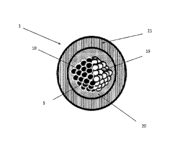
Figure 1 illustrates an embodiment of the microparticle (1). The microparticle
comprises a Janus
microparticle (5) suspended in a non-evaporating liquid (20) that is
encapsulated by a hard
polymer shell (25).
The Janus microparticle (5) comprises two portions (10, 15) that are
chemically or structurally
distinct. Each portion (10, 15) may be hemispherical, thereby leading to an
overall spherical
shape of the Janus microparticle (5). Alternatively, each portion (10, 15) can
be partly spherical,
thereby giving the Janus microparticle (5) the semblance of a dumbbell shape.
Other shapes and
configurations are possible, giving rise to (asymmetric) Janus microparticles
that can be used in
the microparticle (1).
In the embodiment shown in Fig. 1, each distinct portion (10, 15) comprises a
polymerized
assembly of particles. As an example, these particles can be selected from
pigments, dyes,
nanoparticles and any combination thereof In addition, the particles can be
transparent,
reflective, fluorescent, plasmonic, magnetic or electrically charged.
As an example, the first portion (10) of the Janus particle (5) can consist of
fluorescent silica
nanoparticles embedded in a polymer, while the second portion (15) can consist
of magnetic and
11
CA 02972113 2017-06-23
WO 2016/101079
PCT/CA2015/051373
plasmonic gold-coated silica-iron-oxide nanoparticles. As further sub-
examples, the first portion
(10) of can consist of polymerized Polyethylene (glycol) Diacrylate (PEG-DA)
loaded with
fluorescent silica nanoparticles, while the second portion (15) can consist of
polymerized PEG-
DA loaded with the plasmonic magnetic nanoparticles. Alternatively, the first
portion (10) of
can consist of polymerized ethoxylated trimethylolpropane triacrylate (EPTPA)
loaded with
fluorescent silica nanoparticles, while the second portion (15) can consist of
polymerized PEG-
DA loaded with the plasmonic magnetic nanoparticles. The fluorescent portion
of the Janus
microparticle (5) can be visible to the naked eye. This visual feature is
enhanced when there are a
multitude of such Janus microparticles (5).
The non-evaporating liquid (20) can be an aqueous solution, ionic liquid, oil,
lubricant or a resin.
The liquid can also contain surfactants and/or dispersion agents known in the
art that favor particle
dispersion and emulsion stabilization. In an example, the liquid and the
surfactant of the
microparticle can be selected from the perfluorinated polyether (PFPE) fluid
family.
The polymer shell (25) can be made of monomers that allow for dispersion of
the microparticle
(1) in aqueous solutions or solvents such that the microparticle (1) can be
directly printed on a
substrate of choice.
The overall size of microparticle (5) ranges from 1 nm to 1000 m.
Figures 2A ¨ 2C illustrate the response of the microparticle in Fig. 1 to an
external field.
Without an applied external field, as shown in Fig. 2A, the encapsulated Janus
microparticle (5)
is randomly oriented within the liquid (20) encapsulated by the shell (25).
However, in the
12
CA 02972113 2017-06-23
WO 2016/101079
PCT/CA2015/051373
presence of an external field (30) that acts on portion (10) and/or portion
(15), as shown in Fig.
2B, the suspended Janus microparticle (5) can be oriented within the liquid
(20) in the direction
of the applied external field. The external field can be magnetic, electric,
optical or gravitational.
Fig. 2C provides an example in which the external field is a magnetic field
provided by an
external magnet (35), and portion (15) comprises magnetic and plasmonic gold-
coated silica-
iron-oxide nanoparticles. The magnetic particles within portion (15) cause the
Janus
microparticle (5) to orient within the liquid (20) in the direction as shown.
Such an embodiment
can be used to make covert security features.
Figures 3A to 3C illustrate an example of an optical effect obtained by smart
ink printing on a
substrate. The smart ink comprises microparticles in which the first portion
comprises an
assembly of silica nanoparticles with florescence dye doping, while the second
portion comprises
an assembly of gold-coated-silica-shell-iron-oxide nanoparticles.
In Figure 3A, by applying a magnetic field during printing, microparticles are
oriented on the
surface of the substrate, and by subsequent selective UV exposure through a
mask pattern or by
laser writing, the aligned microparticles are permanently set in a polymerized
middle liquid. The
gold-coated nanoparticles in the Janus microparticle provide image color of a
design (40) (red
flower colors; in Fig. 3A, this is shown as a dark shaded portion of the
design (40)). The non-
exposed area of the printed image contains randomly oriented microparticles,
thus providing a
blurring effect of the (flower) design (40). Once printed, covert features are
seen when applying
a second magnetic field, revealing bright yellow features of the design (40)
(shown as the sharp
light-coloured outlines of the flower petals in Fig. 3B), which provide a
sharpened image.
13
CA 02972113 2017-06-23
WO 2016/101079
PCT/CA2015/051373
Finally, as an additional covert security feature, under UV light, the
particles fluoresce and/or
provide a specific plasmonic signature as illustrated in Figure 3C, where the
design (40) changes
in colour from the original red hue (or dark features in Fig. 3B) to a
fluorescent yellow (light
features shown in Fig. 3C).
An example of microparticle assembly with sharp and blurring fluorescence
effects without and
with the application of a magnetic field are shown in Figures 4A to 4D. Figs.
4A and 4C are
sample images of faint (or blurred) fluorescence without an external magnetic
field, where the
Janus microparticles are randomly oriented, and thus the fluorescence effects
are dampened due
to destructive interference. Figures 4B and 4D are sample images of intense
(or sharpened)
fluorescence in the presence of an external magnetic field. Here, the Janus
microparticles are no
longer randomly oriented, but rather, aligned with the external magnetic field
due to magnetic
nanoparticles in the Janus microparticle. The fluorescence effect is thus more
intense, as the
fluorescent portions of the Janus microparticles are aligned, rather than
randomly oriented.
Second embodiment
Figure 5 illustrates another embodiment of the microparticle (100), while
Figure 6 illustrates a
Janus particle (45) used in the embodiment of Figure 5.
As in the first embodiment shown in Figure 1, microparticle (100) comprises a
Janus
microparticle (45) suspended in a non-evaporating liquid (20) that is
encapsulated by a hard
polymer shell (25). The Janus microparticle (45), shown in greater detail in
Figure 6, can consist
of a homogeneous polymer core (50) that can be loaded with functional
nanoparticles (silica,
14
CA 02972113 2017-06-23
WO 2016/101079
PCT/CA2015/051373
fluorescent, plasmonic or composite thereof), dyes or colorants. While a
spherical core is shown
in Figure 6, it is understood that the polymer core (50) may take other
suitable shapes. The
surface of one hemisphere of the polymer core (50) is coated with a layer of
material acting as a
hemispherical shell (55) in order to impart a separate functionality. This can
be achieved using,
for example, deposited thin magnetic films or assembly of a monolayer of
magnetic
nanoparticles deposited using solvent evaporation and self-assembly. This
hemisphere can be
subsequently covered with an optically absorbing thin film (60) to provide
color contrast from
the uncoated hemisphere.
In particular, one advantage of Janus microparticles (45) having a hemisphere
coated with
electroless-deposited Nickel or an assembly of nanoparticles covered by thin
absorbing films
(60), is the retention of a low remnant magnetic moment in the Nickel layer
which enables
switchability of visual optical effect by applying and removing the magnetic
field without any
chain formation or agglomeration.
As examples of this embodiment, the polymer core (50) of the microparticle can
be composed of
a polymer loaded with fluorescent dye, nanoparticles or colorant or any
combination thereof. An
example of suitable polymers includes PEGDA, ETPTA, polystyrene, PMMA and
other
polymers known in the art. The assembly of nanoparticles (55) can consist, for
example, of
superparamagnetic nanoparticles such as iron-oxide nanoparticles or silica-
coated iron-oxide
nanoparticles. The absorbing thin film (60) can be a combination of dielectric
and metallic thin
films such as gold, chromium, nickel, titanium, silicon dioxide and silicon
nitride. In an
CA 02972113 2017-06-23
WO 2016/101079
PCT/CA2015/051373
embodiment, the absorbing thin film (60) can consist of sequential layers of:
chromium, gold,
nickel, chromium, silicon dioxide, chromium and silicon dioxide.
Figures 7A to 7C illustrate the response of a microparticle (100) shown in
Fig. 5 to an external
field. Without an applied external field, as shown in Fig. 7A, the
encapsulated Janus
microparticle (45) is randomly oriented within the liquid (20) encapsulated by
the shell (25).
However, as illustrated in Figure 7B, in the presence of an external field
(30), the suspended
Janus microparticle (45) can be oriented within the liquid (20) in the
direction of the applied
external field. The external field (30) can be magnetic, electric, optical or
gravitational. Fig. 7C
provides an example in which the external field is a magnetic field provided
by an external
magnet (35).
As with the first embodiment, an ink comprises a plurality of these
microparticles (100), which is
printed on a surface of a substrate. Without the presence of an external
field, the encapsulated
Janus microparticles are randomly oriented within the liquid encapsulated by
the shell. As such,
the collective optical effect of the printed microparticles is random.
However, by applying an
external field (for example, a permanent magnet), the suspended Janus
microparticles can be
oriented within the liquid in the direction of the applied field thus
exhibiting the desired optical
effect.
As an example, the magnetic manipulation of microparticles, each with an
encapsulated Janus
microparticle exhibiting one hemisphere that is fluorescent and a second
hemisphere that is
magnetic is demonstrated in Figure 8FIGS. 8A-B. The microparticle (150)
comprises a polymer
16
CA 02972113 2017-06-23
WO 2016/101079
PCT/CA2015/051373
shell (165), fluid (160) and the Janus microparticle (155). The fluid (160) is
a liquid monomer.
The Janus microparticle core is composed of PEGDA loaded with a fluorescent
dye. One
hemisphere of the microparticle is covered by magnetic and absorbing thin film
consisting of Ni
(30 nm) - Au (80 nm) ¨ Cr (2 nm) - SiO2 (80 nm) - Cr (10 nm) - SiO2 (80 nm).
The particle is
suspended in PFPE fluid (Galden HT 200 liquid) containing PFPE surfactant
(Krytox). The shell
consists of photopolymerized ETPTA. In Fig. 8A, there is an absence of an
applied magnetic field,
whereas in Fig. 8B, a magnetic field is turned on. In FIG. 8B, the Janus
microparticle (50) orients in
alignment with the applied magnetic field. This is seen by the light color of
the aligned Janus
microparticle (50) in FIG. 8B, compared to the dark color of the non-aligned
Janus microparticle
(50) in FIG. 8A.
Method of manufacture
The fabrication of microparticles can be achieved by use of microfluidic
technology in which a
microemulsion system is implemented. The microfluidic device can be fabricated
from, for
example, silicon, glass, PDMS, thermoplastic polymers such as COC, PMMA, PC,
PS or
thermoplastic elastomer using photolithography, wet or dry etching, soft-
lithography, hot-
embossing, nanoimprinting, injection-molding etc. An example of a microfluidic
system (200) is
shown in Figure 9. The microfluidic device (200) consists of three flow-
focusing junctions that
are used to generate microdroplets in microfluidic channels (explained in
greater detail in Fig.
10). The dimensions of the device can be 2cm by 5cm, although other dimensions
are possible.
By flowing aqueous solution as a dispersed phase and oil solution as a
continuous phase, water-
in-oil emulsions can be obtained. Similarly, by flowing oil solutions as a
dispersed phase and
17
CA 02972113 2017-06-23
WO 2016/101079
PCT/CA2015/051373
aqueous solutions as a continuous phase, oil-in-water emulsions can be
obtained. Therefore, by
connecting three junctions in parallel and alternating aqueous solutions
(monomers) and oil
solutions, a triple emulsion is generated. By changing the flow velocity of
continuous and
dispersed phases and the size of a given junction, various droplet sizes can
be obtained (for
example, from 1 to 1000 m).
The microfluidic device utilizes a flow focusing method to create triple
emulsion droplets, as
illustrated in Figure 10. For generation of Janus droplets of the first
embodiment, monomer A
(61) and monomer B (65) compositions are injected in the first two inlets (70,
75) respectively
and co-flow to a junction (80). As an example, monomer A can contain magnetic-
gold
nanoparticles while monomer B can contain fluorescent nanoparticles. The
junction is
intercepted perpendicularly by two channels (85, 90) that carry the non-
evaporating liquid (95)
(ionic liquid, oil or resin) which enables the creation of Janus droplets
(105) through flow-
focusing. The non-evaporating liquid (95) then carries the generated Janus
droplets (105) to a
second junction (110) which is intercepted by two channels (115, 120) flowing
monomer C
(125).
Alternatively, in the case of Janus particles of the second embodiment,
fabricated using
electroless Nickel deposition or self-assembled solvent evaporated magnetic
nanoparticles (see,
for example, Figures 11A and 11B), the particles are directly dispersed in the
non-evaporating
liquid (95) and injected into the second junction (110) illustrated in the
Figure 10, thereby
bypassing the first junction (80). After junction (110), a double emulsion
(130) composed of
Janus droplet encapsulated in the non-evaporating liquid surrounded by monomer
C continuous
phase is created. Finally, monomer C is flowed through a third junction (135)
and intercepted by
18
CA 02972113 2017-06-23
WO 2016/101079
PCT/CA2015/051373
two channels (140, 145) carrying the continuous oil (or aqueous) phase (150).
The resulting
triple-emulsion (155) is generated composed of a Janus droplet immersed in the
non-evaporating
liquid that is encapsulated in the monomer C surrounded by continuous oil
phase. A UV point
source (160) near the third junction is then used to expose and polymerize
monomers A, B and
.. C, resulting in a smart microparticle (165).
Alternatively, as illustrated in Figures 11A and 11B, the Janus microparticle
can be fabricated
starting with a homogeneous microparticle core (300), followed by deposition
of a thin film
(305) (as in Fig. 11A) or deposition of an assembly of nanoparticles (310)
over one hemisphere
of the microparticle core (300) (as in Fig. 11B).
The microparticle core (300) can be composed of a polymer loaded with
fluorescent dye,
nanoparticles or colorant or any combination thereof. An example of suitable
polymers includes
PEGDA, ETPTA, polystyrene, PMMA and others known in the art.
In Fig. 11A, a solution (315) of polymer microparticles dispersed in aqueous
solution or solvent
is deposited on a substrate (316) and solvent is evaporated. Upon solvent
evaporation,
microparticle cores create a densely packed monolayer of particles. The thin
film (305) is
subsequently deposited over the monolayer of microparticle cores. As
illustrated in Figure 11A,
electroless Nickel solution is added drop-wise to the substrate containing a
monolayer of
microparticle cores (300). The substrate resides on a hot plate which
initiates electroless Nickel
deposition (305) on the surface of the microparticle cores (300). Following
electroless Ni
deposition, the deposited Nickel is further coated with an absorbing coating
(320). The absorbing
19
CA 02972113 2017-06-23
WO 2016/101079
PCT/CA2015/051373
thin film (320) can be a combination of dielectric and metallic thin films
such as gold,
chromium, nickel, titanium, silicon dioxide and silicon nitride.
In an embodiment, the absorbing thin film (320) can consist of chromium, gold,
nickel,
chromium, silicon dioxide, chromium and silicon dioxide. For example, the
absorbing coating
can consist of Au (80 nm) ¨ Cr (2 nm) - SiO2 (80 nm) - Cr (10 nm) - SiO2 (80
nm) deposited using
sputtering or evaporation.
As illustrated in Fig. 11B, superparamagnetic functionality can be imparted to
the Janus
microparticle by deposition of superparamagnetic nanoparticles (310) on one
hemisphere of the
polymer microparticle core (300). The superparamagnetic nanoparticles (310)
can consist of
iron-oxide nanoparticles, silica-coated iron-oxide nanoparticles or gold-
silica iron-oxide
nanoparticles. As illustrated in Figure 11B, a solution (325) containing
superparamagnetic
nanoparticles (310) is added dropwise to the substrate (316) containing a
monolayer of
microparticle cores (300). Following evaporation of nanoparticle solution, a
monolayer of
superparamagnetic nanoparticles (310) is formed on one hemisphere of the
microparticle cores
(300). Subsequently, thin absorbing film (320) is deposited to ensure that
nanoparticles (310) are
embedded in the newly formed Janus particle. The absorbing thin film (320) can
be a
combination of dielectric and metallic thin films such as gold, chromium,
nickel, titanium,
.. silicon dioxide and silicon nitride.
In an embodiment, the absorbing thin film (320) can consist of chromium, gold,
nickel,
chromium, silicon dioxide, chromium and silicon dioxide. For example, the
absorbing coating
CA 02972113 2017-06-23
WO 2016/101079
PCT/CA2015/051373
can consist of Au (80 inn) ¨ Cr (2 nm) - SiO2 (80 rim) - Cr (10 rim) - SiO2
(80 rim) deposited using
sputtering or evaporation.
It will be appreciated by persons skilled in the art that the foregoing
disclosure constitutes a
description of specific embodiments of the microparticles, an ink comprising
the microparticles,
as well as, an apparatus and methods for producing the microparticles. These
embodiments are
only exemplary and are not meant to limit the disclosure to what has been
particularly shown and
described herein above. A variety of modifications and variations are possible
in light of the
above teachings without departing from the scope of the present disclosure.
The ink comprising
113 the microparticles, as well as, an apparatus and methods for producing
the microparticles are
further described and defined in the claims which now follow.
21