Note: Descriptions are shown in the official language in which they were submitted.
CA 02972146 2017-06-23
- 1 -
Joint-Sealing Tape Having Predetermined Geometry and Sealing Assembly
Having Such a Joint-Sealing Tape
FIELD OF THE INVENTION
The present invention relates to a joint-sealing tape as well as a sealing
arrangement with such joint-sealing tape for sealing of building structure
joints,
especially for sealing against sound and smoke and if applicable against fire.
In
particular, the invention relates to acoustic, smokeproof and/or fireproof
sealing of
connecting joints in drywalls, especially of expansion joints.
BACKGROUND OF THE INVENTION
Connecting joints are usually formed when different building parts meet.
Connecting
joints are found in the region of connection to the inter-story ceiling, to
the floor and
to massive walls. Due to weight loading or thermal influences, the ceiling in
buildings may be forced upward or downward. To prevent damage to the drywall,
the upper connecting joint in this case is made as an expansion joint. Thus
joints for
creating discontinuities in building parts in order to prevent stress cracking
are
known as expansion joints. The ceiling profile is made in such a way that a
relative
movement between ceiling profile and the vertical wall components is possible.
In general, a channel profile constituting part of the studwork is fastened to
the
connecting building parts. The gypsum boards themselves are attached at a well-
defined spacing to the connecting building part. Usually sealing of the system
is
provided in the gap between gypsum board and ceiling. For this purpose, either
a
suitable sealing compound is introduced or else the gap is filled with mineral
wool
and provided at the surface with a sealing layer. In both cases, the material
present
in the joint presents relatively strong resistance to movement, with the
consequence
CA 02972146 2017-06-23
. ,
- 2 -
that comparatively large joint widths are necessary in order to achieve
adequate
movement absorption.
In particular, sealing of the gap with sealing compound has some
disadvantages. It
is particularly laborious, and in the course of time the sealing tends to
crack when
overloaded. Furthermore, sealing can be performed only after the gypsum boards
have been mounted, and it requires access to the finished drywall from both
sides.
Furthermore, this procedure is error-prone, since the user himself or herself
must
dose the correct quantity of material in order to seal the gap adequately.
Above and
beyond this, the drywall builder must make the width of the joint correspond
to the
material and expansion properties of the sealing compound. During installation
of
the sealing compound, nothing but the joint can be filled. During expansion of
the
gap, it must be ensured that the sealing compound adheres sufficiently
strongly to
the underlying surface and that it is able to absorb the tensile forces that
develop.
Frequently this not the case, and the danger exists that the sealing compound
will
become detached from the underlying surface or that the sealing compound
itself
will be overloaded and tear. In the case of a narrower gap, the sealing
compound
can be compressed to only a limited extent, because of its material
properties, and
the danger exists that it will be forced out of the gap if the joint is
incorrectly
dimensioned. Due to the limited expansion and compression capability of the
sealing compound (max. +1- 25%), it is very important to ensure adequately
large
dimensioning of the spacing between gypsum board and ceiling. This is
frequently
underestimated, and so adequate imperviousness often cannot be guaranteed
during use of customary sealing compounds.
Some further approaches exist for sealing of joints, especially joint cords or
joint
sprays, which to some extent suffer from the same disadvantages as have been
described for sealing compounds.
The object of the present invention is therefore to provide a joint-sealing
tape that
avoids the disadvantages of the known materials, that in particular is easier
and
safer to use, simplifies the mounting of further building parts and ensures
good
sealing as soon as it is applied as well as excellent imperviousness with
maximum
absorption of movement.
- 3 -
A further object of the present invention is to provide an arrangement that,
in the
event of fire, permits better sealing of the joint between two building parts,
especially between a drywall and a connecting building part, such as a wall, a
ceiling or a floor, and thus provides better and durable sealing against sound
and/or smoke and if necessary better and durable fire protection, and can be
mounted reliably and free of defects with little work effort.
This and further objects that will become apparent from the description of the
invention hereinafter are solved by the present invention, as described
herein.
Preferred embodiments are also described herein.
SUMMARY OF THE INVENTION
The present invention relates to a joint-sealing tape for sealing a joint
between a
first building part and a second building part, with a sealing element and an
adhesive layer, which is characterized in that the sealing element has a
predetermined geometry.
The present invention further relates to a sealing arrangement for sealing a
joint
between two juxtaposed building parts of a building construction and/or of a
building structure with at least one first building part, one second building
part
and the joint-sealing tape described in the foregoing, wherein the sealing
element
is positioned in the upper region of the joint and is configured to seal the
joint
from the outside.
Accordingly, in one aspect of the invention there is provided a joint-sealing
tape
for sealing a joint between a first building part and a second building part,
said
joint-sealing tape comprising: a seal including foam, sponge rubber, or
cellular
rubber and having a profile which is a round or polygonal profile and which is
not
hollow, and an adhesive layer including a first side directly or indirectly
coupled to
a first area of the seal and a second side opposing the first side, the second
side
Date Recue/Date Received 2022-11-07
- 3a -
including an adhesive material for attachment to the first building part, the
adhesive layer unattached to a second area of the seal facing the second
building part so that the second building part is free to move relative to the
second area of the seal, wherein the seal has a predetermined geometry,
wherein the foam, sponge rubber, or cellular rubber is an intumescent
material,
wherein a length of the adhesive layer is less than or substantially equal to
a total
length of an outer surface of the seal, and wherein the adhesive layer extends
from the seal in a first direction with respect to a longitudinal axis of the
seal in an
uninstalled state and extends from the seal in a second direction with respect
to
the longitudinal axis of the seal in an installed state, the second direction
extending in a same direction as a surface of the first building part and
different
from the first direction.
In yet another aspect, the present invention provides a joint-sealing tape for
sealing a joint between a first building part and a second building part, said
joint-
sealing tape comprising: a seal including foam, sponge rubber, or cellular
rubber
and having a profile which is a round or polygonal profile and which is not
hollow,
and an adhesive layer including a first side directly or indirectly coupled to
a first
area of the seal and a second side opposing the first side, the second side
including an adhesive material for attachment to the first building part, the
adhesive layer unattached to a second area of the seal facing the second
building part so that the second building part is free to move relative to the
second area of the seal, wherein the seal has a predetermined geometry,
wherein the foam, sponge rubber, or cellular rubber is an intumescent
material,
wherein a length of the adhesive layer is less than or substantially equal to
a total
length of an outer surface of the seal, and wherein the adhesive layer and the
seal form a first angle in an uninstalled state and wherein the adhesive layer
and
the seal form a second angle in an installed state which is different from the
first
angle.
Date Recue/Date Received 2022-11-07
- 3b -
Some other objects and features of this invention are obvious and some will be
explained hereinafter. In particular, the subject matter of the present
invention will
be described in detail by reference to the following figures:
BRIEF DESCRIPTION OF THE FIGURES
Fig. la shows a sketched front view of a joint-sealing tape with a sealing
element
and an adhesive layer according to one embodiment of the present invention,
wherein the sealing element has a solid profile and round profile.
Date Recue/Date Received 2022-11-07
CA 02972146 2017-06-23
- 4 -
Fig. lb shows a cross section through the embodiment of an inventive joint-
sealing
tape shown in Fig. I a.
Fig. 1 c shows a perspective view of the embodiment of an inventive joint-
sealing
tape shown in Figs. la and lb.
Fig. Id shows a sketched sealing arrangement with the embodiment of an
inventive
joint-sealing tape shown in Figs. la to lc.
Fig. le shows a sectional view through a finished building element with the
embodiment of an inventive sealing arrangement shown in Fig. Id.
Fig. 2a shows a sketched front view of a joint-sealing tape with a sealing
element
and an adhesive layer according to one embodiment of the present invention,
wherein the sealing element has a solid profile and round profile and wherein
the
sealing element is provided with a projecting film.
Fig. 2b shows a cross section through the embodiment of an inventive joint-
sealing
tape shown in Fig. 2a.
Fig. 2c shows a sketched sealing arrangement with the embodiment of an
inventive
joint-sealing tape shown in Figs. 2a and 2b.
Fig. 2d shows a sectional view through a finished building element with the
embodiment of an inventive sealing arrangement shown in Fig. 2c.
Fig. 3a shows a sketched front view of a joint-sealing tape with a sealing
element
and an adhesive layer according to one embodiment of the present invention,
wherein the sealing element has a solid profile and rectangular profile.
Fig. 3b shows a cross section through the embodiment of an inventive joint-
sealing
tape shown in Fig. 3a.
CA 02972146 2017-06-23
- 5 -
Fig. 3c shows a perspective view of the embodiment of an inventive joint-
sealing
tape shown in Figs. 3a and 3b.
Fig. 3d shows a sketched sealing arrangement with the embodiment of an
inventive
joint-sealing tape shown in Figs. 3a to 3c.
Fig. 3e shows a sectional view through a finished building element with the
embodiment of an inventive sealing arrangement shown in Fig. 3d.
Fig. 4a shows a sketched front view of a joint-sealing tape with a sealing
element
and an adhesive layer according to one embodiment of the present invention,
wherein the sealing element has an open hollow profile and round profile.
Fig. 4b shows a cross section through the embodiment of an inventive joint-
sealing
tape shown in Fig. 4a.
Fig. 4c shows a sketched sealing arrangement with the embodiment of an
inventive
joint-sealing tape shown in Figs. 4a and 4b.
Fig. 4d shows a sectional view through a finished building element with the
embodiment of an inventive sealing arrangement shown in Fig. 4c.
Fig. 5a shows a sketched front view of a joint-sealing tape with a sealing
element
and an adhesive layer according to one embodiment of the present invention,
wherein the sealing element has a closed hollow profile and rectangular
profile.
Fig. 5b shows a cross section through the embodiment of an inventive joint-
sealing
tape shown in Fig. 5a,
Fig. 5c shows a sketched sealing arrangement with the embodiment of an
inventive
joint-sealing tape shown in Figs. 5a and 5.
Fig. 5d shows a sectional view through a finished building element with the
embodiment of an inventive sealing arrangement shown in Fig. 5c.
CA 02972146 2017-06-23
- 6 -
Fig. 6 shows the stepwise procedure for manufacturing a finished building
element
by means of the embodiment of an inventive joint-sealing tape shown in Figs.
1a to
1 C.
DETAILED DESCRIPTION OF THE INVENTION
The following terms are used within the scope of the present invention:
Within the scope of the present invention, the term "geometry / geometries"
comprises various cross-section types and cross-section shapes. This means
that
the sealing element may have different cross-section types and cross-section
shapes. Cross-section types are understood among other possibilities as round
profile (round cross section), polygonal profile (polygonal cross section),
especially
square profile (square cross section), rectangular profile (rectangular cross
section),
parallelogram profile (cross section in the shape of a parallelogram), etc.
Cross-
sectional shapes are understood among other possibilities as solid profile and
hollow profile, wherein solid profile means that the sealing element consists
completely of sealing material while the hollow profile means that the sealing
element consists only partly of sealing material.
Within the scope of the present invention, the term "deformable" means that
irregularities in the building part, against which the sealing element is
pressed, can
be evened out. In this connection, "plastically deformable" means that the
sealing
element is deformable and no longer returns to its original shape after
deformation.
Analogously, "elastically deformable" means that the sealing element is
deformable
and returns to its original shape after deformation, i.e. the material can be
deformed
reversibly to a certain extent.
The terms "exhibit", "with" and "have" are intended to be inclusive and mean
that
elements other than those cited may also be meant.
CA 02972146 2017-06-23
- 7 -
Within the scope of the present invention, the term "intumescence" means that,
under the effect of heat, for example in the event of a fire, the material
swells and
forms an insulating layer of flame-retardant material, i.e. intumesces.
Within the scope of the present invention, "slow-burning foam" is understood
as a
foam that offers no possibility of fire propagation due to the foam, is not
spontaneously flammable and also does not drip.
"Positioned in the upper region of the joint" means that this joint sealing
tape is
disposed in particular on the second building part, preferably a ceiling.
Within the scope of the present invention, the term "adhesive layer" means in
particular a self-adhesive layer, but it may also be present in the form of
interlocking
or frictionally acting means, such as suitable profiled shapes or putty
material, or
may be produced by means of a separately applicable adhesive or the like.
As used within the scope of the present invention, the singular forms "one",
"a" and
"an" also include the corresponding plural forms, unless something different
can be
inferred unambiguously from the relationship. Thus, for example, the term
"one" is
intended to mean "one or more" or "at least one", unless otherwise indicated.
In one aspect, the present invention relates to a joint-sealing tape for
sealing a joint
between a first building part and a second building part, with a sealing
element and
an adhesive layer, characterized in that the sealing element has a
predetermined
geometry.
In a further aspect, the present invention relates to a sealing arrangement
for
sealing a joint between two juxtaposed building parts, with at least one first
building
part, one second building part and the joint-sealing tape described in the
foregoing,
wherein the joint-sealing tape is positioned in the upper region of the joint
and is
configured to seal the joint from the outside.
It has been discovered that the inventive joint-sealing tape is particularly
suitable for
safely sealing, in simple manner, a building-structure joint between two
adjacent
CA 02972146 2017-06-23
- 8 -
building parts, especially against sound and/or smoke and if necessary also
against
fire. For the joint-sealing tape to be able to fulfill its function, the
sealing element of
the joint-sealing tape must have a predetermined geometry. Furthermore, the
joint-
sealing tape must be positioned in the upper region of the joint and be
configured
such that it can seal the joint from the outside.
Therefore it is an objective of the present invention to describe the sealing
element.
In particular, it is an objective of the present invention to describe the
geometry of
the sealing element in detail. Furthermore, it is an objective of the present
invention
to describe the positioning of the joint-sealing tape, especially a sealing
arrangement.
The inventive joint-sealing tape for sealing a joint between a first building
part and a
second building part, with a sealing element and an adhesive layer, is
characterized
in that the sealing element has a predetermined geometry. As already mentioned
hereinabove, geometries within the scope of the present invention comprise
various
cross-section types and cross-section shapes.
Preferred cross-section types of the sealing element according to the present
invention are solid profiles, wherein the hollow profile may be a closed or
open
hollow profile. Solid profiles and hollow profiles with large profile wall
thicknesses
have the advantage that automatically no gaps develop at the abutting surface
between sealing elements in contact with one another. Hollow profiles can be
compressed to a greater extent and thus absorb more movement. Particularly
preferably, the sealing element has a solid profile.
Preferred cross-section shapes of the sealing element according to the present
invention are round profile, polygonal profile, especially rectangular
profile, square
profile, parallelogram profile and triangular profile. Round profile and
rectangular
profile are particularly preferred, but rectangular profile is the most
preferred.
Nevertheless, other or mixed cross-section shapes are also conceivable and
possible, as long as the joint-sealing tape adjoins both building parts after
installation of the sealing element and is able to close the joint that is
present
between the building parts.
CA 02972146 2017-06-23
- 9 -
In a preferred embodiment of the inventive joint-sealing tape, the sealing
element
has a round profile.
In a further preferred embodiment of the inventive joint-sealing tape, the
sealing
element has a rectangular profile.
In a particularly preferred embodiment of the inventive joint-sealing tape,
the sealing
element has a solid profile and a round profile.
In a further particularly preferred embodiment of the inventive joint-sealing
tape, the
sealing element has a solid profile and a rectangular profile.
The geometry of the sealing elements may be prefabricated, for example by well-
defined cutting to size, extrusion or pressing of suitable sealing material or
can be
manufactured directly from flat material, for example by means of folding or
rolling
from a flat starting material, for example from fabric, especially from an
incombustible material, such as inorganic fibers, for example glass fibers, a
nonwoven fabric or the like. The manufacture of such cross-section types and
cross-
section shapes is known to the person skilled in the art. Preferably the
geometry of
the sealing element is prefabricated by well-defined cutting to size or
extrusion.
The inventive sealing element may consist of one piece made from one material
or
of multiple parts made from several materials and, for example, may exist as a
layered body. In alternative embodiments, the outer region and the inner
region of a
sealing element may define separate regions of the sealing element, which may
have different cross-section shapes and/or cross-section types and/or may
consist
of different materials.
According to the invention, the sealing element consists of a deformable
material.
This material may be either plastically or elastically deformable. In
particular, the
sealing element consists at least partly, preferably completely of a material
that is
resilient after compression, such as foam, sponge rubber, cellular rubber or
the like.
The inventive sealing element preferably consists of a soft foam that is
resilient after
compression. Common foams such as polyethylene and polyurethane foams or
CA 02972146 2017-06-23
- 10 -
cellular rubber can be mentioned as foam material. This foam may be an open-
celled foam with very low air passage resistance, or else an approximately
closed-
celled foam with extremely low air permeability values. Even foams with air
permeability values lying between the two extreme cases mentioned in the
foregoing may be used within the scope of the present invention. The foam may
be
impregnated with an impregnating agent that increases the sealing properties
of the
foam. In order to achieve imperviousness to smoke, at least the outer surface
of the
sealing element must be of closed-pore nature. Alternatively, an open-celled
sealing
element may be provided with a covering layer or jacket, for example of a
film,
especially plastic film. Preferably, the sealing element consists of an open-
celled
polyurethane foam or of a cellular rubber.
It has proved advantageous when the sealing element consists of a slow-burning
foam, such a cellular rubber or polyurethane foam, for example. In the case of
a
slow-burning foam, there is no possibility that fire will be propagated by the
foam.
Spontaneous inflammation is ruled out by the above-mentioned foam-type
starting
materials. It is also advantageous that no dripping occurs in the event of
fire. A slow-
burning foam should still have at least 20%, still at least 25%, preferably
still at least
30%, between 20% and 60%, between 20% and 40%, preferably between 25% and
30% of its initial volume in a temperature range between 500 C and 800 C.
Furthermore, a slow-burning foam should still have at least 10%, at least 20%,
preferably still at least 30%, between 10% and 40%, between 10% and 30%,
preferably between 15% and 20% of its initial mass in a temperature range
between
500 C and 800 C.
Furthermore, the material may contain appropriate additives if fire protection
properties such as intumescence, for example, are desired. Under the effect of
heat,
such as in the event of fire, the material swells and forms an insulating
layer of
flame-retardant material. The formation of a voluminous insulating layer,
namely an
ash layer, may take place due to the chemical reaction of a mixture of
compounds
that are appropriately matched to one another and that react with one another
under
the effect of heat. Such systems are known to the person skilled in the art as
chemical intumescence, and they may be used according to the invention.
Alternatively, the voluminous insulating layer may be formed by swelling of an
CA 02972146 2017-06-23
- 1 1 -
individual compound, which releases gases under the effect of heat, even
though no
chemical reaction has occurred between two compounds. Such systems are known
to the person skilled in the art as physical intumescence, and they may also
be used
according to the invention. According to the invention, the two systems may be
used
respectively alone or together as a combination.
In a preferred embodiment of the inventive joint-sealing tape, the sealing
element
consists of an open-celled foam.
In a further preferred embodiment of the inventive joint-sealing tape, the
sealing
element consists of a closed-celled foam.
In a particularly preferred embodiment of the inventive joint-sealing tape,
the sealing
element consists of an open-celled polyurethane foam.
In a further particularly preferred embodiment of the inventive joint-sealing
tape, the
sealing element consists of a cellular rubber.
In one embodiment of the inventive joint-sealing tape, the sealing element is
firmly
surrounded at least over part of its circumference by a covering layer or
jacket, for
example of a film, especially plastic film.
In a further embodiment of the inventive joint-sealing tape, the sealing
element is
firmly surrounded over its entire circumference by a covering layer or jacket,
for
example of a film, especially plastic film. Thus an open-celled foam material
may be
used for the sealing element.
For manufacturing reasons, it may be advantageous to provide the sealing
element
with a projecting film, such as a film strip.
The adhesive layer of the inventive joint-sealing tape may be produced in the
form
of an adhesive layer, especially a self-adhesive layer, in the form of
interlocking or
frictionally acting means, such as suitable profiled shapes or putty material
or by
means of a separately applicable adhesive or the like. Synthetic adhesives
such as
CA 02972146 2017-06-23
, . - 12 -
acrylate adhesives or hot-melt adhesives may be used in the present invention,
although silicone-base adhesives are also conceivable. Preferably the adhesive
layer of the joint-sealing tape is a self-adhesive layer.
Positioning of the joint-sealing tape on the building part may also be
achieved by
fastening means, for example in the form of the just-mentioned adhesive layer,
especially a self-adhesive layer, in the form of interlocking or frictionally
acting
means, such as suitable profiled shapes or putty material, by means of a
separately
applicable adhesive or the like. Preferably the joint-sealing tape is
positioned on the
connecting building part by means of a self-adhesive layer.
Attachment, especially adhesive bonding, of the inventive joint-sealing tape
may be
achieved over an area or only at spots, preferably by pressing it on.
Specifically,
adhesive bonding is necessary only for temporary fixation of the joint-sealing
tape.
As soon as the gypsum board has been mounted, the joint-sealing tape is held
in
place by the precompression.
If the sealing element is provided with a projecting film, the adhesive layer
is applied
on the projecting film strip, which is bent over and then the joint-sealing
tape is
applied on the building part.
The dimension and the materials of the joint-sealing tape are chosen to
correspond
to the planned use of the joint-sealing tape.
In general, the dimension of the joint-sealing tape is chosen as a function of
the
profiles being used and of the material being used. The dimension must be
chosen
such that the joint-sealing tape fills the gap between the gypsum board and
the
ceiling and bears sealingly both on the ceiling and on the gypsum board. If a
vertical
movement of the gypsum boards is to be permitted, the joint-sealing tape must
follow the movement of the gypsum board, so that the contact with the gypsum
board is not torn apart and no gaps are able to form between joint-sealing
tape and
gypsum board. For this purpose, the sealing element of the joint-sealing tape
preferably consists of resilient and compressible material and is
appropriately
precompressed during mounting of the gypsum board, so that a downward
CA 02972146 2017-06-23
- 13 -
movement of the gypsum board, whereby the gap between this and the ceiling
becomes larger, can be followed. In this way, the preadjusted freedom of
movement
of the gypsum board determines the dimension of the sealing element and thus
of
the joint-sealing tape.
As an example, it must be pointed out that the height of the narrow side of a
rectangular sealing element will be chosen as a function of the desired use of
the
joint-sealing tape, in which case the height for a single-boarded arrangement
will be
chosen as approximately the thickness of one gypsum board and the height for a
double-boarded arrangement will be chosen as approximately twice the thickness
of
one gypsum board. In the case of a single-boarded arrangement, however, it is
also
possible to use the joint-sealing tape designed for a double-boarded
arrangement.
As an example, it must also be pointed out that material and geometry of the
sealing
element may be chosen in such a way that its hardness or compressibility is
adjusted such that the sealing element is compressed to a well-defined height
merely by the dead weight of the gypsum board in the floor region, for example
by
constructing the sealing element as two layers of foam materials with
different
compression density. In this way a correct spacing between floor and gypsum
board
can be adjusted without further measurement. This is necessary in particular
whenever damage to the gypsum board by rising dampness must be prevented.
The invention will be described in more detail hereinafter on the basis of the
application of the joint-sealing tape on a channel profile of a drywall
studwork,
without hereby restricting the scope of protection.
To create an inventive sealing arrangement, the inventive joint-sealing tape,
after
attachment of a first building part, is positioned on a second building part,
especially
abuttingly with the first building part. Preferably, the first building part
is a frame
profile of a drywall studwork, for example a channel profile, and the second
building
part is a wall, a ceiling or a floor of a building structure. Particularly
preferably, the
first building part is a channel profile and the second building part is a
ceiling. In this
arrangement, the joint-sealing tape is positioned in the upper region of the
joint and
is configured to seal the joint from the outside.
CA 02972146 2017-06-23
- 14 -
In one possibility for sealing a connecting joint in dry construction, after a
profile,
especially a channel profile, has been attached to the connecting building
parts,
such as a ceiling, wall or floor, the inventive joint-sealing tape is
positioned on or in
front of that channel profile and fixed on the connecting building part,
preferably a
ceiling. In a further operation, the gypsum boards, whether they have one or
two
layers, are pressed at the end face against the sealing element, so that, in
the case
of a double-boarded arrangement, the two gypsum boards come into contact via
respectively their top edge with the sealing element, especially with the
sealing strip,
and thereby sealing of the joint is achieved. In order to permit movement of
the
gypsum boards without the formation of a gap between the sealing element and
the
gypsum board or the gypsum board(s) in the case of maximum movement, the
sealing element must be compressed during mounting of the gypsum board(s). As
soon as the gypsum board has been mounted, the joint-sealing tape is held in
place
by the precompression, Furthermore, any irregularities that were present are
closed
by this compression.
For this purpose, the material and the thickness of the sealing element are
respectively chosen such that the sealing element does not hinder the movement
of
the gypsum board(s) and, at maximum joint width, the top edge of the gypsum
board(s) still remains in contact with the sealing element, in order to ensure
adequate sealing against gases. The width of the sealing element is preferably
chosen such that it corresponds approximately to twice the width of one gypsum
board. It has been found that sufficient sealing may also be achieved when the
width of the sealing element corresponds to the width of only one gypsum
board.
When the joint-sealing tape is disposed on the ceiling and abutted with the
channel
profile, irregularities in both building parts can be evened out and simple
positioning
with adhesive bonding on only one building part is possible. Furthermore, the
joint
spacing can be controlled by the subsequent positioning of the gypsum board as
well as by the choice of sealing materials and/or geometric configuration of
the joint-
sealing tape.
CA 02972146 2017-06-23
- 15 -
Alternatively, when only one gypsum board is used, it may be mounted not from
underneath in a manner abutting the sealing element, but instead in such a way
that
the gypsum board partly overlaps the sealing element. Thereby the gypsum board
partly overlaps the sealing element, and the overlapping part of the sealing
element
is pressed between the channel profile and the gypsum board. It has been found
that sufficient sealing can also be achieved hereby, especially against gases.
To
improve the imperviousness and/or the sliding properties, the sealing tape may
be
partly laminated with a layer of material, such as a plastic film, for
example, that
neither hinders the movement of the gypsum board nor is destroyed by it. As an
example, the positioning marking for the gypsum board may be easily applied on
a
film.
In this type of mounting, a large capacity for absorbing movement relative to
the
joint width is possible. Furthermore, this type is more mounting-friendly than
the
aforementioned single-boarded or double-boarded arrangement, since the gypsum
board can be mounted simply on the sealing element without the need to measure
the spacing. If positioning marking is used, the gypsum board can be mounted
without measurement of the spacing. Above and beyond this, there is no need to
use readily compressible materials for the sealing elements in this type of
mounting,
thus permitting relatively broad discretion in the choice of material.
In a further particularly preferred alternative, sealing of the joint can be
achieved
when, in the case of a double-boarded arrangement, the two gypsum boards are
mounted with a horizontal offset in such a way that the outer of the two
gypsum
boards (also referred to as the outer, second gypsum board) is mounted higher
(i.e.
closer to the ceiling) than the inner gypsum board (also referred to as the
inner, first
gypsum board). In this embodiment, the thickness of the sealing element is
chosen
to correspond to the thickness of one gypsum board. The first, inner gypsum
board
is mounted in such a way that its top edge contacts the end faces of the
sealing
element, in which case zero or little precompression of the sealing element is
necessary. The second, outer gypsum board is attached at a horizontal offset,
i.e. it
is mounted higher than the first, inner gypsum board, so that it partly
overlaps the
sealing strips. In this case the sealing element and the gypsum board should
bear
sealingly on one another, in order to seal the gap between the outer, second
CA 02972146 2017-06-23
- 16 -
gypsum board and the sealing element, especially against gases. Thus sealing
is
achieved between sealing element and the second building part, such as a
ceiling, a
wall or a floor, as well as between sealing element and outer, second gypsum
board.
An empty gap remains between the second building part, such as a ceiling, a
wall or
a floor, and the outer, second gypsum board. In the case of a vertical
movement of
the second building part or of the gypsum boards, this gap is completely
available to
absorb movement.
Depending on how far the outer, second gypsum board overlaps the sealing
element (size of the offset), a movement in the other direction may also be
absorbed. In this case, it is important that an overlap is still ensured
between the
second gypsum board and the sealing strip. Preferably, therefore, the
dimension of
the sealing element is chosen such that its thickness is somewhat larger than
the
thickness of one gypsum board and its height comprises somewhat more than the
maximum permissible movement of the building parts (maximum joint width).
By the fact that the thickness of the sealing element is larger than the
thickness of
the gypsum board, the gypsum board is pushed against the sealing element and
somewhat compressed while it is being mounted, whereby the gap between sealing
element and gypsum board is reliably sealed, especially against gases.
For easier adjustment of the correct joint dimension in the outer, second
gypsum
board, markings referred to as positioning marking may be made laterally on
the
joint-sealing tape. To improve the imperviousness and/or the sliding
properties, the
sealing tape may be laminated on one side with a layer of material, such as a
plastic
film, for example, that neither hinders the movement of the gypsum board nor
is
destroyed by it. As an example, the positioning marking for the outer, second
gypsum board may be easily applied on a film.
In this type of mounting, maximum absorption of movement relative to the joint
width
is possible. Furthermore, this type is very mounting-friendly, since firstly
the first
gypsum board can be mounted simply on contact with the sealing element without
CA 02972146 2017-06-23
- 17 -
the need to measure the spacing, Secondly, especially if positioning marking
is
used, the second gypsum board can also be mounted without measurement of the
spacing. Above and beyond this, the broadest possible discretion in the choice
of
material for the sealing elements is achieved by this type of mounting, since
these
are compressed only slightly and thus only slight requirements are imposed on
the
compressibility of the sealing element.
According to the invention, the joint-sealing tape can be applied on all kinds
of
connecting joints in which one building part meets another building part.
Accordingly, the joint-sealing tape may be used on all profiles, even closed
profiles
or wooden beams, which must be sealed to a connecting face.
A particularly preferred use of the joint-sealing tape relates to the sealing
of profiles
in dry construction, wherein the first building part is a ceiling, floor or
wall profile or a
metal or wood studwork of a dry construction element, and the second building
part
is a floor, a ceiling or a wall of a building element, for example a masonry
structure
or concrete building element. The profile may be any of the profiles commonly
used
for dry construction, regardless of whether it has a slotted or non-slotted
web or
slotted or non-slotted flange. The further building parts are gypsum boards,
which
bear closely on the profiles and are fastened to the studwork. In order to
permit
vertical movement of the gypsum boards, for example in the event of an
earthquake,
the gypsum boards are mounted to be vertically movable at a spacing from a
wall, a
floor or a ceiling. Thereby a space (also referred to as joint herein) is
formed
between the gypsum board and the wall, the floor or the ceiling. This joint is
filled by
the sealing element of the joint-sealing tape, so that the sealing element
seals the
joint against sound and/or smoke and, depending on material of the sealing
element, also against fire if necessary.
Without restricting the scope of protection of the invention, the invention
will be
described in more detail on the basis of special embodiments of the joint-
sealing
tape as well as its positioning. In these embodiments, the joint-sealing tape
is
applied to the connecting joints in drywalls. It is clear to the person
skilled in the art
that the sealing tape may also be applied to building-structure joints of
other types.
CA 02972146 2017-06-23
- 18 -
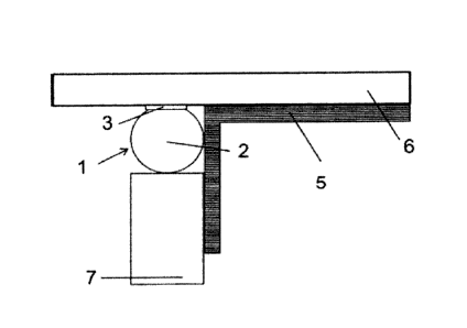
A preferred embodiment of an inventive joint-sealing tape 1 is shown in Figs.
la to
1 c. Joint-sealing tape 1 comprises a sealing element 2 and an adhesive layer
3.
Sealing element 2 has a round profile and a solid profile. Furthermore,
sealing
element 2 is surrounded completely, i.e. over its entire circumference, by a
covering
layer 4. Sealing element 2 consists of a compressible foam, which if necessary
contains fire-protection additives, and covering layer 4 consists of a plastic
film. Fig.
Id illustrates a sealing arrangement with the embodiment of an inventive joint-
sealing tape shown in Figs. 1 a to 1 c, wherein joint-sealing tape 1, after
attachment
of a channel profile 5, is positioned on a ceiling 6 and abuttingly with
channel profile
and is fixed on ceiling 6. Fig, le shows a sectional view through a finished
building
element with the embodiment of an inventive sealing arrangement shown in Fig.
Id,
wherein the sealing element is positioned in the upper region of the joint and
is
configured to seal the joint from the outside. In particular, the stepwise
procedure for
manufacturing a finished building element by means of the embodiment of an
inventive joint-sealing tape shown in Figs. 1 a to 1 c, for sealing a gap
between a
ceiling 6, channel profile 5 of a drywall studwork and a gypsum board 7, is
sketched
in Fig. 6.
A further preferred embodiment of an inventive joint-sealing tape 1 is shown
in Figs.
2a and 2b. Joint-sealing tape 1 comprises a sealing element 2 and an adhesive
layer 3. Sealing element 2 has a round profile and a solid profile.
Furthermore,
sealing element 2 is surrounded completely, i.e. over its entire
circumference, by a
covering layer 4. Furthermore, sealing element 2 is provided with a projecting
film
strip 4a. Sealing element 2 consists of a compressible foam, which if
necessary
contains fire-protection additives, and covering layer 4 as well as film strip
4a
consists of a plastic film. Fig. 2c illustrates a sealing arrangement with the
embodiment of an inventive joint-sealing tape shown in Figs. 2a and 2b,
wherein
joint-sealing tape 1, after attachment of a channel profile 5, is positioned
on a ceiling
6 and abuttingly with channel profile 5 and is fixed on ceiling 6. In this
embodiment,
adhesive layer 3 is applied on projecting film strip 4a, which is bent over
and then
the joint-sealing tape is applied on the building part. Fig. 2d shows a
sectional view
through a finished building element with the embodiment of an inventive
sealing
arrangement shown in Fig. 2c, wherein the sealing element is positioned in the
upper region of the joint and is configured to seal the joint from the
outside.
CA 02972146 2017-06-23
- 19 -
A further preferred embodiment of an inventive joint-sealing tape 1 is shown
in Figs.
3a to 3c. Joint-sealing tape 1 comprises a sealing element 2 and an adhesive
layer
3. Sealing element 2 has a rectangular profile and a solid profile. Sealing
element 2
consists of a compressible foam, which if necessary contains fire-protection
additives. Fig. 3d illustrates a sealing arrangement with the embodiment of an
inventive joint-sealing tape shown in Figs. 3a to 3c, wherein joint-sealing
tape 1,
after attachment of a channel profile 5, is positioned on a ceiling 6 and
abuttingly
with channel profile 5 and is fixed on ceiling 6. Fig. 3e shows a sectional
view
through a finished building element with the embodiment of an inventive
sealing
arrangement shown in Fig. 3d, wherein the sealing element is positioned in the
upper region of the joint and is configured to seal the joint from the
outside.
A further preferred embodiment of an inventive joint-sealing tape us shown in
Figs.
4a and 4b. Joint-sealing tape 1 comprises a sealing element 2 and an adhesive
layer 3. Sealing element 2 has an open hollow profile and a round profile.
Sealing
element 2 consists of a compressible foam, which if necessary contains fire-
protection additives. Fig. 4c illustrates a sealing arrangement with the
embodiment
of an inventive joint-sealing tape shown in Figs. 4a and 4b, wherein joint-
sealing
tape 1, after attachment of a channel profile 5, is positioned on a ceiling 6
and
abuttingly with channel profile 5 and is fixed on ceiling 6. The open side of
the
hollow profile of sealing element 2 points in the direction of channel profile
5. Fig. 4d
shows a sectional view through a finished building element with the embodiment
of
an inventive sealing arrangement shown in Fig. 4c, wherein the sealing element
is
positioned in the upper region of the joint and is configured to seal the
joint from the
outside.
A further preferred embodiment of an inventive joint-sealing tape us shown in
Figs.
5a and 5b. Joint-sealing tape 1 comprises a sealing element 2 and an adhesive
layer 3. Sealing element 2 has a closed hollow profile and a rectangular
profile.
Sealing element 2 consists of a compressible foam, which if necessary contains
fire-
protection additives. Fig. 5c illustrates a sealing arrangement with the
embodiment
of an inventive joint-sealing tape shown in Figs. 5a and 5b, wherein joint-
sealing
tape 1, after attachment of a channel profile 5, is positioned on a ceiling 6
and
CA 02972146 2017-06-23
- 20 -
abuttingly with channel profile 5 and is fixed on ceiling 6. Fig. 5c1 shows a
sectional
view through a finished building element with the embodiment of an inventive
sealing arrangement shown in Fig. Sc, wherein the sealing element is
positioned in
the upper region of the joint and is configured to seal the joint from the
outside.
The stepwise procedure for manufacturing a finished building element by means
of
the embodiment of an inventive joint-sealing tape shown in Figs. 1a to 1c, for
sealing a gap between a ceiling 6, channel profile 5 of a drywall studwork and
a
gypsum board 7, is sketched in Fig. 6. Firstly, in a first step I, joint-
sealing tape 1,
after attachment of a channel profile 5, is positioned on a ceiling 6 and
abuttingly
with channel profile 5 and is fixed on ceiling 6 in the usual way, preferably
by means
of adhesive layer. Then, in a second step II, gypsum board 7 is applied on the
flange of channel profile 5 and pushed upward in the direction of ceiling 6,
whereupon a gap remains between the top edge of gypsum board 7 and ceiling 6,
which is filled with sealing element 2 of joint-sealing tape 1, in order to
permit
vertical movement, for example, of gypsum board 7. Thereby sealing element 2
is
compressed and in this way seals the gap between ceiling 6 and channel profile
5
as well as the gap between ceiling 6 and gypsum board 7. The finished
structure is
shown in Fig. le.
Fig. 6 represents an example of the procedure for manufacturing a finished
building
element with joint-sealing tapes according to the present invention. Each
inventive
joint-sealing tape may be used in this way for sealing.
As is obvious from the foregoing explanations, the inventive joint-sealing
tape is
particularly suitable for safely sealing a building-structure joint between
two adjacent
building parts in simple manner, especially against sound and/or smoke and if
necessary also against fire.
Furthermore, application is very mounting-friendly, since no additional
fastening of
the joint-sealing element, for example to the profile or to a further
connecting
building part, such as a gypsum board, is necessary. Mounting is therefore
conceivably easy, and the working effort for mounting the joint-sealing tape
is
greatly reduced. The invention therefore achieves safe and reliable sealing of
joints
CA 02972146 2017-06-23
- 21 -
between two building parts, especially between a profile of a drywall studwork
and a
building part adjacent thereto, such as, for example, a ceiling, wall or
floor. In this
connection, two-sided sealing can be achieved in only one operation, by
providing a
prefabricated joint-sealing tape.
Furthermore, it has been shown that outstanding imperviousness can be achieved
with the inventive joint-sealing tape, since good compressibility of the
sealing
element is ensured without additional auxiliary means by the choice of the
sealing
materials and/or geometric configuration. By appropriate choice of the sealing
materials and/or geometric configuration, the invention also makes it possible
to
adjust the correct spacing from the connecting building part to the gypsum
board
without additional auxiliary means, in order to achieve the said
precompression.
By means of the inventive joint-sealing tape it is also possible to ensure
that, merely
by the choice of the sealing materials and/or geometric configuration,
sufficient
material is installed to ensure excellent imperviousness with maximum
absorption of
movement.
Furthermore, with the inventive joint-sealing tape, irregularities of the
surface of a
building part can be safely sealed as soon as one building part is disposed on
another building part, since the sealing element of the joint-sealing tape is
pressed
sufficiently firmly against the surface of the one building part and at the
same time
against the side faces of the other building part.
In view of the foregoing, it is obvious that the objects of the invention have
been
solved. Since various modifications can be made to the sealing element
described
hereinabove, without departing from the scope of the invention, it is intended
that all
subject matters contained in the foregoing description be interpreted as
illustrative
and not in a restrictive sense.