Language selection

Search

Patent 2972291 Summary

Third-party information liability

Some of the information on this Web page has been provided by external sources. The Government of Canada is not responsible for the accuracy, reliability or currency of the information supplied by external sources. Users wishing to rely upon this information should consult directly with the source of the information. Content provided by external sources is not subject to official languages, privacy and accessibility requirements.

Claims and Abstract availability

Any discrepancies in the text and image of the Claims and Abstract are due to differing posting times. Text of the Claims and Abstract are posted:

  • At the time the application is open to public inspection;
  • At the time of issue of the patent (grant).
(12) Patent Application: (11) CA 2972291
(54) English Title: AIR SUPPLY APPARATUS FOR AIR MATTRESS
(54) French Title: APPAREIL D'APPROVISIONNEMENT D'AIR DESTINE A UN MATELAS A AIR
Status: Dead
Bibliographic Data
(51) International Patent Classification (IPC):
  • A47C 27/10 (2006.01)
  • A47C 21/00 (2006.01)
(72) Inventors :
  • HUANG-CHI-CHUNG (Taiwan, Province of China)
(73) Owners :
  • APEX HEALTH CARE MFG. INC. (China)
(71) Applicants :
  • APEX HEALTH CARE MFG. INC. (China)
(74) Agent: ADE & COMPANY INC.
(74) Associate agent:
(45) Issued:
(22) Filed Date: 2017-06-30
(41) Open to Public Inspection: 2018-12-30
Examination requested: 2017-06-30
Availability of licence: N/A
(25) Language of filing: English

Patent Cooperation Treaty (PCT): No

(30) Application Priority Data: None

Abstracts

English Abstract


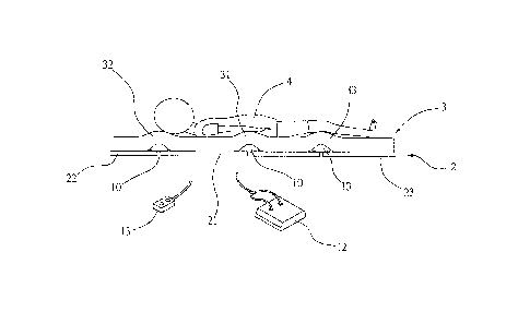
An air supply apparatus is between an air mattress and a foundation
including transverse openings. The air supply apparatus elevates the air
mattress and includes a transverse air bladder; a connection assembly
including a first line having one end connected to an outlet of an air
compressor and communicating therewith, a female connector at the other end
of the first line, a check valve in the female connector and communicating
with
the first line, a second line having the other end coupled to the air bladder
by
passing through the transverse openings so as to communicate with the air
bladder, and a male connector at one end of the second line and including a
port wherein the female connector is inserted into the male connector to
connect the check valve and the port together; and straps on a top of the
foundation for fastening the air bladder thereon.


Claims

Note: Claims are shown in the official language in which they were submitted.


What is claimed is:

1. An air supply apparatus disposed between an air mattress and a
foundation including a plurality of transverse openings, the air supply
apparatus being configured to elevate the air mattress, comprising:
at least one transverse air bladder;
an air compressor;
a connection assembly including a first line having one end connected to
an outlet of the air compressor and communicating therewith, a female
connector disposed at the other end of the first line, a check valve disposed
in
the female connector and configured to communicate with the first line, a
second line having the other end coupled to the at least one air bladder by
passing through the transverse openings so as to communicate with the at
least one air bladder, and a male connector disposed at one end of the second
line and including a port wherein the female connector is configured to insert

into the male connector to connect the check valve and the port together; and
at least one strap disposed on a top surface of the foundation for securing
the at least one air bladder onto the top surface of the foundation.
2. The air supply apparatus of claim 1, wherein the female connector
includes a check valve, and wherein the male connector includes a port.
3. The air supply apparatus of claim '1, wherein the at least one strap is

7


configured to secure the at least one air bladder to at least one of a lumbar
zone, a head zone, and a leg zone of the foundation.
4. The air supply apparatus of claim 1, wherein the number of the at least
one air bladder is two, and the plurality of air bladders are disposed on the
foundation in parallel and configured to inflate independently or as a whole.
5. The air supply
apparatus of claim 1, wherein each of the at least one air
bladder is configured to divide into two independent first and second air
bladder members which are configured to inflate independently or as a whole.

8

Description

Note: Descriptions are shown in the official language in which they were submitted.


AIR SUPPLY APPARATUS FOR AIR MATTRESS
BACKGROUND OF THE INVENTION
a) Field of the Invention
The invention relates to air mattresses and more particularly to an
improved air supply apparatus for an air mattress.
b) Description of Related Art
A conventional air supply apparatus for an air mattress comprises a
housing, an air supply disposed within the housing, a first hanger coupled to
the housing, and a second hanger coupled to the housing. The first hanger
couples the housing to a footboard in a first orientation. The second hanger
couples the housing to the footboard in a second orientation.
While the apparatus enjoys its success in the market, continuing
improvements in the exploitation of air supply apparatus for an air mattress
of
this type are constantly being sought.
SUMMARY OF THE INVENTION
It is therefore one aspect of the invention to provide an air supply
apparatus disposed between an air mattress and a foundation including a
plurality of transverse openings, the air supply apparatus being configured to
elevate the air mattress, comprising at least one transverse air bladder; an
air
CA 2972291 2017-06-30

compressor; a connection assembly including a first line having one end
connected to an outlet of the air compressor and communicating therewith, a
female connector disposed at the other end of the first line, a check valve
disposed in the female connector and configured to communicate with the first
line, a second line having the other end coupled to the at least one air
bladder
by passing through the transverse openings so as to communicate with the at
least one air bladder, and a male connector disposed at one end of the second
line and including a port wherein the female connector is configured to insert

into the male connector to connect the check valve and the port together; and
at least one strap disposed on a top surface of the foundation for securing
the
at least one air bladder onto the top surface of the foundation.
The above and other aspects, features and advantages of the invention
will become apparent from the following detailed description taken with the
accompanying drawings.
.. BRIEF DESCRIPTION OF THE DRAWINGS
FIG. 1 is an environmental view an according to a first preferred
embodiment of the invention mounted to a foundation and to be mounted with
an air mattress;
FIG. 2 is a perspective view of the air supply apparatus;
FIG. 3 is a perspective view of the assembled air supply apparatus, the
2
CA 29/2291 2017-06-30

foundation and the air mattress;
FIG. 4 is a side elevation of FIG. 3 showing a patient lying on the air
mattress and the air bladder disposed in a first position;
FIG. 5 is a view similar to FIG. 4 showing the air bladder disposed in a
second position;
FIG. 6 is a view similar to FIG. 4 showing the air bladder disposed in a third

position;
FIG. 7 is a view similar to FIG. 4 showing the air bladders disposed in a
fourth position; and
FIG. 8 is an environmental view an according to a second preferred
embodiment of the invention.
DETAILED DESCRIPTION OF THE PREFERRED EMBODIMENTS
Referring to FIGS. 1 to 6, an air supply apparatus 1 in accordance with the
invention comprises the following components as discussed in detail below.
A transverse air bladder 10 is provided. A connection assembly 11
includes a first line 110, a second line 111, a third line 112 having one end
coupled to the other ends of the first and second lines 110 and 111, a fourth
line 113 having the other end coupled to the air bladder 10, a fifth line 114
having the other end coupled to the air bladder 10, and a sixth line 115
having
the other end coupled to the air bladder 10. An air compressor 12 includes a
3
CA 2972291 2017-06-30

first inlet 120 coupled to one end of the first line 110, and a second outlet
121
coupled to one end of the second line 111. A switch 13 is electrically
connected
to the air compressor 12 for controlling the activation of the air compressor
12.
A plurality of parallel straps 14 are provided on a top surface of a
rectangular
foundation 2. The air bladder 10 is inserted through gaps between the straps
14 and the top surface of the foundation 2 and fastened on the foundation 2 by

the elastic compression of the straps 14. The foundation 2 includes a
plurality
of transverse openings 20 for allowing the other ends of the fourth, the fifth
and
the sixth lines 113, 114 and 115 to pass through to couple to the air bladder
10.
The foundation 2 further comprises a lumbar zone 21, a head zone 22, and a
leg zone 23. A rectangular, inflated air mattress 3 is placed on the
foundation 2.
A female connector 116 is provided at the other end of the third line 112.
The female connector 116 includes a check valve 1160 communicating with
the third line 112. A male connector 117 is provided at one ends of the
fourth,
.. the fifth and the sixth lines 113, 114 and 115. The male connector 117
includes
a first port 1130 communicating with the fourth line 113, a second port 1140
communicating with the fifth line 114, and a third port 1150 communicating
with
the sixth line 115 respectively. The female connector 116 is inserted into the

male connector 117 to be connected together. The air bladder 10 can be
.. inflated by performing the steps of turning on the switch 13 to activate
the air
4
CA 29/2291 2017-06-30

compressor 12, and transporting pressurized air from the air compressor 12 to
the air bladder 10 via the first and second outlets 120 and 121, the first
line 110,
the third line 112, the check valve 1160, the first, the second, and the third

ports 1130, 1140, and 1150, and the fourth, the fifth and the sixth lines 113,
114
and 115.
After turning off the switch 13, the air bladder 10 can maintain its inflated
state for a predetermined period of time duo to the provision of the check
valve
1160. The air bladder 10 can be deflated by disconnecting the female
connector 116 from the male connector 117 and expelling air in the air bladder
.. 10 to the atmosphere via the fourth, the fifth and the sixth lines 113, 114
and
115, and the first, the second, and the third ports 1130, 1140, and 1150.
As shown in FIG. 4, the air bladder 10 is disposed under a lumbar zone 31
of the air mattress 3 when a user 4 lies on the air mattress 3. This
accommodates a user 4 having such preferred position.
As shown in FIG. 5, the air bladder 10 is disposed under a head zone 32 of
the air mattress 3 when a user 4 lies on the air mattress 3. This accommodates

a user 4 having such preferred position.
As shown in FIG. 6, the air bladder 10 is disposed under a leg zone 33 of
the air mattress 3 when a user 4 lies on the air mattress 3. This accommodates
a user 4 having such preferred position.
5
CA 2972291 2017-06-30

Referring to FIG. 7 in conjunction with FIGS. 1 to 5, there are three air
bladders 10 provided. The air bladders 10 are disposed under the head zone
32, the lumbar zone 31, and the leg zone 33 of the air mattress 3
respectively.
This accommodates a user 4 having such preferred position.
Referring to FIG. 8, an air supply apparatus 1 for an air mattress in
accordance with a second preferred embodiment of the invention is shown.
The characteristics of the second preferred embodiment are substantially the
same as that of the first preferred embodiment except the following: The air
bladder 10 is divided into two independent first and second air bladder
.. members 100 and 101. The first air bladder member 100 communicates with
the fourth line 113 and the second air bladder member 101 communicates with
the sixth line 115 respectively. In use, the first air bladder member 100 can
be
inflated by opening the first port 1130 and connecting the female connector
116
and the male connector 117 together. Similarly, the second air bladder member
101 can be inflated by opening the third port 1150 and connecting the female
connector 116 and the male connector 117 together. This accommodates two
users lying on a mattress having different preferred positions.
The scope of the claims should not be limited by the preferred
embodiments set forth in the examples, but should be given the broadest
interpretation consistent with the description as a whole.
6
CA 2972291 2017-06-30

Representative Drawing
A single figure which represents the drawing illustrating the invention.
Administrative Status

For a clearer understanding of the status of the application/patent presented on this page, the site Disclaimer , as well as the definitions for Patent , Administrative Status , Maintenance Fee  and Payment History  should be consulted.

Administrative Status

Title Date
Forecasted Issue Date Unavailable
(22) Filed 2017-06-30
Examination Requested 2017-06-30
(41) Open to Public Inspection 2018-12-30
Dead Application 2019-12-10

Abandonment History

Abandonment Date Reason Reinstatement Date
2018-12-10 R30(2) - Failure to Respond
2019-07-02 FAILURE TO PAY APPLICATION MAINTENANCE FEE

Payment History

Fee Type Anniversary Year Due Date Amount Paid Paid Date
Application Fee $200.00 2017-06-30
Request for Examination $400.00 2017-06-30
Owners on Record

Note: Records showing the ownership history in alphabetical order.

Current Owners on Record
APEX HEALTH CARE MFG. INC.
Past Owners on Record
None
Past Owners that do not appear in the "Owners on Record" listing will appear in other documentation within the application.
Documents

To view selected files, please enter reCAPTCHA code :


To view images, click a link in the Document Description column. To download the documents, select one or more checkboxes in the first column and then click the "Download Selected in PDF format (Zip Archive)" or the "Download Selected as Single PDF" button.

List of published and non-published patent-specific documents on the CPD .

If you have any difficulty accessing content, you can call the Client Service Centre at 1-866-997-1936 or send them an e-mail at CIPO Client Service Centre.


Document
Description 
Date
(yyyy-mm-dd) 
Number of pages   Size of Image (KB) 
Abstract 2017-06-30 1 19
Description 2017-06-30 6 170
Claims 2017-06-30 2 41
Drawings 2017-06-30 8 72
Examiner Requisition 2018-06-08 4 204
Representative Drawing 2018-11-23 1 7
Cover Page 2018-11-23 2 40