Note: Descriptions are shown in the official language in which they were submitted.
CA 02972354 2017-06-27
- 1 -
DESCRIPTION
STATE DETECTION DEVICE AND METHOD FOR FUEL CELL
TECHNICAL FIELD
[0001] This invention relates to state detection device and method for fuel
cell.
BACKGROUND ART
[0002] A state detection device for fuel cell is known which measures a
voltage value and an impedance value of a fuel cell and detects an internal
state of the fuel cell on the basis of these values.
[0003] For example, it is proposed in Japanese Patent No. 4640661 to
calculate a first impedance in a first frequency region corresponding to an
electrolyte membrane resistance and a second impedance in a second
frequency region corresponding to the sum of the electrolyte membrane
resistance and a catalyst layer resistance and lower than the first frequency
region and calculate a water content of a catalyst layer on the basis of a
differential impedance between the second and first impedances.
[0004] Further, it is described in JP2005-285614A to acquire complex
impedances corresponding to a frequency F1 at an intersection with a real axis
of a complex impedance curve (Cole-Cole plot) of a fuel cell, a frequency F2
in a
first region expressing a reaction resistance (reaction resistance of a
cathode
electrode) when oxygen reacts and a frequency F3 in a second region
expressing a resistance concerning oxygen diffusion and obtain an internal
resistance value from the obtained complex impedances.
SUMMARY OF INVENTION
- 2 -
[0005] However, it is not possible to grasp each of state quantities of an
anode electrode and those of a cathode electrode in Japanese Patent No.
4640661. Further, it is also difficult in JP2005-285614A to individually
grasp the state of the anode electrode and that of the cathode electrode
since the state of the anode electrode and that of the cathode electrode are
mixed in the impedance curve.
[0006] The present invention was developed, focusing on such a problem,
and aims to provide a state detection device and method for fuel cell capable
of individually detecting internal state quantities such as state quantities
of an anode electrode and those of a cathode electrode in a fuel cell.
[0007] According to an aspect of the present invention there is provided
a state detection device for a fuel cell for generating power upon receiving
a supply of anode gas and cathode gas, comprising:
a controller programed to detect a state of a fuel cell stack,
wherein the controller is programed to:
acquire a high frequency impedance based on a plurality of
frequencies selected from a high frequency band and a low frequency
impedance based on one or more frequency selected from a low frequency
band, the high frequency band including an anode electrode response
frequency band which shows responsiveness to a state quantity including
a reaction resistance value of an anode electrode, the low frequency band
which shows responsiveness to a state quantity including a reaction
resistance value of a cathode electrode; and
estimate each of the state quantity of the anode electrode and the
state quantity of the cathode electrode by combining the acquired high
frequency impedance and low frequency impedance, the state quantity of
the anode electrode and the state quantity of the cathode electrode serving
as internal states of the fuel cell,
CA 2972354 2019-06-10
- 2a -
wherein the device is configured to adjust pressures and flow
rates of the anode gas and the cathode gas according to the state quantity
of the anode electrode and the state quantity of the cathode electrode.
According to another aspect of the present invention there is
provided a state detection method for a fuel cell for generating power upon
receiving a supply of anode gas and cathode gas, comprising:
a step of acquiring a high frequency impedance based on a
plurality of frequencies selected from a high frequency band and a low
frequency impedance based on one or more frequency selected from a low
frequency band, the high frequency band including an anode electrode
response frequency band which shows responsiveness to a state quantity
including a reaction resistance value of an anode electrode, the low
frequency band which shows responsiveness to a state quantity including
a reaction resistance value of a cathode electrode;
a step of estimating each of the state quantity of the anode
electrode and the state quantity of the cathode electrode serving as internal
states of the fuel cell by combining the acquired high frequency impedance
and low frequency impedance; and
a step of adjusting pressures and flow rates of the anode gas and
the cathode gas according to the state quantity of the anode electrode and
the state quantity of the cathode electrode.
BRIEF DESCRIPTION OF DRAWINGS
CA 2972354 2019-06-10
CA 02972354 2017-06-27
- 3 -
[0008] FIG. 1 is a
perspective view of a fuel cell according to an embodiment
of the present invention,
FIG. 2 is a sectional view along II-II of the fuel cell of FIG. 1,
FIG. 3 is a schematic configuration diagram of a fuel cell system
according to the embodiment of the present invention,
FIG. 4A is a diagram showing a path of a current flowing in a simplified
equivalent circuit model of a fuel cell in the case of applying an
alternating-current voltage in a low frequency band,
FIG. 4B is a diagram showing a path of a current flowing in the simplified
equivalent circuit model of the fuel cell in the case of applying an
alternating-current voltage in a frequency band higher than in the case of
FIG.
4A,
FIG. 4C is a diagram showing a path of a current flowing in the simplified
equivalent circuit model of the fuel cell in the case of applying an
alternating-current voltage in a frequency band higher than in the case of
FIG.
4B,
FIG. 4D is a diagram showing a path of a current flowing in the simplified
equivalent circuit model of the fuel cell in the case of inputting an
alternating-current voltage in a high frequency band,
FIG. 5 is a flow chart showing the flow of state quantity estimation
according to one embodiment,
FIG. 6 is a flow chart showing the flow of state quantity estimation
according to one embodiment,
FIG. 7 is a graph showing I-V characteristic curves of the fuel cell
respectively in steady time and in unsteady time,
FIG. 8 is a flow chart showing the flow of state quantity estimation
according to one embodiment,
CA 02972354 2017-06-27
- 4 -
FIG. 9 shows frequency responses of candidates for an electrical double
layer capacitance of a cathode electrode,
FIG. 10A shows frequency responses of candidates for an electrical
double layer capacitance of an anode electrode,
FIG. 10B shows frequency responses of candidates for a reaction
resistance value of the anode electrode 112,
FIG. 11 is a flow chart showing the flow of state quantity estimation
according to one embodiment,
FIG. 12 shows an I-V characteristic curve of the fuel cell 1 in steady time,
FIG. 13 is a graph showing an example of a method for setting a set of
current and voltage for the calculation of a gradient AV/4I in the I-V
characteristic curve, and
FIG. 14 is a block diagram schematically showing a main part relating to
an impedance measurement in a fuel cell system according to one
embodiment.
DESCRIPTION OF EMBODIMENTS
[0009] Hereinafter, embodiments of the present invention are described
with reference to the drawings and the like.
[0010] A fuel cell is configured such that an electrolyte membrane is
sandwiched by an anode electrode serving as a fuel electrode and a cathode
electrode serving as an oxidant electrode. The fuel cell generates power using
anode gas containing hydrogen and supplied to the anode electrode and
cathode gas containing oxygen and supplied to the cathode electrode.
Electrode reactions which proceed in both anode and cathode electrodes are as
follows.
[0011] Anode electrode: 2H2-0H++4e- ... (1)
CA 02972354 2017-06-27
- 5 -
Cathode electrode: 4H++4e-+02¨>2H20 ... (2)
FIGS. 1 and 2 are views showing the configuration of a fuel cell 10
according to one embodiment of the present invention. FIG. 1 is a perspective
view of the fuel cell 10. FIG. 2 is a sectional view along II-II of the fuel
cell 10
of FIG. 1.
[0012] As shown in FIGS. 1 and 2, the fuel cell 10 includes a membrane
electrode assembly (MEA) 11, and an anode separator 12 and a cathode
separator 13 arranged to sandwich the MEA 11.
[0013] The MEA 11 is composed of an electrolyte membrane 111, an anode
electrode 112 and a cathode electrode 113. The MEA 11 includes the anode
electrode 112 on one surface side of the electrolyte membrane 111 and the
cathode electrode 113 on the other surface side.
[0014] The electrolyte membrane 111 is a proton conductive ion exchange
membrane formed of fluororesin. The electrolyte membrane 111 exhibits
good electrical conductivity in a wet state. It should be noted that another
material such as a material having a phosphoric acid (H3PO4) impregnated in a
predetermined matrix may be used according to a possible response of a fuel
cell.
[0015] The anode electrode 112 includes a catalyst layer 112A and a gas
diffusion layer 112B. The catalyst layer 112A is a member formed of platinum
or carbon black particles carrying platinum or the like and provided in
contact
with the electrolyte membrane 111. The gas diffusion layer 112B is provided
on an outer side of the catalyst layer 112A. The gas diffusion layer 112B is a
member formed of carbon cloth having gas diffusion property and electrical
conductivity and provided in contact with the catalyst layer 112A and the
anode separator 12.
[0016] Similarly to the anode electrode 112, the cathode electrode 113 also
CA 02972354 2017-06-27
- 6 -
includes a catalyst layer 113A and a gas diffusion layer 113B. The catalyst
layer 113A is arranged between the electrolyte membrane 111 and the gas
diffusion layer 113B and the gas diffusion layer 113B is arranged between the
catalyst layer 113A and the cathode separator 13.
[0017] The anode separator 12 is arranged on an outer side of the gas
diffusion layer 112B. The anode separator 12 includes a plurality of anode
gas flow passages 121 for supplying anode gas (hydrogen gas) to the anode
electrode 112. The anode gas flow passages 121 are formed as groove-like
passages.
[0018] The cathode separator 13 is arranged on an outer side of the gas
diffusion layer 113B. The cathode separator 13 includes a plurality of
cathode gas flow passages 131 for supplying cathode gas (air) to the cathode
electrode 113. The cathode gas flow passages 131 are formed as groove-like
passages.
[0019] The anode separator 12 and the cathode separator 13 are so
configured that the anode gas flowing in the anode gas flow passages 121 and
the cathode gas flowing in the cathode gas flow passages 131 flow in
directions
opposite to each other. It should be noted that the anode separator 12 and
the cathode separator 13 may be so configured that these gases flow in the
same direction.
[0020] In the case of using such a fuel cell 10 as a power source for an
automotive vehicle, a fuel cell stack in which several hundreds of fuel cells
10
are laminated is used since required power is large. Power for driving the
vehicle is taken out by configuring a fuel cell system for supplying anode gas
and cathode gas to the fuel cell stack. It should be noted that although an
impedance measurement to be described later is conducted for each fuel cell
stack in which the fuel cells 10 are laminated in the present embodiment, the
CA 02972354 2017-06-27
- 7 -
impedance measurement may be conducted for each fuel cell 10 or for each
part (e.g. several tens of cells) of the fuel cell stack.
[0021] Further, in the fuel cell stack, an anode electrode, a cathode
electrode and an electrolyte membrane serving as sums are configured by
arranging the anode electrodes 112, the cathode electrodes 113 and the
electrolyte membranes 111 of a plurality of the fuel cells 10 in series.
However, for the convenience of description, these anode electrode, cathode
electrode and electrolyte membrane serving as the sums are also denoted by
the same reference signs as the anode electrode 112, the cathode electrode 113
and the electrolyte membrane 111 of the single cell.
[0022] FIG. 3 is a schematic diagram of a fuel cell system 100 according to
one embodiment of the present invention.
[0023] The fuel cell system 100 includes a fuel cell 1, a cathode gas
supplying/discharging device 2, an anode gas supplying/discharging device 3,
a power system 5 and a controller 6.
[0024] The fuel cell 1 is a laminated battery formed by laminating a
plurality of fuel cells 10 (unit cells) as described above. The fuel cell 1
generates power necessary to drive a vehicle upon receiving the supply of the
anode gas and the cathode gas. The fuel cell 1 includes an anode electrode
side terminal 1A and a cathode electrode side terminal 1B as output terminals
for taking out power.
[0025] The cathode gas supplying/discharging device 2 supplies the
cathode gas to the fuel cell 1 and discharges cathode off-gas discharged from
the fuel cell 1 to outside. The cathode gas supplying/discharging device 2
includes a cathode gas supply passage 21, a cathode gas discharge passage 22,
a filter 23, an air flow sensor 24, a cathode compressor 25, a cathode
pressure
sensor 26, a water recovery device (WRD) 27 and a cathode pressure control
CA 02972354 2017-06-27
- 8 -
valve 28.
[0026] The cathode gas supply passage 21 is a passage in which the
cathode gas to be supplied to the fuel cell 1 flows. One end of the cathode
gas
supply passage 21 is connected to the filter 23 and the other end is connected
to a cathode gas inlet part of the fuel cell 1.
[0027] The cathode gas discharge passage 22 is a passage in which the
cathode off-gas discharged from the fuel cell 1 flows. One end of the cathode
gas discharge passage 22 is connected to a cathode gas outlet part of the fuel
cell 1 and the other end is formed as an opening end. The cathode off-gas is
mixture gas containing the cathode gas, steam produced by the electrode
reaction and the like.
[0028] The filter 23 is a member for removing dust, dirt and the like
contained in the cathode gas to be taken into the cathode gas supply passage
21.
[0029] The cathode compressor 25 is provided downstream of the filter 23
in the cathode gas supply passage 21. The cathode compressor 25 supplies
the cathode gas in the cathode gas supply passage 21 to the fuel cell 1 by
feeding the cathode gas under pressure.
[0030] The air flow sensor 24 is provided between the filter 23 and the
cathode compressor 25 in the cathode gas supply passage 21. The air flow
sensor 24 detects a flow rate of the cathode gas to be supplied to the fuel
cell 1.
[0031] The cathode pressure sensor 26 is provided between the cathode
compressor 25 and the WRD 27 in the cathode gas supply passage 21. The
cathode pressure sensor 26 detects a pressure of the cathode gas to be
supplied to the fuel cell 1. The cathode gas pressure detected by the cathode
pressure sensor 26 represents a pressure of an entire cathode system
including the cathode gas flow passages of the fuel cell 1 and the like.
CA 02972354 2017-06-27
- 9 -
[0032] The WRD 27 is connected over the cathode gas supply passage 21
and the cathode gas discharge passage 22. The WRD 27 is a device for
recovering moisture in the cathode off-gas flowing in the cathode gas
discharge
passage 22 and humidifying the cathode gas flowing in the cathode gas supply
passage 21 with that recovered moisture.
[0033] The cathode pressure control valve 28 is provided downstream of the
WRD 27 in the cathode gas discharge passage 22. The cathode pressure
control valve 28 is controlled to open and close by the controller 6 and
adjusts
the pressure of the cathode gas to be supplied to the fuel cell 1.
[0034] Next, the anode gas supplying/discharging device 3 is described.
[0035] The anode gas supplying/discharging device 3 supplies the anode
gas to the fuel cell 1 and discharges anode off-gas discharged from the fuel
cell
1 to the cathode gas discharge passage 22. The anode gas
supplying/discharging device 3 includes a high-pressure tank 31, an anode
gas supply passage 32, an anode pressure control valve 33, an anode pressure
sensor 34, an anode gas discharge passage 35, a buffer tank 36, a purge
passage 37 and a purge valve 38.
[0036] The high-pressure tank 31 is a container for storing the anode gas
to
be supplied to the fuel cell 1 in a high-pressure state.
[0037] The anode gas supply passage 32 is a passage for supplying the
anode gas discharged from the high-pressure tank 31 to the fuel cell 1. One
end of the anode gas supply passage 32 is connected to the high-pressure tank
31 and the other end is connected to an anode gas inlet part of the fuel cell
1.
[0038] The anode pressure control valve 33 is provided downstream of the
high-pressure tank 31 in the anode gas supply passage 32. The anode
pressure control valve 33 is controlled to open and close by the controller 6
and adjusts the pressure of the anode gas to be supplied to the fuel cell 1.
CA 02972354 2017-06-27
- 10 -
[0039] The anode pressure sensor 34 is provided downstream of the anode
pressure control valve 33 in the anode gas supply passage 32. The anode
pressure sensor 34 detects a pressure of the anode gas to be supplied to the
fuel cell 1. The anode gas pressure detected by the anode pressure sensor 34
represents a pressure of an entire anode system including the buffer tank 36,
the anode gas flow passages of the fuel cell 1 and the like.
[0040] The anode gas discharge passage 35 is a passage in which the anode
off-gas discharged from the fuel cell 1 flows. One end of the anode gas
discharge passage 35 is connected to an anode gas outlet part of the fuel cell
1
and the other end is connected to the buffer tank 36. The anode off-gas
contains the anode gas not used in the electrode reaction, impurity gas such
as nitrogen having leaked from the cathode gas flow passages 131 to the anode
gas flow passages 121, moisture and the like.
[0041] The buffer tank 36 is a container for temporarily storing the anode
off-gas flowing from the anode gas discharge passage 35. The anode off-gas
pooled in the buffer tank 36 is discharged to the cathode gas discharge
passage 22 through the purge passage 37 when the purge valve 38 is opened.
[0042] The purge passage 37 is a passage for discharging the anode off-gas.
One end of the purge passage 37 is connected to the anode gas discharge
passage 35 and the other end is connected to a part of the cathode gas
discharge passage 22 downstream of the cathode pressure control valve 28.
[0043] The purge valve 38 is provided in the purge passage 37. The purge
valve 38 is controlled to open and close by the controller 6 and controls a
purge
flow rate of the anode off-gas discharged from the anode gas discharge passage
35 to the cathode gas discharge passage 22.
[0044] When a purge control is executed to open the purge valve 38, the
anode off-gas is discharged to outside through the purge passage 37 and the
CA 02972354 2017-06-27
- 11 -
cathode gas discharge passage 22. At this time, the anode off-gas is mixed
with the cathode off-gas in the cathode gas discharge passage 22. By mixing
the anode off-gas and the cathode off-gas and discharging the mixture gas to
outside in this way, an anode gas concentration (hydrogen concentration) in
the mixture gas is set at a value not larger than a discharge allowable
concentration.
[0045] The power system 5 includes a current sensor 51, a voltage sensor
52, a travel motor 53, an inverter 54, a battery 55 and a DC/DC converter 56.
[0046] The current sensor 51 detects an output current extracted from the
fuel cell 1. The voltage sensor 52 detects an output voltage of the fuel cell
1,
i.e. an inter-terminal voltage between the anode electrode side terminal lA
and
the cathode electrode side terminal 1B. The voltage sensor 52 may be
configured to detect a voltage of each fuel cell 10 or may be configured to
detect
a voltage of each group composed of a plurality of the fuel cells 10.
[0047] The travel motor 53 is a three-phase alternating-current
synchronous motor and a drive source for driving wheels. The travel motor
53 has a function serving as a motor to be rotationally driven upon receiving
the supply of power from the fuel cell 1 and the battery 55 and a function
serving as a generator for generating power by being rotationally driven by an
external force.
[0048] The inverter 54 is composed of a plurality of semiconductor switches
such as IGBTs. The semiconductor switches of the inverter 54 are
switching-controlled by the controller 6, thereby converting direct-current
power into alternating-current power or alternating-current power into
direct-current power. The inverter 54 converts composite direct-current
power of output power of the fuel cell 1 and output power of the battery 55
into
three-phase alternating-current power and supplies this power to the travel
CA 02972354 2017-06-27
- 12 -
motor 53 when the travel motor 53 is caused to function as the motor. In
contrast, the inverter 54 converts regenerative power (three-phase
alternating-current power) of the travel motor 53 into direct-current power
and
supplies this power to the battery 55 when the travel motor 53 is caused to
function as the generator.
[0049] The battery 55 is configured to be charged with a surplus of the
output power of the fuel cell 1 and the regenerative power of the travel motor
53. The power charged into the battery 55 is supplied to the travel motor 53
and auxiliary machines such as the cathode compressor 25 if necessary.
[0050] The DC/DC converter 56 is a bidirectional voltage converter for
increasing and decreasing the output voltage of the fuel cell 1. By
controlling
the output voltage of the fuel cell 1 by the DC/DC converter 56, the output
current of the fuel cell 1 and the like are adjusted.
[0051] The controller 6 is configured by a microcomputer including a
central processing unit (CPU), a read-only memory (ROM), a random access
memory (RAM) and an input/output interface (I/O interface). To the
controller 6 are input signals from sensors such as an accelerator stroke
sensor (not shown) for detecting a depressed amount of an accelerator pedal
besides signals from various sensors such as the current sensor 51 and the
voltage sensor 52.
[0052] The controller 6 adjusts the pressures and flow rates of the anode
gas and the cathode gas to be supplied to the fuel cell 1 by controlling the
anode pressure control valve 33, the cathode pressure control valve 28, the
cathode compressor 25 and the like according to an operating state of the fuel
cell system 100.
[0053] Further, the controller 6 calculates target output power on the
basis
of power required by the travel motor 53, power required by the auxiliary
CA 02972354 2017-06-27
- 13 -
machines such as the cathode compressor 25, charge/discharge requests of
the battery 55 and the like. The controller 6 calculates a target output
current of the fuel cell 1 on the basis of the target output power by
referring to
an IV characteristic (current-voltage characteristic) of the fuel cell 1
determined in advance. Then, the controller 6 controls the output voltage of
the fuel cell 1 by the DC/DC converter 56 such that the output current of the
fuel cell 1 reaches the target output current, and executes a control to
supply a
necessary current to the travel motor 53 and the auxiliary machines.
[0054] Further, the controller 6 controls the cathode compressor 25 and
the like such that a degree of wetness (water content) of each electrolyte
membrane 111 of the fuel cell 1 is in a state suitable for power generation.
[0055] Further, the controller 6 calculates an impedance Z of the fuel cell
1
at a predetermined frequency by dividing an amplitude value of a voltage
value,
in which an alternating-current signal of the predetermined frequency is
superimposed on an output voltage of the fuel cell 1, by an amplitude value of
a current value likewise superimposed with an alternating-current signal in
first to sixth embodiments described later.
[0056] In the fuel cell system 100 described as above, a state detection
device for the fuel cell 1 is configured by the controller 6, the current
sensor 51,
the voltage sensor 52 and the DC/DC converter 56.
[0057] In the present embodiment, a simplified equivalent circuit model
taking into account of a reaction resistance Ra and an electrical double layer
capacitance Ca, which are state quantities of the anode electrode 112 in the
fuel cell 1, a reaction resistance Rc and an electrical double layer
capacitance
Cc, which are state quantities of the cathode electrode 113, and an
electrolyte
membrane resistance value Rai, which is a state quantity of the electrolyte
membrane 111, is set and a state of the fuel cell 1 is estimated on the basis
of
CA 02972354 2017-06-27
- 14 -
this simplified equivalent circuit model.
[0058] It should be noted that the electrolyte membrane resistance value
Rm is a state quantity whose value is determined according to a degree of
wetness of the electrolyte membrane 111. Normally, as the electrolyte
membrane 111 becomes drier, the electrolyte membrane resistance value Rm
tends to increase.
[0059] Further, the reaction resistance value Ra of the anode electrode 112
increases and decreases according to the reaction of the anode gas in the
anode electrode 112. For example, if there is a factor due to which the
reaction does not smoothly proceed such as a shortage of the anode gas, the
reaction resistance value Ra increases according to this.
[0060] Furthermore, the electrical double layer capacitance Ca of the anode
electrode 112 is modeled to represent an electrical capacitance of the anode
electrode 112 in the fuel cell 1. Thus, the electrical double layer
capacitance
Ca is determined on the basis of various elements such as a constituting
material, the size and the like of the anode electrode 112.
[0061] Further, the reaction resistance value Re of the cathode electrode
113 increases and decreases according to the reaction of the cathode gas in
the
cathode electrode 113. For example, if there is a factor due to which the
reaction does not smoothly proceed such as a shortage of the cathode gas, the
reaction resistance value Re increases according to this.
[0062] Furthermore, the electrical double layer capacitance Ce of the
cathode electrode 113 is modeled to represent an electrical capacitance of the
cathode electrode 113. Thus, the electrical double layer capacitance value Cc
is determined on the basis of various elements such as a constituting
material,
the size and the like of the cathode electrode 113.
[0063] Here, the present inventors found out that there was a frequency
CA 02972354 2017-06-27
- 15 -
dependent characteristic in a path, along which an alternating-current signal
(alternating current) superimposed on an output current of the fuel cell 1
flowed in the fuel cell, in the simplified equivalent circuit model of the
fuel cell
1. The frequency dependent characteristic in the path along which the
alternating current flows in the fuel cell is described below.
[0064] FIGS. 4A to 4D are diagrams schematically showing a path, along
which an alternating current superimposed on an output current of the fuel
cell 1 flows, in the equivalent circuit model of the fuel cell 1 according to
the
present embodiment for each frequency band of the alternating current.
[0065] FIG. 4A shows a path of an alternating current of a frequency
belonging to a low frequency band, for example, near 0 Hz (hereinafter, also
written as a first frequency band). Further, FIG. 4B shows a path of an
alternating current of a frequency belonging to a frequency band slightly
higher than the first frequency band by about several Hz (hereinafter, also
written as a second frequency band). Furthermore, FIG. 4C shows a path of
an alternating current of a frequency belonging to a frequency band slightly
higher than the second frequency band by about several tens of Hz to several
KHz (hereinafter, also written as a third frequency band). Further, FIG. 4D
shows a path of an alternating current of a frequency belonging to a highest
frequency band of several tens of KHz or higher (hereinafter, also written as
a
fourth frequency band). Note that the path of the alternating current is
shown by a thick line in FIGS. 4A to 4D.
[0066] First, the value of the alternating current of the frequency
belonging
to the first frequency band shown in FIG. 4A moderately varies since the
frequency is low, and properties of the alternating current are close to those
of
a direct current having a constant current value. Thus, the alternating
current having the properties close to those of the direct current does not
flow
CA 02972354 2017-06-27
- 16 -
to the electrical double layer capacitance of the anode electrode 112 and the
electrical double layer capacitance of the cathode electrode 113 or, even if
the
alternating current flows, the magnitude thereof is small to a negligible
extent.
Specifically, as shown in FIG. 4A, the alternating current substantially flows
only to the reaction resistance of the anode electrode 112, the electrolyte
membrane resistance and the reaction resistance of the cathode electrode 113.
[0067] Next, the value of the alternating current of the frequency
belonging
to the second frequency band shown in FIG. 4B more largely varies as
compared to the alternating current of the frequency belonging to the first
frequency band, and properties as the alternating current are intensified.
Thus, as shown in FIG. 4B, the alternating current is thought to start flowing
also toward the electrical double layer capacitance of the cathode electrode
113.
10068] On the other hand, since the reaction resistance value Ra of the
anode electrode 112 is known to have a much smaller value than the reaction
resistance value Rc of the cathode electrode 113, the current relatively
easily
flows toward the reaction resistance of the anode electrode 112. Thus, it is
thought that the alternating current of the frequency in the second frequency
band still does not flow toward the electrical double layer capacitance part
of
the anode electrode 112 or, even if the alternating current flows, the
magnitude thereof is small to a negligible extent.
[0069] Further, the value of the alternating current of the frequency
belonging to the third frequency band shown in FIG. 4C more largely varies as
compared to the alternating current of the frequency belonging to the second
frequency band, and properties as the alternating current are further
intensified. Thus, the influence of the electrical double layer capacitance of
the anode electrode 112 can be no longer ignored and the current is thought to
CA 02972354 2017-06-27
- 17 -
flow also to the electrical double layer capacitance of the anode electrode
112.
[0070] On the other hand, in this third frequency band, an
oxidation/reduction reaction in the cathode electrode 113 cannot follow a
variation speed of the value of the above alternating current and a state
occurs
in which this oxidation/reduction reaction does not apparently occur.
[0071] Accordingly, the cathode gas substantially does not react in the
cathode electrode 113, wherefore the influence of the reaction resistance of
the
cathode electrode 113 due to the above oxidation/reduction reaction can be
ignored.
[00721 Specifically, in the third frequency band, the alternating current
does not flow to the reaction resistance of the cathode electrode 113 or, even
if
the alternating current flows, the magnitude thereof is small to a negligible
extent. Thus, the alternating current is thought to substantially flow only to
the electrical double layer capacitance component.
[0073] It should be noted that performance of the oxidation/reduction
reaction to follow a variation of the value of the alternating current is
relatively
high in the anode electrode 112 and this oxidation/reduction reaction can
still
follow the variation of the value of the alternating current in the third
frequency band. Thus, as shown in FIG. 4C, the alternating current of the
frequency belonging to the third frequency band is thought to still flow
through
the reaction resistance of the anode electrode 112.
[0074] The value of the alternating current of the frequency belonging to
the fourth frequency band shown in FIG. 4D even more largely varies as
compared to the alternating current of the frequency belonging to the third
frequency band, wherefore not only the oxidation/reduction reaction in the
cathode electrode 113, but also the oxidation/reduction reaction in the anode
electrode 112 can no longer follow the variation of the value of this
alternating
CA 02972354 2017-06-27
- 18 -
current.
[0075] Accordingly, the reaction substantially does not occur in the anode
electrode 112 in addition to in the cathode electrode 113, and the influence
of
both the reaction resistance of the cathode electrode 113 and that of the
anode
electrode 112 can be ignored.
[0076] Specifically, in the fourth frequency band, the alternating current
does not flow to the reaction resistances of both the cathode electrode 113
and
the anode electrode 112 or, even if the alternating current flows, the
magnitude thereof is small to a negligible extent. Thus, as shown in FIG. 4D,
the alternating current of the frequency belonging to the fourth frequency
band is thought to flow only toward the electrical double layer capacitance of
each of the cathode electrode 113 and the anode electrode 112.
[0077] As is understood from the above description, the paths along which
the alternating current of the frequency selected from the aforementioned
first
frequency band, the alternating current of the frequency selected from the
aforementioned second frequency band, the alternating current of the
frequency selected from the aforementioned third frequency band and the
alternating current of the frequency selected from the aforementioned fourth
frequency band flow to each element in the simplified equivalent circuit of
the
fuel cell differ.
[0078] Accordingly, the present inventors arrived at individual estimation
of various state quantities from impedances based on frequencies belonging to
each frequency band with reference to the following equation for impedance
obtained on the basis of the simplified equivalent circuit utilizing
differences of
the paths of the alternating currents corresponding to the frequencies as just
described:
[Equation 1]
CA 02972354 2017-06-27
- 19 -
Ra (1 ¨ j wCaRa ) + Rc ¨ j coCcRc
(1)
Z = + l 021-1D 2 2 ()2c2R2
"-a c c
(where j denotes an imaginary unit).
[0079] For example, the alternating current of the frequency selected from
the above fourth frequency band (hereinafter, also written as an "electrolyte
membrane response frequency band") flows to the electrolyte membrane
resistance, the electrical double layer capacitance of the anode electrode 112
and the electrical double layer capacitance of the cathode electrode 113.
Thus, the impedance based on the frequency selected from this electrolyte
membrane response frequency band (hereinafter, also written as an
"electrolyte membrane response impedance") includes information of the
electrolyte membrane resistance value R..
[0080] It should be noted that this electrolyte membrane response
frequency band is a frequency band used in so-called HFR (High Frequency
Resistance) measurement. Thus, if co¨>09 is assumed in Equation (1) for
impedance, the impedance Z can be regarded to substantially match the
electrolyte membrane resistance value R..
[0081] Further, the alternating current of the frequency selected from the
third frequency band (hereinafter, also written as an "anode electrode
response
frequency band") flows to the electrolyte membrane resistance, the reaction
resistance of the anode electrode 112, the electrical double layer capacitance
of
the anode electrode 112 and the electrical double layer capacitance of the
cathode electrode 113. Thus, the impedance based on the frequency selected
from this anode electrode response frequency band (hereinafter, also written
as an "anode electrode response impedance") includes information of at least
the reaction resistance value Ra of the anode electrode 112 and the electrical
CA 02972354 2017-06-27
- 20 -
double layer capacitance value Ca of the anode electrode 112.
[0082] Particularly, since the reaction resistance of the cathode electrode
113 can be ignored in the equivalent circuit shown in FIG_ 4C in this case,
the
following equation for impedance is given.
[Equation 2]
Z =
Ra coCaRa ) . 1
+
1+ CO2C2R2 0)Cc (2)
a a
[0083] Further, the alternating current of the frequency selected from the
second frequency band flows to the electrolyte membrane resistance, the
reaction resistance of the anode electrode 112, the reaction resistance of the
cathode electrode 113 and the electrical double layer capacitance of the
cathode electrode 113. Thus, the impedance based on the frequency selected
from this second frequency band includes information of the electrolyte
membrane resistance value, the reaction resistance value of the anode
electrode 112, the reaction resistance value IR, of the cathode electrode 113
and the electrical double layer capacitance value Cc of the cathode electrode
113 as state quantities.
[0084] Furthermore, the alternating current of the frequency selected from
the first frequency band (hereinafter, also written as a "low frequency
band"),
which is a lowest frequency band, flows to the electrolyte membrane
resistance,
the reaction resistance of the anode electrode 112 and the reaction resistance
of the cathode electrode 113. Thus, the impedance based on the frequency
selected from this low frequency band (hereinafter, also written as an "low
frequency response impedance") includes information of at least the reaction
resistance value Rc of the cathode electrode 113.
CA 02972354 2017-06-27
- 21 -
[0085] The estimation of each state quantity using at least two of the
above
electrolyte membrane response frequency band, anode electrode response
frequency band and low frequency band is described in detail in each
embodiment below.
[0086] It should be noted that it is generally known that there is a
relationship of o.) = 27cf between a "frequency f and an "angular frequency
of,
and there is only a difference multiplied by a dimensionless constant 27E
between these. Thus, the "frequency" and the 'angular frequency" are
identified with each other and a symbol "o" is used in expressing the both to
facilitate description in each embodiment.
[0087] (First Embodiment)
A first embodiment is described below.
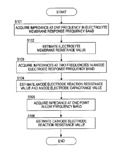
[0088] FIG. 5 is a flow chart showing the flow of state quantity estimation
according to the present embodiment.
[0089] As shown, first in Step S101, a frequency (pH at one point in the
electrolyte membrane response frequency band is selected and an impedance
Z ((OH) based on the frequency (OH is obtained.
[0090] Specifically, the controller 6 controls the DC/DC converter 56 such
that an alternating-current signal of the frequency coli in the electrolyte
membrane response frequency band is superimposed on an output voltage
and an output current output from the fuel cell 1 at an impedance
measurement timing.
[0091] Further, the controller 6 applies a Fourier transform processing on
a
value V of the output voltage measured by the voltage sensor 52 to obtain a
voltage amplitude value V(oH), applies a Fourier transform processing on a
value I of the output current measured by the current sensor 51 to obtain a
current amplitude value *on) and obtains a ratio V(oH)/I(eH) of these as the
CA 02972354 2017-06-27
- 22 -
impedance Z(cos). It should be noted that since a method for measuring the
impedance Z(coi-t) is similar also in the case of measurement for the
frequency
selected from the anode electrode response frequency band or the low
frequency band other than the electrolyte membrane response frequency band,
detailed description is omitted hereinafter.
[0092] Subsequently, in Step S102, the controller 6 estimates the
electrolyte membrane resistance value R. from the obtained impedance Z(con).
Specifically, since the electrolyte membrane response frequency band is a
frequency band used in the so-called HFR measurement as described above,
the impedance Z(con) based on the frequency n selected from this high
frequency band or a real component Zr(0)H) thereof substantially matches the
electrolyte membrane resistance value R.. Specifically, the value of the
impedance Z(0H) or the real component Zr(con) thereof is directly estimated as
the electrolyte membrane resistance value R..
[0093] In Step S103, the controller 6 selects frequencies en, co2 at two
points
in the anode electrode response frequency band and obtains anode electrode
response impedances Z(en.), Z(co2) based on these frequencies an, 02.
[0094] In Step S104, the controller 6 estimates the reaction resistance
value Ra of the anode electrode 112 and the electrical double layer
capacitance
value Ca of the anode electrode 112 from the estimated electrolyte membrane
resistance value R. and the obtained two impedances Z(coi), 402)-
[0095] A mode of this estimation is specifically described. First, in the
case of selecting the frequencies col, (02 at the two points in the anode
electrode
response frequency band, the reaction resistance of the cathode electrode 113
can be ignored as described above. Thus, Equation (2) obtained by removing
the reaction resistance value Re of the cathode electrode 113 from Equation
(1)
for impedance based on the simplified equivalent circuit can be used as an
CA 02972354 2017-06-27
- 23 -
equation for impedance.
[0096] Here, the frequencies
WI, 002 at the two points, which are known
values, and a combination of the impedances Z(01) and Z(w2) based on these
are substituted into in Equation (2) and real components Zr(W1) and Zr(w2) of
the impedances Z(on) and Z(w2) are taken. Considering that the estimated
electrolyte membrane resistance value R. is known, two equations with Ra and
Ca serving as unknowns are obtained. Thus, Ra and Ca can be obtained if the
obtained two equations are solved.
[0097] An example of a method for obtaining the unknowns Ra and Ca is
described. First, if the real component of Equation (2) is taken and changed,
the following equation is obtained.
[Equation 3]
1 R
______ 0)2C2R m
( 3 )
Zr a Ra Zrr-Rm Considering
a plane with co2 represented on a horizontal axis and 1/Zr
represented on a vertical axis, a straight line is represented by Equation (3)
on
this plane and a gradient mr thereof is given by the following equation.
[Equation 4]
Mr = Ca a
2R ( 4 )
Here, the frequencies coi, 0)2 at the two points are known. Thus, if these
frequencies coi, co2 at the two points and the real components Zr(wi) and
Zr(W2)
of the impedance measurement values corresponding to these frequencies are
plotted on the above plane, a straight line connecting these points is
determined and the value of the gradient mr is determined. Specifically,
CA 02972354 2017-06-27
- 24 -
unknowns of Equation (4) are R. and C..
[0098] Subsequently, an intercept a of the straight line represented by
Equation (3) is given by the following equation.
[Equation 5]
1 Rm
a=-- ( 5 )
Ra Zrr¨ Rm
Here, the value of the intercept a is determined by the frequencies col, w2 at
the
points and the real components Zri and Zr2 of the impedance measurement
values corresponding to these frequencies similarly to the value of the
gradient
m,-. Since Zr is equivalent to the real components Z.A. and Zr 2 of the
impedance
measurement values, only R. is unknown in Equation (5).
[0099] Thus, according to Equation (5), the reaction resistance value Ra of
the anode electrode 112 can be obtained as follows.
[Equation 6]
R = r r¨Rm ( 6 )
a Zr a(Zr ¨ Rm )+ R
[0100] Further, by substituting R. determined by Equation (6) into
Equation (4), the electrical double layer capacitance value C. of the anode
electrode 112 can be obtained as follows.
[Equation 7]
C a = ( 7 )
M ______________ r
\IR a
CA 02972354 2017-06-27
- 25 -
[0101] It should be noted that a method for calculating R. and Ca is not
limited to the above calculation method and various suitable calculation
methods can be used.
[0102] Subsequently, in Step 105, the controller 6 selects a frequency um,
at
one point in the low frequency band and measures an impedance Z(COL) based
on this frequency em.,.
[0103] In Step S106, the controller 6 estimates the electrical double layer
capacitance value Cc of the cathode electrode 113 using the already estimated
electrolyte membrane resistance value Rm, reaction resistance value Ra of the
anode electrode 112 and electrical double layer capacitance value Ca of the
anode electrode 112 and the measured impedance Z(m).
[0104] A mode of this estimation is specifically described. An alternating
current of the frequency om, in the low frequency band flows to all the
circuit
elements in the simplified equivalent circuit of the fuel cell 1, i.e. the
reaction
resistance and the electrical double layer capacitance of the anode electrode
112, the electrolyte membrane resistance and the reaction resistance and the
electrical double layer capacitance of the cathode electrode 113 as described
above. Thus, the low frequency impedance Z(m) obtained on the basis of the
frequency col, includes information of the reaction resistance Ra and the
electrical double layer capacitance Ca of the anode electrode 112, the
electrolyte membrane resistance Rm and the reaction resistance Re and the
electrical double layer capacitance Cc of the cathode electrode 113. Thus,
Equation (1) taking into account of all the above circuit elements needs to be
used as the equation for impedance.
CA 02972354 2017-06-27
- 26 -
[0105] The frequency coL, which is a known value, and the impedance Z(ox)
based on this frequency are substituted into Equation (1), and a real
component Zr(L) and an imaginary component Zi (cm.,) are taken. Considering
that the estimated electrolyte membrane resistance value Rm, reaction
resistance value R. of the anode electrode 112 and electrical double layer
capacitance Ca of the anode electrode 112 are known, two equations with Re
and Cc serving as unknowns are obtained. Thus, the unknowns Re and Ce
can be obtained if these two equations are solved.
[0106] An example of a method for obtaining the unknowns Rc and Cc is
described. First, if the real component of Equation (1) is taken and changed,
the following equation is obtained.
[Equation 8]
R R
Zr = R + a c (8)
m 1+ (02C2R2 1+ W2C2R2
a a c c
[0107] Further, if the imaginary component of Equation (1) is taken and
changed, the following equation is obtained.
[Equation 9]
¨ COCaRa
Zi = _________________________ c
( 9)
1+ (1)2C 2R2 1+ (02C2R2
a a c c
[0108] Here, the frequency (Du, the real component Zr(0L) and the imaginary
component Zi(m) of the impedance measurement value corresponding to the
frequency ex and R. and C. are known. If these are substituted into
Equations (8) and (9) and Equations are changed, the electrical double layer
capacitance value Cc of the cathode electrode 113 is as follows.
CA 02972354 2017-06-27
- 27 -
[Equation 10]
1 ilite ¨A
Ce = ______________________________________ (10)
co Re A
[0109] In Equation (10), w is cor, and A is defined as in the following
Equation (11).
[0110]
[Equation 11]
R
A = Z R a (11)
r
m 1+ (021-12-pp, 2
[0111] Further, the reaction resistance value Re of the cathode electrode
113 is obtained as follows.
[Equation 12]
1 - 2B2 .. ¨ 4B2
R = _________________________ A +A (12)
C
2B
[0112] A in Equation (12) is defined as in the above Equation (11) and B in
Equation (12) is defined as in the following Equation (13).
[0113] [Equation 13]
COC a R a
B =Z; + (13)
1+ w2ca2Ra2
[0114] As described above, the electrolyte membrane resistance value Rm,
CA 02972354 2017-06-27
- 28 -
the reaction resistance value Ra of the anode electrode 112, the electrical
double layer capacitance value Ca of the anode electrode 112, the reaction
resistance value Rc of the cathode electrode 113 and the electrical double
layer
capacitance value Cc of the cathode electrode 113 are estimated as the state
quantities of the fuel cell 1 by Steps S101 to S106.
[0115] According to the present embodiment described above, the following
effects can be obtained. In the present embodiment, the state detection
device is configured by the controller 6, the current sensor 51, the voltage
sensor 52 and the DC/DC converter 56. Further, impedance acquisition unit
and internal state quantity estimation unit are configured by the controller
6.
[0116] According to the present embodiment, the impedance acquisition
unit of the state detection device for the fuel cell 1 for generating power
upon
receiving the supply of the anode gas and the cathode gas acquires the high
frequency impedances Z(coH), Z(wi) and Z(w2) based on the frequencies cox, w 1
and (02 selected from the high frequency band (anode electrode response
frequency band and electrolyte membrane response frequency band) including
a frequency band which shows responsiveness at least to the state quantities
Ra, Ca of the anode electrode 112 and the low frequency impedance Z(0)0 based
on the frequency (DT, selected from the low frequency band including a
frequency band which shows responsiveness at least to the state quantities
/2,,
Cc of the cathode electrode (Step S101, Step S103, Step S105).
[0117] The internal state quantity estimation unit of the state detection
device for the fuel cell 1 estimates each of the state quantities Ra, Ca of
the
anode electrode 112 and the state quantities Rc, Cc of the cathode electrode
113 serving as the internal states of the fuel cell 1 by combining the
obtained
CA 02972354 2017-06-27
- 29 -
high frequency impedances Z(oa), Z(o)I) and Z(6)2) and low frequency
impedance Z(wi,).
[0118] According to this, at least each of the state quantities R., C. of
the
anode electrode 112 and the state quantities Re, Cc of the cathode electrode
113 can be individually detected on the basis of the obtained high frequency
impedances Z(coH), Z(on) and Z(o2) and low frequency impedance Z(ex.), i.e.
impedance information obtained from the different frequency bands, utilizing a
following speed difference of the reaction of the anode electrode 112 and the
reaction of the cathode electrode 113 in response to a current variation
according to the magnitude of the frequency. Thus, highly accurate
information of the state quantities Ra, Ca of the anode electrode 112 and the
state quantities (Re, Ce) of the cathode electrode 113 can be obtained, with
the
result that an operation control of the fuel cell 1 executed utilizing these
state
quantities can be made more proper.
[0119] Further, according to the present embodiment, the internal state
quantity estimation unit estimates the internal state quantities R., R. and C.
on the basis of the high frequency impedances Z(oH), Z(wi) and Z(2) and
estimates the other internal state quantities Re and Ce on the basis of the
estimated internal state quantities Rm, Ra and C. and the low frequency
impedance Z((00.
[0120] In this way, the internal state quantities Re, Ce that cannot be
determined only from the low frequency impedance Z(o)t) in the low frequency
band, which is one frequency band, can be determined on the basis of the
internal state quantities R., Ra and C. estimated from the high frequency
impedances Z(oH), Z(co1) and Z(co2) in the high frequency band, which is
another
CA 02972354 2017-06-27
- 30 -
frequency band. Specifically, each of a plurality of types of internal state
quantities Rin, Ra, Ca, Rc and Cc can be more reliably distinguished.
[0121] It should be noted that the internal state quantity estimation unit
may, conversely, estimate a certain internal state quantity on the basis of
the
low frequency impedance Z(ox.) and estimate another internal state quantity on
the basis of the estimated internal state quantity and the high frequency
impedances Z(0)14), Z(ai) and Z(0)2)-
[0122] Further, according to the present embodiment, the above high
frequency band (anode electrode response frequency band and electrolyte
membrane response frequency band) includes the anode electrode response
frequency band, which is a frequency band which shows responsiveness to the
state quantities Ra, Ca of the anode electrode 112 of the fuel cell 1, and the
electrolyte membrane response frequency band, which is a frequency band
higher than the anode electrode response frequency band and which shows
responsiveness to the state quantity R. of the electrolyte membrane of the
fuel
cell 1. The impedance acquisition unit acquires both the anode electrode
response impedances Z(o)i), Z(0)2) based on the frequencies selected from the
anode electrode response frequency band and the electrolyte membrane
response impedance Z(o)a) based on the frequency selected from the electrolyte
membrane response frequency band as the high frequency impedances Z(a)a),
Z())) and Z(o)2) (Step S101, Step S103).
[0123] In this way, each of the state quantity R. of the electrolyte
membrane 111 of the fuel cell 1 and the state quantities Ra, Ca of the anode
electrode 112 can be estimated on the basis of the electrolyte membrane
response impedance Z(o)a) and the anode electrode response impedances Z(o)i),
CA 02972354 2017-06-27
- 31 -
Z(o)2).
[0124] Further, according to the present embodiment, the internal state
quantity estimation unit estimates the state quantity R. of the electrolyte
membrane 111 on the basis of the electrolyte membrane response impedance
Z(o)a) (Step S102) and estimates the state quantities R., C. of the anode
electrode 112 on the basis of the estimated electrolyte membrane resistance
R. and the anode electrode response impedances Z(coi), Z(o2) (Step S104).
[0125] In this way, the state quantities R., Ca of the anode electrode 112
can
be estimated in clearer distinction from the other state quantities on the
basis
of the estimated state quantity R. of the electrolyte membrane 111 and the
anode electrode response impedances Z(coi), Z(o)2).
[0126] Particularly, in the present embodiment, the state quantities Ra, Ca
of the anode electrode 112 include the reaction resistance value R. and the
electrical double layer capacitance value Ca of the anode electrode 112, and
the
state quantities Rc, C, of the cathode electrode 113 include the reaction
resistance value Rc and the electrical double layer capacitance value Cc of
the
cathode electrode 113. The internal state quantity estimation unit estimates
the reaction resistance value Ra of the anode electrode 112 and the electrical
double layer capacitance value Ca of the anode electrode 112 on the basis of
the anode electrode response impedance Z(o)i), Z(0)2) (Step S104). Further,
the internal state quantity estimation unit estimates the reaction resistance
value Rc of the cathode electrode 113 on the basis of the estimated state
quantity R. of the electrolyte membrane 111, reaction resistance value Ra of
the anode electrode 112, electrical double layer capacitance value C. of the
anode electrode 112 and the low frequency impedance Z(o)L) (Step S106).
CA 02972354 2017-06-27
- 32 -
[0127] According to this, the reaction resistance value Ra and the
electrical
double layer capacitance value Ca of the anode electrode 112 estimated on the
basis of the anode electrode response impedances (Z(a) 1), Z(m4) and the state
quantity Rin of the electrolyte membrane 111 estimated on the basis of the
electrolyte membrane response impedance Z(coH) can be applied to the low
frequency impedance Z(0L) in the low frequency band including all pieces of
information other than the reaction resistance value Rc of the cathode
electrode 113.
[0128] Accordingly, the targeted state quantity Rc can be suitably
distinguished and estimated from the low frequency impedance Z(coL) in the
low frequency band including information other than the targeted state
quantity R.
[0129] (Second Embodiment)
A second embodiment is described below. It should be noted that
elements similar to those of the already described first embodiment are
denoted by the same reference signs.
[0130] FIG. 6 is a flow chart showing the flow of state quantity estimation
according to the second embodiment. Since Steps 8101 to S104 in FIG. 6 are
similar to Steps S101 to S104 in FIG. 5, no detailed description is given. In
the second embodiment, a gradient of a straight part of a characteristic curve
in an I-V characteristic curve diagram (I-V characteristic diagram) of a fuel
cell
1 set in advance is regarded and acquired as a low frequency impedance
instead of measuring a low frequency impedance at a frequency in a low
frequency band.
[0131] As shown, after Steps S101 to S104, i.e. estimation values of the
reaction resistance value Ra and the electrical double layer capacitance value
CA 02972354 2017-06-27
- 33 -
Ca of the anode electrode 112 are acquired, the gradient AV/AI of the straight
part of the characteristic curve in the I-V characteristic diagram of the fuel
cell
1 is regarded and acquired as the low frequency impedance Z(u)L) in Step S205.
[0132] FIG. 7 shows I-V characteristic curves of the fuel cell 1
respectively
in steady time and in unsteady time. It should be noted that these I-V
characteristic curves of the fuel cell 1 are determined in advance on the
basis
of an experiment or the like. A characteristic curve Cv 1 shows an I-V
characteristic in steady time and a characteristic curve Cv2 shows an I-V
characteristic in unsteady time. Here, the I-V characteristic in steady time
means an output characteristic of the fuel cell 1 during stable travel not in
a
sudden accelerating state such as during vehicle startup or during vehicle
stop.
[0133] Particularly, as understood from FIG. 7, a variation of the gradient
AV/AI is small, has a substantially constant value and is linear in a steady
region P of the characteristic curve Cv 1 in steady time. Thus, in the steady
region P, the gradient AV/AI can be regarded as a constant value regardless of
an output current I.
[0134] As just described, the steady region P where the value of AV/AI is
constant is a section of a horizontal axis (output current I) in which the
value
of AV/AI of the characteristic curve Cvl in steady time is not larger than a
predetermined value.
[0135] In the present embodiment, the controller 6 stores the value of
AV/AI in this steady region P in an unillustrated memory or the like in
advance,
reads the value of AV/AI from this memory at an acquisition timing of the low
frequency impedance Z(0L) and regards this value as the low frequency
impedance Z(coL). The low frequency impedance Z(wi,) obtained in this way
CA 02972354 2017-06-27
- 34 -
matches well an actual value.
[0136] In Step S206, the reaction resistance value Rc of the cathode
electrode 113 is estimated using the value of AV/AI acquired as the low
frequency impedance ZOO.
[0137] This is specifically described. If co is assumed to be a low
frequency
(co¨>0) in Equation (1) described above, the following equation is thought to
hold.
[Equation 14]
liM Z =-- R +Ra +R (14)
L0-30
Thus, if the impedance Z is substituted by AV/AI in Equation (14), the
following equation is obtained.
[Equation 15]
Re =AV R ¨ Ra (15)
AI
[0138] In this way, the reaction resistance value Re of the cathode
electrode
113 can be calculated by substituting the electrolyte membrane resistance
value R. estimated in the process of Steps S101 to S104 and the reaction
resistance value R. of the anode electrode 112 into Equation (15).
[0139] According to the state detection device for the fuel cell 1
according to
the present embodiment described above, the controller 6 serving as the
impedance acquisition unit acquires the gradient AV/AI of the I-V
characteristic curve of the fuel cell 1 as the low frequency impedance Z(0)1).
CA 02972354 2017-06-27
- 35 -
Specifically, the low frequency impedance Z(col) can be acquired without being
directly measured.
[0140] It should be noted that the low frequency impedances Z(coi) may be
acquired by both methods for acquiring the low frequency impedance Z(o1) as
the value of the gradient AV/AI of the I-V characteristic curve and acquiring
the
low frequency impedance Z(coi) by measurement and the highly accurate low
frequency impedance Z(coi) acquired such as by comparing/correcting the low
frequency impedances Z(coi) obtained by these two methods may be used for
the estimation of the reaction resistance value Rc of the cathode electrode
113.
[0141] Further, in the present embodiment, the controller 6 serving as the
impedance acquisition unit acquires the gradient AV/AI as the low frequency
impedance Z(e1) in the steady region P where the variation of the value of the
gradient in the I-V characteristic curve Cvl of the fuel cell 1 is not larger
than
the predetermined value.
[0142] As just described, in the steady region P where the variation of the
gradient AV/Al is relatively small, there is no problem in regarding the value
of
the gradient AV/AI as constant regardless of a measurement value of the
output current I. Thus, it is not necessary to calculate the value of the
gradient AV/AI for each of the measurement values of the output voltage V and
the output current I and the amount of calculation can be reduced.
[0143] (Third Embodiment)
A third embodiment is described below. It should be noted that
elements similar to those of the already described embodiments are denoted by
the same reference signs.
[0144] FIG. 8 is a flow chart showing the flow of state quantity estimation
CA 02972354 2017-06-27
- 36 -
according to the present embodiment. As shown, the estimation of the
electrolyte membrane resistance value Rm using the frequency in the
electrolyte membrane response frequency band equivalent to Steps S101 and
S102 shown in FIG. 5 is omitted.
[0145] Particularly, in the present embodiment, the reaction resistance
value R. of the anode electrode 112, the electrical double layer capacitance
value Ca of the anode electrode 112, the electrical double layer capacitance
value Cc of the cathode electrode 113 and the electrolyte membrane resistance
value Rm serving as state quantities are estimated, using anode electrode
response impedances Z(coi), Z(an) acquired at two frequencies col, on in the
anode electrode response frequency band in specific Step S304 (Step S304).
101461 A mode of the state quantity estimation in Step S304 is described
below.
[0147] Also in the present embodiment, calculation is performed on the
basis of Equation (2) for impedance described above. A step of obtaining
Equation (3) by taking a real component of Equation (2) and obtaining
Equation (4) on the basis of Equation (3) is as in the case of estimating the
reaction resistance value Ra of the anode electrode 112 and the electrical
double layer capacitance value Ca of the anode electrode 112 according to the
first embodiment.
[0148] If Equation (4) is changed, the following equation is obtained.
[Equation 16]
Ra = ( 1 6 )
C2
a
CA 02972354 2017-06-27
- 37 -
It should be noted that mr is a gradient of a straight line connecting two
impedances Z(o)r) and Z(o)2) and a known value as described above.
[0149] On the other hand, if an imaginary component of Equation (2) is
taken, the following equation is obtained.
[Equation 17]
COC R2 1
a a
Zi = (17)
1+ Co2C2aRa 2 COC
[0150] Here, if R. of Equation (16) is substituted into the above Equation
(17) and both sides are multiplied by co, the following equation is obtained.
[Equation 18]
0)2 Mr-
WZi = ___________________________ (18)
C: 0)2M2r Ca Ce
[0151] If the above known frequencies con and con and imaginary
components Zir and Za2 of impedance measurement values corresponding to
these frequencies are respectively substituted into Equation (18) to obtain
two
equations and the electrical double layer capacitance Ce of the cathode is
erased by taking a difference between these two equations, the following
quartic equation for the unknown electrical double layer capacitance C. of the
anode is obtained.
[Equation 19]
2 2
(01 2 c: +2 , ,.w,2)m2r2
¨ (02
Mr Ca + 0)12W22M, = 0 (19)
Wi ii 2 r
(1)2 i2
CA 02972354 2017-06-27
- 38 -
[0152] When the quartic equation of Equation (19) is solved and it is
considered that Ca cannot be an imaginary value, the following two solutions
are obtained as candidates for the electrical double layer capacitance Ca of
the
anode.
[Equation 20]
2 2
(Di - CO2
-t1 2Mr2 (012 + 0)22 +
1PW1Zil W2Zi2 ),/ (20)
Cal = 2
[Equation 21]
2 2
2 COI - CD2
- - ti - 2Mr2 Wi2 CO2
¨0O2Zi2) (21)
Ca2 = _______________________________________
2
It should be noted that the quartie equation of Equation (19) can be solved by
various methods known to a person skilled in the art.
[0153] Here, ti is a constant defined as follows.
[0154]
[Equation 22]
CA 02972354 2017-06-27
- 39 -
27A4 +2A. 9A2A1 1(27A0 2A - 9A2A1 + (3A1
54 54 9
(22)
27A9 +2A3z -9AõA, ik27A0 2A: -9A2A1T (3A1
54 54 -
9
[0155] Although the embodiments of the present invention have been
described above, the above embodiments are merely an illustration of some
application examples of the present invention and not intended to limit the
technical scope of the present invention to the specific configurations of the
above embodiments.
[0156] Further, Az, Al and Ao in Equation are respectively as follows.
[Equations 23]
A2 = + co22)m,2
Ai _ (012 + 0)22 y mr4 40312(022m r4
(23)
2 2 '\ 2
A0 = 0)1 e)2 4
Mr
W1Z11 W2Z12
[0157] Further, by substituting each of Cal and Ca2 into the above Equation
(16), Rai and Ra2 are determined as candidates for the estimation value of the
reaction resistance in correspondence with Cat and Ca2. The candidates Rat
and Raz for the estimation value are as follows.
[0158] [Equation 24]
4m,
Ral =
2 2
+ -t, -2m2, (012+0)22+ ________________
vi-j(,),zõ
}2 (24)
[0159] [Equation 25]
CA 02972354 2017-06-27
- 40 -
= ________________________________________
_________________________________________ 2
(
2 2
11T-1 ¨ t, ¨2mr2,w,2+ (022 + C01 2 (25)
(w,Z, ¨0)2Z,2))
}
[0160] Here, it is necessary
to determine a true estimation value
conforming to an actual characteristic from the aforementioned candidates Cal
and Ca2 for the electrical double layer capacitance value of the anode
electrode
112 and candidates Rai and Ra2 for the reaction resistance value. An example
of that method is described.
[0161] In the present
embodiment, the determination of this true
estimation value is judged not only from the values of Cai, Rai, Ca2 and Ra2,
but
also by the following equation for the electrical double layer capacitance
value
Cc of the cathode electrode 113 obtained by changing the equation for the
impedance imaginary component in the above Equation (17).
[Equation 26]
1+ w2r2p 2
Cc = µ-"ak." a
(26)
0)2C R2 co2r2p 2)
a a -1 uuL'i I s'-'"a. "-a
[0162] FIG. 9 shows frequency
responses of the candidates Cci and Cc2 for
the electrical double layer capacitance value of the cathode electrode 113. It
should be noted that this graph is based on data of the candidates Cal and Ca2
for the electrical double layer capacitance value obtained by continuously
changing the frequencies ail and (1)2 calculated by an experiment or the like
in
advance in a range of the anode electrode response frequency band.
[0163] It should be noted
that a line of Cci is represented by a broken line
and a line of Cc2 is represented by a solid line. Further, a frequency cud is
a
CA 02972354 2017-06-27
- 41 -
frequency at which (Cat, Rat) = (Ca2, Ra4 for sets (Cal, Rath (Ca2, Ra2) of
the
candidates for the reaction resistance value and the electrical double layer
capacitance value of the anode electrode 112. Specifically, the inside of the
radical sign in the above Equations (20), (21), (24) and (25) expressing Cai,
Rai,
Ca2 and Ra2 is 0.
[0164] As shown, in a region where the frequency w < od, the estimation
value candidate Cc2 for the electrical double layer capacitance value is
basically 0 or smaller and the value of Cc2 is extremely sensitive to a change
of
the frequency immediately before cod. Thus, in the region where the frequency
w < cod, C.1 is a true estimation value which should be actually employed.
[0165] Accordingly, also for the electrical double layer capacitance value
and the reaction resistance value of the cathode electrode 113, Cal and Rat
corresponding to Cci are respectively employed in the region where the
frequency o < cod.
[0166] On the other hand, in a region where Co > Cod, it is difficult to
judge
which of Cc' and Ca should be employed only by looking at changes of the
candidates (Cei, Ce2) for the electrical double layer capacitance value of the
cathode electrode 113. Accordingly, this judgment is made by directly
studying the sets (Cal, Rat), (Ca2, Ra2) of the candidates for the reaction
resistance value and the electrical double layer capacitance value of the
anode
electrode 112.
[0167] FIG. 10A shows frequency responses of the candidates Cal, Ca2 for
the electrical double layer capacitance value of the anode electrode 112.
Further, FIG. 10B shows frequency responses of the candidates Rat, Ra2 for the
reaction resistance value of the anode electrode 112. It should be noted that
CA 02972354 2017-06-27
- 42 -
these graphs are also based on data of the sets (Cal, Rai), (Can, Ran) of the
candidates obtained by continuously changing the frequencies c.oi and c02
calculated by an experiment or the like in advance in the range of the anode
electrode response frequency band.
[0168] With reference to FIG. 10A, in a region where the frequency 00 >
cod,
the candidate Cal for the electrical double layer capacitance value of the
anode
electrode 112 is extremely sensitive to the frequency. Thus, in the region
where co > cod, Ca2 is a value which should be actually employed as a true
estimation value of the electrical double layer capacitance value of the anode
electrode 112. Therefore, in the region where the frequency co > üd, Ca2 and
Ra2 corresponding thereto should be respectively employed.
[0169] It should be noted that, as understood with reference to FIG. 10B,
the candidate Ra2 for the reaction resistance value is extremely sensitive to
a
frequency change in a region of co < cod where the frequency cod is smaller.
Thus, the candidate Rai for the reaction resistance value is judged to be a
true
estimation value which should be actually employed. Thus, in the region
where the frequency co < ma, Cal corresponding to Rai and Rai should be
respectively employed. This point is found to match considerations based on
the frequency response of the electrical double layer capacitance value of the
cathode electrode 113.
[0170] Further, when the frequency co = cod, (Cal, Rai) = (Can, Ra2). Thus,
it
does not matter which of these sets of the candidates is employed as the set
of
the true candidates.
[0171] Based on the above considerations, it is found that values to be
determined from the sets (Cal, Rai) and (Ca2, Ra2) of the candidates change
CA 02972354 2017-06-27
- 43 -
according to the frequency in determining the true estimation values.
Specifically, the appropriate one of the sets (Cal, Rai) and (Ca2, Ra2) of the
candidates is determined according to the frequencies col, 02 at two points in
the anode electrode response frequency band and the magnitude of the
frequency um. Further, if the determined estimation values of the electrical
double layer capacitance value Ca and reaction resistance value Ra of the
anode electrode 112 are substituted into Equation (3), the electrolyte
membrane resistance value R. is obtained since the frequency co and the real
component Zr of the impedance measurement value are known.
[0172] Subsequent Steps S105 and S106 are performed as in the first
embodiment to also estimate the reaction resistance value Re of the cathode
electrode 113, using the estimation values of the electrical double layer
capacitance value Ca and reaction resistance value Ra of the anode electrode
112 and the electrolyte membrane resistance value R. obtained in this way.
[0173] According to the state detection for the fuel cell 1 according to
the
present embodiment described above, only the anode electrode response
impedances Z(ou) and Z(o)2) are acquired as the high frequency impedances
and the state quantities Ca and Ra of the anode electrode 112 are estimated on
the basis of the anode electrode response impedances Z(clu) and Z(o)2) by the
controller 6 serving as the impedance acquisition unit and the internal state
quantity estimation unit.
[0174] In this way, the state quantities Ca and Ra of the anode electrode
112
can be estimated while reducing a load to the controller 6 by omitting the
estimation of the electrolyte membrane resistance value R. on the basis of the
measurement of the electrolyte membrane response impedance and, fmally,
CA 02972354 2017-06-27
- 44 -
the reaction resistance value Rc, which is the state quantity of the cathode
electrode 113, can be estimated.
[0175] (Fourth Embodiment)
A fourth embodiment is described. It should be noted that elements
similar to those of the already described embodiments are denoted by the same
reference signs.
[0176] FIG. 11 is a flow chart showing the flow of state quantity
estimation
according to the present embodiment. As shown, in the present embodiment,
the anode electrode response impedances Z(col) and Z(o)2) are obtained in Step
S103 and the estimation values of the reaction resistance value Ra and
electrical double layer capacitance value Ca of the anode electrode 112, the
electrical double layer capacitance value Cc of the cathode electrode 113 and
the electrolyte membrane resistance value R. are obtained in Step 304 as in
the third embodiment.
[0177] Thus, as in the second embodiment, the low frequency impedance
AV/AI is acquired on the basis of the I-V characteristic of the fuel cell 1 in
Step
S205 and the reaction resistance value Rc of the cathode electrode 113 is
estimated from the estimation values of the low frequency impedance AV/AI
and the electrolyte membrane resistance value R. in Step S206.
[0178] Accordingly, according to the state detection of the fuel cell 1
according to the present embodiment, the low frequency impedance 41)0 can
be estimated without being directly measured and the estimation of the
electrolyte membrane resistance value R. on the basis of the measurement of
the electrolyte membrane response impedance can be omitted. Thus, a load
to the controller 6 can be further reduced.
[0179] (Fifth Embodiment)
CA 02972354 2017-06-27
- 45 -
A fifth embodiment is described. It should be noted that elements
similar to those of the already described embodiments are denoted by the same
reference signs.
[0180] In the present embodiment, measurement values of actual output
voltage V and output current I are used to calculate the value of AV/AI
instead
of a mode of storing the value of AV/AI in the steady region P of the
characteristic curve Cvl in steady time of FIG. 7 in Step S205 according to
the
second and fourth embodiments.
[0181] FIG. 12 shows an I-V characteristic curve of the fuel cell 1 in
steady
time. Particularly, in the present embodiment, the gradient AV/AI is
calculated by calculating ¨(Vi-V2)/ (1142) for output currents II, 12 measured
by
the current sensor 51 at predetermined measurement timings and output
voltages VI, V2 measured by the voltage sensor 52 at the same predetermined
measurement timings.
[0182] Specifically, the gradient AV/AI regarded as the low frequency
impedance is determined according to the measurement values of the output
currents and the output voltages.
[0183] In the present embodiment, the gradient AV/AI in the I-V
characteristic curve of the fuel cell 1 is calculated on the basis of two sets
(Il,
VI), (12, V2) of the measurement values of the current and the voltage as just
described. In this way, the value of AV/AI more accurately reflecting an
actual characteristic than in the case of using the gradient AV/AI regarded
and
determined as a constant value in the steady region P can be obtained. As a
result, the accuracy of the estimation value of the reaction resistance value
IR,
of the cathode electrode 113 calculated assuming this value of AV/AI as the
CA 02972354 2017-06-27
- 46 -
low frequency impedance is also improved.
[0184] (Sixth Embodiment)
A sixth embodiment is described. It should be noted that elements
similar to those of the already described embodiments are denoted by the same
reference signs.
[0185] In the present embodiment, in order to obtain the gradient AV/AI in
the I-V characteristic curve, the gradient AV/AI in the I-V characteristic
curve
is calculated using one set (13, V3) of measurement values of the output
current
and the output voltage and one set ('set, Vset) set beforehand instead of
measuring two sets (II, Vi), (12, V2) of the measurement values of the output
current and the output voltage as in the fifth embodiment.
[0186] FIG. 13 is a graph showing an example of a method for setting one
set of current and voltage for the calculation of the gradient AV/AI in the I-
V
characteristic curve. It should be noted that, in this graph, the
characteristic
curve Cv 1 in steady time is shown by a broken line to clarify the drawing. As
shown, a point shown by a black square of FIG. 13 is equivalent to ('set,
Vset)
described above in the present embodiment. Particularly, Iset = 0.
[0187] Accordingly, the value of the gradient AV/AI is calculated by
calculating -(Vset-V3)/(Iset-13) on the basis of the above measurement values
(13,
V3) and the preset values (Ise, Vset).
[0188] As described above, according to the present embodiment, the value
of the gradient AV/AI in the I-V characteristic curve is calculated on the
basis
of one set (13, V3) of the measurement values of the current and the voltage
and
one set ('set, Vset) of the values of the current and the voltage set
beforehand.
[0189] Accordingly, in calculating the gradient AV/AI in the 1-V
CA 02972354 2017-06-27
- 47 -
characteristic curve of the fuel cell 1, it is possible to ensure calculation
accuracy of a specified level or higher by using the measurement values (13,
V3)
at one point while suppressing the amount of calculation using (Iset, Vset)
set
beforehand at another point out of two points on the I-V characteristic curve
used to calculate the value of the gradient.
[0190] (Seventh Embodiment)
A seventh embodiment is described. It should be noted that elements
similar to those of the already described embodiments are denoted by the same
reference signs.
[0191] In the present embodiment, in the measurement of the impedance of
the fuel cell 1 performed in the first embodiment and the like, an excitation
current application method in which a current I is supplied from a
predetermined current source for measurement to the fuel cell 1 and an
impedance Z = V/I is calculated on the basis of this supplied current I and an
output voltage V is employed instead of the configuration for measuring the
output current I and the output voltage V superimposed with the
alternating-current signal.
[0192] FIG. 14 is a block diagram schematically showing a main part
relating to an impedance measurement in a fuel cell system 100 according to
the present embodiment.
[0193] As shown, the fuel cell system 100 according to the present
embodiment includes an applied alternating current adjustment unit 200
configured to apply an alternating current to a fuel cell 1 while adjusting
the
alternating current.
[0194] The applied alternating current adjustment unit 200 is connected to
an intermediate terminal 1C besides a positive electrode terminal (cathode
CA 02972354 2017-06-27
- 48 -
electrode side terminal) 1B and a negative electrode terminal (anode electrode
side terminal) 1A of a fuel cell 1 configured as a stack. It should be noted
that
a part connected to the intermediate terminal 1C is grounded as shown.
[0195] The applied alternating current adjustment unit 200 includes a
positive electrode side voltage measurement sensor 210 configured to measure
a positive electrode side alternating-current potential difference V1 of the
positive electrode terminal 1B with respect to the intermediate terminal 1C
and
a negative electrode side voltage measurement sensor 212 configured to
measure a negative electrode side alternating-current potential difference V2
of the negative electrode terminal 1A with respect to the intermediate
terminal
1C.
[0196] Further, the applied alternating current adjustment unit 200
includes a positive electrode side alternating-current power supply unit 214
configured to apply an alternating current Ii to a circuit composed of the
positive electrode terminal 1B and the intermediate terminal 1C, a negative
electrode side alternating-current power supply unit 216 configured to apply
an alternating current 12 to a circuit composed of the negative electrode
terminal 1A and the intermediate terminal 1C, a controller 218 configured to
adjust amplitudes and phases of these alternating currents Ii and 12, and a
calculation unit 220 configured to calculate an impedance Z of the fuel cell 1
on the basis of the electrode side alternating-current potential differences
V1,
V2 and the alternating currents Ii, 12.
[0197] In the present embodiment, the controller 218 adjusts the
amplitudes and phases of the alternating currents Ii and 12 such that the
positive electrode side alternating-current potential difference V1 and the
negative electrode side alternating-current potential difference V2 become
equal. It should be noted that this controller 218 may be configured by the
CA 02972354 2017-06-27
- 49 -
controller 6 shown in FIG. 3.
[0198] Further, the calculation unit 220 includes hardware such as an
unillustrated AD converter and a microcomputer chip and software
configuration such as a program for calculating the impedance, calculates an
impedance Z1 from the intermediate terminal 1C to the positive electrode
terminal 18 by dividing the positive electrode side alternating-current
potential difference V1 by the alternating current Ii and calculates an
impedance Z2 from the intermediate terminal 1C to the negative electrode
terminal lA by dividing the negative electrode side alternating-current
potential difference V2 by the alternating current 12. Furthermore, the
calculation unit 220 calculates the total impedance Z of the fuel cell 1 by
taking the sum of the impedances Z1 and Z2.
[0199] According to a state detection device for fuel cell according to the
above embodiment, the following effects can be obtained.
[0200] The state detection device for fuel cell according to the present
embodiment includes the alternating-current power supply units 214, 216
connected to the fuel cell 1 and configured to output the alternating currents
Ii, 12 to the fuel cell 1, the controller 218 serving as an alternating
current
adjustment unit configured to adjust the alternating currents Ii, 12 on the
basis of the positive electrode side alternating-current potential difference
V1,
which is a potential difference obtained by subtracting the potential of the
intermediate terminal 1C from the potential of the positive electrode terminal
18 of the fuel cell 1, and the negative electrode side alternating-current
potential difference V2, which is a potential difference obtained by
subtracting
the potential of the intermediate terminal 1C from the potential of the
negative
electrode terminal lA of the fuel cell 1, and the impedance calculation unit
220
configured to calculate the impedance Z of the fuel cell 1 on the basis of the
CA 02972354 2017-06-27
- 50 -
adjusted alternating currents Ii, 12 and the positive electrodes
alternating-current potential difference V1 and the negative electrode side
alternating-current potential difference V2.
[0201] The controller 218 adjusts the amplitudes and phases of the
alternating current Ii applied by the positive electrode side alternating-
current
power supply unit 214 and the alternating current 12 applied by the negative
electrode side alternating-current power supply unit 216 such that the
positive
electrode side alternating-current potential difference V1 on the positive
electrode side of the fuel cell 1 and the negative electrode side
alternating-current potential difference V2 on the negative electrode side
substantially match. Since the amplitude of the positive electrode side
alternating-current potential difference V1 and that of the negative electrode
side alternating-current potential difference V2 become equal in this way, the
positive electrode terminal 1B and the negative electrode terminal lA are
substantially at an equal potential. Thus, the alternating currents Ii, 12 for
the impedance measurement are prevented from flowing to a load 53,
wherefore the influence of the fuel cell 1 on power generation is prevented.
[0202] Further, in the case of carrying out the above impedance
measurement when the fuel cell 1 is in a power generation state, an
alternating-current potential for measurement is superimposed on a voltage
generated by this power generation. Thus, the values of the positive electrode
side alternating-current potential difference V1 and the negative electrode
side
alternating-current potential difference V2 themselves become larger.
However, since the phases and amplitudes of the positive electrode side
alternating-current potential difference V1 and the negative electrode side
alternating-current potential difference V2 themselves do not change, a highly
accurate impedance measurement can be carried out as in the case where the
CA 02972354 2017-06-27
- 51 -
fuel cell 1 is not in the power generation state.
[0203] Although the embodiments of the present invention have been
described above, the above embodiments are merely an illustration of some
application examples of the present invention and not intended to limit the
technical scope of the present invention to the specific configurations of the
above embodiments. For example, the steps of acquiring the anode electrode
response impedance, the electrolyte membrane response impedance and the
low frequency impedance (Steps, S101, S103 and S105) and the like in each
embodiment can be arbitrarily changed without being limited to the sequence
of the steps described in each embodiment.
[0204] For example, each state quantity may be estimated after all the
steps of acquiring the anode electrode response impedance, the electrolyte
membrane response impedance and the low frequency impedance are
performed.
[0205] Further, the modes of estimating a plurality of internal state
quantities in the fuel cell 1 are not limited to the modes described in each
of
the above embodiments.
[0206] For example, instead of the mode of selecting one frequency coi,
from
the low frequency band in Step S105 in the first or third embodiment, two
frequencies AA, corn may be selected in the low frequency band and low
frequency impedances Z(coll) and Z(ox,2) may be obtained. In this way, not
only the estimation value of the reaction resistance Rc of the cathode
electrode
113, but also that of the electrical double layer capacitance Cc of the
cathode
electrode 113 can be finally obtained.
[0207] Further, the mode of the simplified equivalent circuit of the fuel
cell
1 is also not limited to that used in each of the above embodiments. For
example, an equivalent circuit including other elements such as a diffusion
CA 02972354 2017-06-27
- 52 -
resistance, an electron transport resistance and an ionomer resistance besides
the circuit elements such as the reaction resistance and the electrical double
layer capacitance of each electrode described in each of the above
embodiments may be set, and a diffusion resistance value, an electron
transport resistance value, an ionomer resistance value and the like serving
as
internal state quantities based on these other elements may be estimated.