Note: Descriptions are shown in the official language in which they were submitted.
PERMANENT QUICK CONNECTOR AND ASSEMBLY THEREWITH
BACKGROUND OF THE INVENTION
1. Field of the Invention
[0001] The
present disclosure relates generally to a quick connector for
establishing a union between conduits, and more particularly to a quick
connector
for permanently locking an insertion member therein to prevent disassembly of
the insertion member therefrom.
2. Related Art
[0002]
This section provides background information related to the present
disclosure which is not necessarily prior art.
[0003] As
is well known, a type of coupling, commonly referred to as a "quick
connector," is used to quickly and simply connect tubes or conduits to one
another. Quick connectors connect an insertion member to a receiving member
to convey mediums therethrough, such as in a variety of liquid and gas
systems,
to provide a connection between a pair of conduits for establishing a
continuous
flow path therebetween. For
example, in automotive applications, quick
connectors are used in various air/vapor management systems, such as
evaporative emissions systems, crankcase ventilation systems, and brake boost
and engine vacuum systems. In addition to these gas management systems,
quick connectors can also be used in fluid delivery systems such as, for
example,
liquid fuel and windshield washer applications. Some of the benefits of
present
1
Date Recue/Date Received 2021-05-18
quick connectors in automotive applications include ease of assembly,
reduction
in potential leak paths, enhanced ability for containment of hydrocarbon
emissions, and ability to quickly disconnect the insertion member from the
quick
connector, such as during service.
[0004] Despite the benefits of known quick connectors, a need still exists
to
provide a mechanism for making a reliable connection between an insertion
member and a quick connector without having to employ costly mechanisms to
ensure a reliable connection has been established. Current quick connectors
require costly electronic sensor mechanisms configured in communication with a
vehicle central processing unit to indicate proper connections have been
established and are being maintained. Although generally effective, the costs
associated therewith can be problematic. Further yet, in some cases the sensor
may send a false signal indicating the quick connector and the insertion
member
have become detached from one another, when in fact they may not be
disconnected. In this instance, the vehicle owner typically has the vehicle
serviced in response to an indicator light on the vehicle dashboard. With
this,
problems, whether real or not, can arise with current quick connectors
configured
in communication with a sensor to ensure a proper connection has been
established.
[0005] A quick connector constructed in accordance with the present
disclosure and assembly therewith overcomes at least those the problems
discussed above, and likely others, which will become readily apparent to one
skilled in the art upon viewing the entirety of the disclosure herein.
2
CA 2972605 2017-07-06
SUMMARY OF THE INVENTION
[0006] This
section provides a general summary of the disclosure and is not
intended to represent a comprehensive summary of all of its features,
advantages, aspect and/or objectives.
[0007] It is an
aspect of the present disclosure to provide a quick and reliable
mechanism in which to ensure a reliable, fluid/gas-tight seal has been
established between a plurality of components of a quick connector used to
form
a fluid/gas-tight connection between conduits. The
mechanism includes
providing at least one locking member that forms a permanent connection
between members of the quick connector to prevent separation of the members
from one another, absent breaking one of the members. Accordingly, a quick
connector constructed in accordance with the disclosure assures the "as fully
assembled" members of the quick connector will not become inadvertently
detached from one another, thereby doing away with the need for elaborate
sensor mechanisms typically employed to indicate a proper connection is
maintained or to otherwise indicate separation of connector members from one
another has occurred. As such, a quick connector and assembly therewith in
accordance with the disclosure reduces the complexity of assembling the quick
connector into a vehicle by doing away with the need to operably associate a
sensor therewith. As a result, a quick connector and assembly therewith in
accordance with the disclosure prevents the occurrence of a false indication
of
separation between the connector members, which in turn prevents the vehicle
from being unnecessarily serviced.
3
CA 2972605 2017-07-06
[0008] A quick
connector for permanently locked, non-disconnectable receipt
of a tubular male insertion member, having a radially outwardly extending
annular
collar located between opposite ends, therein to facilitate establishing a
connection between conduits is provided. The quick connector includes a
housing having a tubular housing wall with an inner surface and an outer
surface
extending along a central longitudinal axis between open opposite ends with at
least one locking opening extending through the housing wall. The inner
surface
bounds a through bore and has a shoulder extending radially inwardly from at
least a portion thereof. The quick connector further includes a retaining
member
having an annular retainer wall with inner and outer surfaces extending
axially
along the central longitudinal axis between open proximal and distal ends. The
inner surface of the retaining member is sized for receipt about at least a
portion
of the outer surface of the housing wall. The retainer wall has at least one
locking member cantilevered by an elongate arm fixed to the retainer wall. The
elongate arm biases the at least one locking member radially inwardly through
the at least one opening to deploy the at least one locking member radially
inwardly from the inner surface of the tubular wall in axially spaced relation
from
the shoulder by a gap sized for captured receipt of the annular collar of the
tubular male insertion member. The at least one locking member is restrained
against substantial axial and rotational movement within the at least one
opening
to prevent removal of the at least one locking member from the at least one
opening.
4
CA 2972605 2017-07-06
[0009] In accordance with another aspect of the invention, an annular
flange
can be provided to extend radially outwardly from the outer surface of the
housing. The annular flange has at least one notch, wherein at least one tab
extending axially from the distal end of the retaining member is configured
for
receipt in the at least one notch to prevent substantial relative rotation
between
the housing and the retaining member, thereby further assuring the housing and
the retaining member remain fixedly attached with one another.
[0010] In accordance with another aspect of the invention, the at least one
locking member can be formed having opposite radially facing surfaces,
opposite
axially facing surfaces facing the proximal and distal ends, and opposite
sides
extending between the opposite radially facing surfaces and the opposite
axially
facing surfaces, wherein the opposite sides are substantially flat, radially
extending surfaces configured to prevent substantial relative rotation between
the
housing and the retaining member, thus, further assuring the housing and the
retaining member remain fixedly attached against unwanted separation from one
another.
[0011] In accordance with another aspect of the invention, the at least one
opening can be formed having substantially flat sides configured to confront
the
opposite sides of the at least one locking member to prevent substantial
relative
rotation between the housing and the retaining member, thus, further assuring
the housing and the retaining member remain fixedly attached against unwanted
separation from one another.
CA 2972605 2017-07-06
[0012] In accordance with another aspect of the invention, the axially
facing
surface of the locking member facing the proximal end of the retaining member
can be formed having a radially outwardly facing first inclined surface and a
radially inwardly facing second inclined surface, with the first and second
inclined
surfaces converging toward the proximal end to facilitate assembly of the
insertion member therein and to increase the locking force against the
insertion
member under tension between the housing and the retaining member.
[0013] In accordance with another aspect of the invention, a sleeve can be
provided to overly the at least one locking member to further prevent the at
least
one locking member from moving radially outwardly from the at least one
opening, thereby adding a redundant mechanism for assuring the insertion
member remains fully locked with the quick connector.
[0014] In accordance with another aspect of the invention, the sleeve can
be
provided as a heat-shrinkable tube to facilitate quick, reliable and easy
assembly.
[0015] In accordance with another aspect of the invention, a quick
connector
assembly is provided. The quick connector assembly includes a tubular male
insertion member having a radially outwardly extending annular collar located
between opposite ends. The assembly further includes a housing having a
tubular housing wall with an inner surface and an outer surface extending
along a
central longitudinal axis between open opposite ends with at least one locking
opening extending through the housing wall. The inner surface bounds a through
bore and presents a shoulder extending radially inwardly from at least a
portion
thereof. The assembly further includes a retaining member having an annular
6
CA 2972605 2017-07-06
retainer wall with inner and outer surfaces extending axially along the
central
longitudinal axis between open proximal and distal ends. The inner surface of
the retaining member is sized for receipt about at least a portion of the
outer
surface of the housing wall. The retainer wall has at least one locking member
cantilevered by an elongate arm fixed to the retainer wall, with the elongate
arm
biasing the at least one locking member radially inwardly through the at least
one
opening to position the locking member radially inwardly from the inner
surface of
the tubular wall. The annular collar of the tubular male insertion member is
disposed between the shoulder and the at least one locking member in axial
alignment therewith. The at least one locking member is restrained against
substantial axial and rotational movement within the at least one opening and
is
locked within the at least one opening to prevent removal of the tubular male
insertion member from the housing.
[0016] Further areas of applicability of the present invention will become
apparent from the description and illustrations provided herein. The
description
and specific examples in this summary are intended for purposes of
illustration
only and are not intended to limit the scope of the present disclosure.
BRIEF DESCRIPTION OF THE DRAWINGS
[0017] These and other aspects, features and advantages of the invention
will
become more readily appreciated when considered in connection with the
following detailed description, appended claims and accompanying drawings, in
which:
7
CA 2972605 2017-07-06
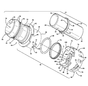
[0018] FIG. 1 is an exploded perspective view looking toward one side of a
quick connector assembly shown constructed in accordance with one aspect of
the invention;
[0019] FIG. 2A is an assembled isometric view of the quick connector
assembly components of FIG. 1;
[0020] FIG. 2B is an assembled partial isometric view of the quick
connector
assembly components of FIG. 1 with a shrink tube assembled thereabout;
[0021] FIG. 3 is a cross-sectional view of the quick connector assembly of
FIG. 2 with an insertion member shown in phantom therein;
[0022] FIG. 4A is a side isometric view of a retainer of the quick
connector of
FIG. 1;
[0023] FIG. 4B is a top isometric view of the retainer of the quick
connector of
FIG. 1;
[0024] FIG. 4C is a bottom isometric view of the retainer of the quick
connector of FIG. 1;
[0025] FIG. 4D is a side view of the retainer of the quick connector of
FIG. 1;
[0026] FIG. 4E is a fragmentary top view of the retainer of the quick
connector
of FIG. 1; and
[0027] FIG. 5 is a side isometric view of a housing of the quick connector
assembly of FIG. 1.
8
CA 2972605 2017-07-06
DETAILED DESCRIPTION OF PRESENTLY PREFERRED EMBODIMENTS
[0028] Referring
in general to all of the Figures, the present disclosure and
teachings described herein are directed to quick connectors and assemblies
therewith, of the type particularly well-suited for providing a fluid/gas
tight
connection (union) between conduits. While disclosed in accordance with one or
more specific exemplary constructions, a quick connector 10 and assembly 12
therewith, of the present disclosure, may be configured other than as
expressly
shown and described. The inventive concepts disclosed herein are generally
directed to an improved mechanism for forming and ensuring a fixed and
permanent (without breaking at least one of the components), reliable,
fluid/gas-
tight connection is made between a tubular male insertion member 14 and a
tubular receiving member, also referred to as housing 16, of the connector 10
via
an intermediate annular retainer, also referred to as retaining member 18, of
the
connector 10. The improved quick connector 10 and assembly 12 form a
reliable, fluid/gas-tight connection in such a manner as to do away with the
need
for costly sensor mechanisms to ensure and indicate the connection is made and
maintained, as a result of the permanent connection established by the
connector
(barring breaking or destroying one or more of the components). The
connector 10 is economical in manufacture, in assembly and in use, and
provides
a quick, reliable way in which to ensure a fluid/gas-tight connection is
established
between conduits and will be maintained between the male insertion member 14
and the housing 16, with reassurance that any potential of inadvertent
disconnection therebetween and tampering thereof is avoided.
9
CA 2972605 2017-07-06
[0029] During assembly, the retaining member 18 is disposed axially along a
central longitudinal axis A of the assembly 10, which corresponds to a central
longitudinal axis of the individual components 14, 16, 18, about an outer
surface
20 of a generally cylindrical, generally tubular wall 22 of the housing 16.
Upon
disposing the retaining member 18 onto and about the housing 16, the retaining
member 18 becomes automatically and permanently fixed thereon as a result of
interlocking features, discussed in more detail below. Then, the insertion
member 14 is inserted along the longitudinal axis A into a through bore 24 of
the
housing 14, which is bounded by an inner surface 25 of the housing 14,
whereupon the insertion member 14 is brought to a fully assembled state,
whereupon a fluid/gas-tight seal is perfected between the insertion member 14
and the housing 16. When full assembly has occurred between the insertion
member 14 and the housing 16, the locking features of the insertion member 14
and retaining member 18 operatively cooperate with one another to lockingly
engage the insertion member 14 with the housing 16. Upon being locked
together, assurance is provided that the fluid/gas-tight connection
therebetween
will be maintained between the insertion member 14 and the housing 16 over the
course of the useful life of the assembly 12 without having to employ costly
sensor mechanisms in communication with a vehicle control unit, and the like.
Accordingly, the connector 10 and assembly 12 therewith are cost efficient in
assembly and in use.
[0030] The insertion member 14 includes a tubular shaft portion 26 that
extends between opposite ends, with one end being an insertion end 28 and the
CA 2972605 2017-07-06
opposite end being an attachment end 30, with the attachment end 30 being
configured for operable attachment to a conduit (not shown). The insertion end
28 is shown as having a radiused lead-in surface in the form of a generally
rounded nose 32 that generally tapers or reduces in diameter to the insertion
end
28. The insertion member 12 further includes an assembly feature in the form
of
a collar, shown as being a circumferentially continuous annular collar 34,
between the opposite ends 28, 30. The annular collar 34 extends radially
outwardly from a generally cylindrical outer surface of the shaft portion 26
and is
shown as being generally rectilinear in cross-section. The annular collar 34
has
a radially outwardly extending, annular leading shoulder 36 and a radially
outwardly extending, annular trailing shoulder 38 spaced from one another by
an
outer periphery 40 (FIG. 1). The leading shoulder 36 is shown as merging with
the outer periphery 40 via a slightly rounded annular profile or corner 42,
such
that the corner 42 transitions the leading shoulder 36 in smooth arcuate
fashion
with the outer periphery. In contrast, the trailing shoulder 38 and the outer
periphery 40 are shown as merging with one another at a generally sharp or
square corner 44. The insertion member 12, as described, is a male conduit
member and may be constructed from any desired material known in the art,
including plastics, metals, or otherwise, wherein the insertion member 12 in
one
exemplary embodiment is a resinous tube.
[0031] The
housing 14, as best shown in FIGS. 1, 2A, 3 and 5, includes the
wall 22 having an enlarged diameter first cylindrical receiving portion 46, a
reduced diameter second cylindrical portion 48, with a stepped intermediate
11
CA 2972605 2017-07-06
diameter third cylindrical portion 50 extending between the first and second
cylindrical portions 46, 48, wherein an annular upper shoulder 51 (FIG. 3)
separates the upper first cylindrical receiving portion 46 from the
intermediate
third cylindrical portion 50 and an annular lower shoulder 53 separates the
lower
second cylindrical portion 48 from the intermediate third cylindrical portion
50. As
such, the relative diameters are such that the first diameter is greater than
the
second and third diameter, and the third diameter is greater than the second
diameter: D1>D3>02.
[0032] The wall
22 forms an end nipple portion, also referred to as coupling
portion 54, shown as having a plurality of consecutive annular ridges 56 along
its
outer periphery for operable attachment to a conduit 55 (FIG. 3) and an 0-ring
57
to facilitate forming a fluid-tight seal with the mating conduit. The enlarged
diameter receiving portion 46 extends to an open end 58, with the cylindrical
wall
22 thereof having at least one, and shown as a plurality (three, by way of
example and without limitation) of circumferentially spaced, locking openings
60
extending therethrough. The locking openings 60 are shown as being
equidistantly spaced from one another, though it is anticipated that other
spatial
relationships are possible, and have opposite flat or substantially flat sides
61
extending in generally parallel relation with one another. The housing 16
further
includes an annular flange 62 extending radially outwardly from the outer
surface
20. The annular flange 62 is shown as extending outwardly from the region of
the outer surface 20 where the receiving portion 46 transitions to the
intermediate
portion 50, wherein the locking openings 60 are formed between the flange 62
12
CA 2972605 2017-07-06
and the open end 58. The flange 62 has at least one notch, and shown as a
plurality of notches 66 therein, wherein the notches 66 are shown as being
spaced equidistantly from one another, by way of example and without
limitation.
[0033] The bore of the receiving portion 46 is sized diametrically to
receive at
least one elastomeric annular seal member, shown as an elastomeric 0-ring 68,
wherein the 0-ring 68 is shown as being seated against the upper shoulder 51
with an annular cylindrical spacer sleeve 70 being seated there against. It
should
be recognized the seal member could be configured other than as described and
shown, as long a fluid-tight seal is formed thereby against the tubular shaft
portion 26 of the insertion member 14 upon assembly and while in use.
[0034] The retaining member 16, as best shown in FIGS. 1, 2A, 3 and 4A-4D,
includes a generally annular, tubular retainer wall, and shown as a generally
cylindrical wall 72, having an inner surface 74 and an outer surface 76. The
inner
surface 74 of the wall 72 defines a bore, also referred to as through opening
77,
sized for close fitting receipt about at least a portion of the outer surface
20 of the
housing 16. The inner and outer surfaces 74, 76 extend axially along the
central
longitudinal axis A between open proximal and distal ends 78, 80. The retainer
wall 72 has at least one locking mechanism 81 provided via a locking member,
and shown as three locking members 82, by way of example and without
limitation, cantilevered by a corresponding number of resilient, elongate arms
84
fixed to the retainer wall 72. The elongate arms 84 and/or locking members 82
extend radially inwardly of the inner surface 74 a predetermined extent. As
such,
the locking members 82 are biased radially inwardly through the locking
openings
13
CA 2972605 2017-07-06
60 of the housing 16 upon assembly to deploy the locking members 82 radially
inwardly from the inner surface 25 of the tubular wall 22 forming the
receiving
portion 46. With the locking openings 60 being axially spaced from the upper
shoulder 51, the locking members 82 in turn are axially spaced from the upper
shoulder 51 by a gap G sized for captured receipt of the 0-ring 68, spacer 70,
and annular collar 34 of the tubular male insertion member 14 upon assembly,
wherein the locking members 82 are restrained against substantial axial and
rotational movement within their corresponding locking openings 60 due to a
close fit therein to prevent removal of the locking members 82 from the
locking
opening 60. The elongate arms 84 are formed being arcuate, as a monolithic
piece of material with the cylindrical wall 72, such as in a molding process,
by
way of example and without limitation. The arms 84 are hingedly supported by a
hinge or hinge-like connection 86 to the wall 72, wherein the arms 84 arch
from
the hinge connection 86 to the locking members 82 that extend radially
inwardly
a sufficient amount to extend radially inwardly from the inner surface of the
housing wall 22 upon assembly thereto, as discussed above.
[0035] The
locking members 82 have opposite radially facing surfaces 88,
opposite axially facing surfaces 90, 91 facing the proximal and distal ends
78, 80,
respectively, and opposite sides 92 extending between the opposite radially
facing surfaces 88 and the opposite axially facing surfaces 90, 91. The
opposite
sides 92 are flat or substantially flat, radially extending surfaces
configured in
parallel or substantially parallel relation with one another and in parallel
or
substantially parallel relation with the substantially flat sides 61 of the
opening 60.
14
CA 2972605 2017-07-06
As such, any relative torsional movement between the locking members 82 and
the openings 60 causes the sides 92 of the locking members 82 to confront and
lockingly abut the sides 61 of the locking openings 60, whereupon the sides
92,
61 act as stop surfaces, such that the locking members 82 remain fully
retained
within the locking openings 60 to prevent substantial relative rotation
between the
housing 16 and the retaining member 18.
[0036] As best shown in FIG. 4E, the axially facing surface 90 of the
locking
member 82 facing the proximal end 78 of the retaining member 18 has a radially
outwardly facing first inclined surface 94 and a radially inwardly facing
second
inclined surface 96. The first and second inclined surfaces 94, 96 converge
toward the proximal end 78 of the retaining member 18. The axially facing
surface 91 of the locking member 82 facing the distal end 80 of the retaining
member 18 is substantially flat, extending generally transversely to the
central
longitudinal axis A. To facilitate reducing the weight of the connector 10,
the wall
72 can be formed having at least one, and shown as a plurality of windows,
also
referred to as cutout regions 98. In the embodiment shown, a pair of cutout
regions is formed between each of the locking members 82.
[0037] The retaining member 18 further includes an anti-rotation feature,
provided as at least one tab, and shown as a plurality of tabs 100. The tabs
100
extend axially from the distal end 80 of the retaining member 18 for receipt
in the
notches 66 to prevent substantial relative rotation between the housing 16 and
the retaining member 18. Accordingly, the tabs 100 provide an anti-rotation
mechanism in combination with the locking members 82. It is contemplated that
CA 2972605 2017-07-06
the tabs 100 can be sized relative to the notches 66 to provide the bulk or
majority of anti-rotation, with the tolerances between the tabs 100 and the
notches 66 providing a relatively snug fit, thus, acting to minimize the
amount of
torsion placed on the locking members 82, though being capable of withstanding
torque to prevent relative rotation and removal of the locking members 82 from
the locking openings 60.
[0038] As shown
in FIG. 2B, upon coupling and fixing the retaining member
18 about the housing 16, with the locking members 82 being disposed and fixed
in the locking openings 60, a protective sleeve 102 can be disposed about the
retaining member 18 to cover the outer surface 76 the retaining member 18. The
protective sleeve 102 provides a backup assurance that the locking members 82
remain in their "as locked" positions, locked against the collar 34 of the
insertion
member 14, thereby blocking the insertion member 14 against removal from the
housing 16. It is to be recognized that in order for the protective sleeve 102
to
perform its backup function, it only need cover the locking mechanism 81, and
thus, it need not cover the entirety of the retaining member 18, though shown
as
extending over the entirety of the retaining member 18 and about the flange 62
of
the housing 16. By extending over the flange 62, the sleeve 102 is provided
with
added retention, thereby acting to provide additional assurance that sleeve
102
remains fixed over the locking mechanism 81, thus, further preventing radially
outward movement of the arms 84 and locking members 82 fixed thereto. It is to
be understood that the sleeve 102 can be provided of the desired snug fitting
material, and in one exemplary embodiment, the sleeve 102 was provided as a
16
CA 2972605 2017-07-06
heat-shrink tubular material, thereby allowing the sleeve 102 to be readily
disposed about the retaining member 18 and the flange 62, and then be
subsequently heated, thereby causing the sleeve 102 to constrict in shrinking
fashion into a snug, fixed fit as shown. Aside from the sleeve 102 function to
prevent the locking mechanism 81 from moving out of locked engagement with
the collar 34, the sleeve 102 also functions as a tamper-resistant member to
prevent disassembly of the insertion member 14 from the housing 16 without
breaking or destroying one of the components of the assembly 12. Accordingly,
visual evidence will exist indicating tampering if the "as assembled"
components
become disconnected from one another.
[0039] In assembly, with the 0-ring 68 and spacer sleeve 70 disposed
against
the upper shoulder 51, the retaining member 18 is disposed axially onto and
about the receiving portion 46 of the housing 16 along the longitudinal
central
axis A. Upon reaching the assembled state, the locking mechanism 81 snaps into
the locked state, whereupon the elongate, resilient arms 84 bias the locking
members 82 radially inwardly through the locking openings 60 and radially
inwardly of the inner surface 25 of the housing 16 (FIG. 3). With the
retaining
member 18 fixed to the housing 16, the protective sleeve 102 can be disposed
and fixed in position about the locking mechanism 81 and optionally about the
flange 62 for added retention, as discussed above.
[0040] With the retaining member 18 locked about the housing 16, the
insertion member 14 is disposed axially along the axis A into the housing 16.
The insertion end 28 of the male insertion member 14 is inserted into the
housing
17
CA 2972605 2017-07-06
16 until the leading shoulder 36 of the annular collar 34 engages the beveled
cam edge formed by the radially inwardly facing second inclined surface 96 of
the
locking member 82 to spring bias the locking member 82 resiliently and
slightly
radially outwardly from the male insertion member 14, thus allowing the
annular
collar 34 to pass axially beyond the locking member 82 into the gap G between
the locking member 82 and upper shoulder 51 of the housing 16. Upon the collar
34 fully clearing and passing beyond the locking member 82, the locking member
82 automatically snaps audibly and resiliently radially inwardly to return to
its
unbiased or substantially unbiased position, as biased by the elongate
resilient
arm 84 when deflected radially outwardly, to rest in the gap G.
[0041] With the
collar 34 received in the gap G, the radially inwardly facing
surface 88 of the locking member rests against the shaft portion 26 of the
male
insertion member 14 or is in close proximity thereto and the axially facing
surfaces 90, 91 rest in close proximity or against the trailing shoulder 38 of
the
collar 34 and the upper shoulder 51 of the housing 16. With the locking member
82 properly positioned immediately adjacent the trailing shoulder 38 of the
collar
34, the insertion member 14 is prevented from moving axially outwardly from
the
housing 16, and therefore the male insertion member 14 is fixedly locked
inside
the housing 16 with a fluid/gas-tight sealed connection established
therebetween.
If any axially applied force is applied between the insertion member 14 and
the
housing 16, tending to move the insertion member 14 outwardly from the housing
16, the radially outwardly facing first inclined surface 94 of the locking
member 82
is brought into camming engagement with a flat or generally flat, radially
18
CA 2972605 2017-07-06
extending surface 104 of the locking opening 60, whereupon the locking member
82 is caused to be driven further radially inwardly into an increased locked
position. Accordingly, reassurance is provided that the locked connection is
maintained between the insertion member 14 and the housing 16, even under
axially applied forces tending to move the insertion member 14 outwardly from
the housing 16.
[0042] Further
prevention of inadvertent, unwanted removal of the locking
members 82 from the locking openings 60 is provided under torsion and relative
twisting rotation between the housing 16 and the retaining member 18 as a
result
of the opposite sides 92 of the locking members 82 being flat or substantially
flat,
radially extending surfaces in close proximity with the flat or substantially
flat
sides 61 of the locking opening 60. The opposite sides 92 of the locking
members 82 and the opposite sides 61 of the locking openings 60 are parallel
or
substantially parallel with one another, extending in a radial direction, and
thus, if
they come into abutment with one another, they act as mutual stop surfaces
against one another, thereby preventing further relative rotation between the
housing 16 and the retaining member 18. Of course, as discussed above, the
tabs 100 and notches 66 in which the tabs 100 are received also function to
prevent relative rotation between the housing 16 and the retaining member 18.
Accordingly, upon connecting the insertion member 14 into the connector 10 to
form the assembly 12, the insertion member 14 is assured of being in proper
liquid/gas-tight connection therein, and is further prevented from inadvertent
removal and is further prevented from tampering. As such, upon completing the
19
CA 2972605 2017-07-06
assembly 12 as discussed and shown, no additional assurances, such as
sensors and the like, are needed to ensure the connection is made and
maintained.
[0043] The
foregoing description of the embodiments has been provided for
purposes of illustration and description. It is not intended to be exhaustive
or to
limit the disclosure or claims. Individual elements or features of a
particular
embodiment are generally not limited to that particular embodiment, but, where
applicable, are interchangeable and can be used in a selected embodiment, even
if not specifically shown or described. The same may also be varied in many
ways. Such variations are not to be regarded as a departure from the
disclosure,
and all such modifications are intended to be included within the scope of the
disclosure and claims, wherein the claims ultimately define the scope of the
invention.
CA 2972605 2017-07-06