Note: Descriptions are shown in the official language in which they were submitted.
CA 02972701 2017-06-28
WO 2016/109048 PCT/US2015/061430
SYSTEMS AND METHODS FOR APPLYING REDUCED PRESSURE THERAPY
BACKGROUND
Field
[00011 Embodiments of the present disclosure relate to methods and
apparatuses
for dressing and treating a wound with reduced pressure therapy or topical
negative pressure
(TNP) therapy. In particular, but without limitation, embodiments disclosed
herein relate to
negative pressure therapy devices, methods for controlling the operation of
TNP systems,
and methods of using TNP systems.
Description of the Related Art
[00021 Many different types of wound dressings are known for aiding in
the
healing process of a human or animal. These different types of wound dressings
include
many different types of materials and layers, for example, gauze, pads, foam
pads or multi-
layer wound dressings. Topical negative pressure (TNP) therapy, som.etimes
referred to as
vacuum assisted closure, negative pressure wound therapy, or reduced pressure
wound
therapy, is widely recognized as a beneficial mechanism for improving the
healing rate of a
wound. Such therapy is applicable to a broad range of wounds such as
incisional wounds,
open wounds and abdominal wounds or the like.
[00031 TNP therapy assists in the closure and healing of wounds by
reducing
tissue oedema, encouraging blood flow, stimulating the formation of
granulation tissue,
removing excess exudates and m.ay reduce bacterial load and, thus, infection
to the wound.
Furthermore, TNP therapy permits less outside disturbance of the wound and
promotes more
rapid healing.
SUMMARY
[00041 in some embodiments, an apparatus for applying negative pressure
therapy is disclosed. The apparatus includes a housing and a controller. The
housing
includes a source of negative pressure. The source of negative pressure
includes a pump
configured to be in fluidic communication with a wound dressing via a fluid
flow path. The
controller is configured to operate the source of negative pressure. In
addition, the controller
-1-
CA 02972701 2017-06-28
WO 2016/109048 PCT/US2015/061430
is configured to (i) determine a level of activity of the pump, (ii) detect
presence of a
blockage in the fluid flow path using the level of activity of the pump and
without using a
pressure in the fluid flow path, and (iii) in response to detecting presence
of the blockage in
the fluid flow path, provide an indication of the blockage in the fluid flow
path.
[00051 The apparatus of the preceding paragraph can include one or more
of the
following features: The controller is configured to determine the level of
activity of the
pump using a signal from a tachometer, and the signal is indicative of an
operation of a
motor of the pump. The controller is configured to (i) maintain a value in a
memory
responsive to the signal, the value being saturated when the level of activity
of the pump is at
or below a threshold level of activity and (ii) detect the presence of the
blockage in response
to determining that the value is saturated. The controller is configured to
detect the presence
of the blockage in response to determining that the value is saturated for a
duration of time.
The controller is configured to maintain the value in the memory by
periodically adjusting
the value responsive to the signal. The tachometer is external to the pump.
The controller is
configured to determine the level of activity of the pump from a duration of
time between at
least two consecutive pulses of the signal. The controller is configured to
detect the presence
of the blockage in response to determining that the duration of time between
the at least two
consecutive pulses satisfies a condition indicative of a blockage. The
condition is a blockage
threshold, and the controller is further configured to detect the presence of
the blockage in
response to determining that the duration of time between the at least two
consecutive pulses
exceeds the blockage threshold. The controller is configured to determine the
level of
activity of the pump from a duration of time between consecutive rising edges
of the signal
or consecutive falling edges of the signal. The controller is configured to
(i) determine
durations of time between at least two pulses of the signal and (ii) determine
the level of
activity of the pump from the determined durations of time. The controller is
configured to
(1) determine a variance of time between at least three pulses of the signal
and (ii) determine
the level of activity of the pump using the determined variance of time. The
controller is
configured to determine the level of activity of the pump from a change in a
period of pulses
of the signal. The controller is configured to (i) count a number of pulses of
the signal for
which a duration of time between consecutive pulses of the signal satisfies a
condition and
(ii) determine the level of activity of the pump according to the count. The
condition is a
-2-
CA 02972701 2017-06-28
WO 2016/109048 PCT/US2015/061430
threshold, and the controller is configured to count the number of pulses of
the signal for
which the duration of time between consecutive pulses of the signal exceeds
the threshold.
The controller is configured to detect the presence of the blockage from a
comparison of (i) a
distribution pattern indicative of a blockage and (ii) a distribution of
pulses of the signal over
a period of time or a number of the pulses of the signal. The tachometer
includes a Hall
effect sensor. The controller is configured to detect the presence of the
blockage in response
to determining that the level of activity of the pump is indicative of an
increased instability in
operation of a motor of the pump. The controller is configured to detect the
level of activity
without using measurements output by the pump. The controller is configured to
determine
the level of activity of the pump using a signal from a tachometer internal to
the pump, and
the signal is an encoded motor signal indicative of motion of a motor of the
pump. The
controller is configured to determine the level of activity of the pump from a
pulse width
modulated signal used to drive a motor of the pump. The controller is
configured to
determine the level of activity of the pump from indications of use of a motor
of the pump.
The controller is configured to detect the presence of the blockage further
using a change in
the level of activity of the pump. The apparatus further includes a flow
control valve
disposed between the pump and either an inlet or outlet of the housing, and
the flow control
valve is configured to permit fluid flow through the flow control valve in
only one direction.
A flow control valve is not disposed between the pump and either an inlet or
outlet of the
housing. The indication of the blockage includes an alarm, and the controller
is configured
to activate the alarm in response to detecting presence of the blockage in the
fluid flow path.
The apparatus further includes a canister configured to collect fluid
aspirated from under the
wound dressing, and the blockage in the fluid flow path includes the canister
being
substantially full. The level of activity of the pump includes an operating
speed of a pump
motor. The apparatus further includes the wound dressing configured to be
placed over a
wound.
10006j In some embodiments, a method of operating the apparatus of any
of the
preceding two paragraphs is disclosed.
-3-
CA 02972701 2017-06-28
WO 2016/109048 PCT/US2015/061430
BRIEF DESCRIPTION OF THE DRAWINGS
[00071 Embodiments of the present disclosure will now be described
hereinafter,
by way of example only, with reference to the accompanying drawings in which:
[00081 Figure 1 illustrates a reduced pressure wound therapy system
according to
some embodiments.
100091 Figures 2A-2C illustrate a pump assembly and canister according
to some
embodiments.
[00101 Figures 3A-3C illustrate block diagrams of components of a pump
assembly according to some embodiments.
[00111 Figure 4 illustrates a process of providing an indication of a
blockage
according to some embodiments.
100121 Figures 5A-5C show plots illustrating when a level of activity
of a pump
may be indicative a blockage according to some embodiments.
[00131 Figure 6 shows a plot illustrating the impact of a flow control
value in a
fluid flow path according to some embodiments.
100141 Figure 7 shows a plot illustrating the impact of a flow control
value in
various positions in a fluid flow path according to some embodiments.
[00151 Figures 8A-8B and 9A-9B show example plots illustrating when a
level of
activity of a pump may be indicative a blockage according to some embodiments.
DETAILED DESCRIPTION OF SOME EMBODIMENTS
Overview
[00161 Embodiments disclosed herein relate to systems and methods of
treating a
wound with reduced pressure. As is used herein, reduced or negative pressure
levels, such as
¨X mmHg, represent pressure levels relative to normal ambient atmospheric
pressure, which
can correspond to 760 mmHg (or 1 atm. 29.93 inHg, 101.325 kPa, 14.696 psi,
etc.).
Accordingly, a negative pressure value of ¨X mmHg reflects relative pressure
that is X
mmHg below 760 mmHg or, in other words, an absolute pressure of (760¨X) mmHg.
In
addition, negative pressure that is "less" or "smaller" than X mmHg
corresponds to pressure
that is closer to atmospheric pressure (e.g., ¨40 mmHg is less than ¨60 mmHg).
Negative
pressure that is "more" or "greater" than ¨X mmHg corresponds to pressure that
is further
-4-
CA 02972701 2017-06-28
WO 2016/109048 PCT/US2015/061430
from atmospheric pressure (e.g., ---80 mmHg is more than ---60 mmHg). In some
embodiments, local ambient atmospheric pressure is used as a reference point,
and such local
atmospheric pressure may not necessarily be, for example, 760 mmHg.
[00171 Embodiments of the present disclosure are generally applicable
to use in
topical negative pressure (TNP) or reduced pressure therapy systems. Briefly,
negative
pressure wound therapy assists in the closure and healing of many forms of
"hard to heal"
wounds by reducing tissue oedema, encouraging blood flow and granular tissue
formation, or
removing excess exudate and can reduce bacterial load (and thus infection
risk). In addition,
the therapy allows for less disturbance of a wound leading to more rapid
healing. TNP
therapy systems can also assist in the healing of surgically closed wounds by
removing fluid.
In some embodiments, TNP therapy helps to stabilize the tissue in the apposed
position of
closure. A further beneficial use of TNP therapy can be found in grafts and
flaps where
removal of excess fluid is important and close proximity of the graft to
tissue is required in
order to ensure tissue viability.
Negative Pressure System
[00181 Figure 1 illustrates an embodiment of a negative or reduced
pressure
wound treatment (or TNP) system 100 comprising a wound filler 130 placed
inside a wound
cavity 110, the wound cavity sealed by a wound cover 120. The wound filler 130
in
combination with the wound cover 120 can be referred to as wound dressing. A
single or
multi lumen tube or conduit 140 is connected the wound cover 120 with a pump
assembly
150 configured to supply reduced pressure. The wound cover 120 can be in
fluidic
communication with the wound cavity 110. In any of the system embodiments
disclosed
herein, as in the embodiment illustrated in Figure 1, the pump assembly can be
a canisterless
pump assembly (meaning that exudate is collected in the wound dressing or is
transferred via
tube 140 for collection to another location). However, any of the pump
assembly
embodiments disclosed herein can be configured to include or support a
canister.
Additionally, in any of the system embodiments disclosed herein, any of the
pump assembly
embodiments can be mounted to or supported by the dressing, or adjacent to the
dressing.
The wound filler 130 can be any suitable type, such as hydrophilic or
hydrophobic foam,
gauze, inflatable bag, and so on. The wound filler 130 can be conformable to
the wound
-5-
CA 02972701 2017-06-28
WO 2016/109048 PCT/US2015/061430
cavity 110 such that it substantially fills the cavity. The wound cover 120
can provide a
substantially fluid impermeable seal over the wound cavity 110. The wound
cover 120 can
have a top side and a bottom side, and the bottom side adhesively (or in any
other suitable
manner) seals with wound cavity 110. The conduit 140 or lumen or any other
conduit or
lumen disclosed herein can be formed from polyurethane, PVC, nylon,
polyethylene,
silicone, or any other suitable material.
[00191 Some embodiments of the wound cover 120 can have a port (not
shown)
configured to receive an end of the conduit 140. In other embodiments, the
conduit 140 can
otherwise pass through or under the wound cover 120 to supply reduced pressure
to the
wound cavity 110 so as to maintain a desired level of reduced pressure in the
wound cavity.
The conduit 140 can be any suitable article configured to provide at least a
substantially
sealed fluid flow pathway between the pump assembly 150 and the wound cover
120, so as
to supply the reduced pressure provided by the pump assembly 150 to wound
cavity 110.
[00201 The wound cover 120 and the wound filler 130 can be provided as
a single
article or an integrated single unit. In some embodiments, no wound filler is
provided and
the wound cover by itself may be considered the wound dressing. The wound
dressing may
then be connected, via the conduit 140, to a source of negative pressure, such
as the pump
assembly 150. The pump assembly 150 can be miniaturized and portable, although
larger
conventional pumps can also be used.
[00211 The wound cover 120 can be located over a wound site to be
treated. The
wound cover 120 can form a substantially sealed cavity or enclosure over the
wound site. In
some embodiments, the wound cover 120 can be configured to have a film having
a high
water vapour permeability to enable the evaporation of surplus fluid, and can
have a
superabsorbing material contained therein to safely absorb wound exudate. It
will be
appreciated that throughout this specification reference is made to a wound.
In this sense it
is to be understood that the term wound is to be broadly construed and
encompasses open
and closed wounds in which skin is torn, cut or punctured or where trauma
causes a
contusion, or any other surficial or other conditions or imperfections on the
skin of a patient
or otherwise that benefit from reduced pressure treatment. A wound is thus
broadly defined
as any damaged region of tissue where fluid may or may not be produced.
Examples of such
wounds include, but are not limited to, acute wounds, chronic wounds, surgical
incisions and
-6-
CA 02972701 2017-06-28
WO 2016/109048 PCT/US2015/061430
other incisions, subacute and dehisced wounds, traumatic wounds, flaps and
skin grafts,
lacerations, abrasions, contusions, burns, diabetic ulcers, pressure ulcers,
stoma, surgical
wounds, trauma and venous ulcers or the like. The components of the TNP system
described
herein can be particularly suited for incisional wounds that exude a small
amount of wound
exudate.
[00221 Some embodiments of the system are designed to operate without
the use
of an exudate canister. Some embodiments can be configured to support an
exudate
canister. In some embodiments, configuring the pump assembly 150 and conduit
140 so that
the conduit 140 can be quickly and easily removed from the pump assembly 150
can
facilitate or improve the process of dressing or pump changes, if necessary.
Any of the pump
embodiments disclosed herein can be configured to have any suitable connection
between the
tubing and the pump.
[00231 In some embodiments, the pump assembly 150 can be configured to
deliver negative pressure of approximately -80 mmHg, or between about -20 mmHg
and -200
mmHg. Note that these pressures are relative to normal ambient atmospheric
pressure thus,
-200 mmHg would be about 560 mmHg in practical terms. The pressure range can
be
between about -40 mmHg and -150 mmHg. Alternatively, a pressure range of up to
-75
mmHg, up to -80 mmHg or over -80 mmHg can be used. Also, a pressure range of
below -
75 mmHg can be used. Alternatively, a pressure range of over approximately -
100 mmHg,
or even 150 mmHg, can be supplied by the pump assembly 150.
[00241 in some embodiments, the pump assembly 150 is configured to
provide
continuous or intermittent negative pressure therapy. Continuous therapy can
be delivered at
above -25 mmHg, -25 mmHg, -40 mmHg, -50 mmHg, -60 mmHg, -70 mmHg, -80 mmHg,
-90 mmHg, -100 mmHg, -120 mmHg, -140 mmHg, -160 mmHg, -180 mmHg, -200 mmHg,
or below -200 mmHg. Intermittent therapy can be delivered between low and high
negative
pressure setpoints. Low setpoint can be set at above 0 mmHg, 0 mmHg, -25 mmHg,
-40
mmHg, -50 mmHg, -60 mmHg, -70 mmHg, -80 mmHg, -90 mmHg, -100 mmHg, -120
mmHg, -140 mmHg, -160 mmHg, -180 mmHg, or below -180 mmHg. High setpoint can
be
set at above -25 mmHg, -40 mmHg, -50 mmHg, -60 mmHg, -70 mmHg, -80 mmHg, -90
mmHg, -100 mmHg, -120 mmHg, -140 mmHg, -160 mmHg, -180 mmHg, -200 mmHg, or
below -200 mmHg. During intermittent therapy, negative pressure at low
setpoint can be
-7-
CA 02972701 2017-06-28
WO 2016/109048 PCT/US2015/061430
delivered for a first time duration, and upon expiration of the first time
duration, negative
pressure at high setpoint can be delivered for a second time duration. Upon
expiration of the
second time duration, negative pressure at low setpoint can be delivered. The
first and
second time durations can be same or different values. The first and second
durations can be
selected from the following range: less than 2 minutes, 2 minutes, 3 minutes,
4 minutes, 6
minutes, 8 minutes, 10 minutes, or greater than 10 minutes. In some
embodiments, switching
between low and high setpoints and vice versa can be performed according to a
step
waveform, square waveform, sinusoidal waveform, and the like.
[00251 In operation, the wound filler 130 is inserted into the wound
cavity 110
and wound cover 120 is placed so as to seal the wound cavity 110. The pump
assembly 150
provides a source of a negative pressure to the wound cover 120, which is
transmitted to the
wound cavity 110 via the wound filler 130. Fluid (e.g., wound exudate) is
drawn through the
conduit 140, and can be stored in a canister. In some embodiments, fluid is
absorbed by the
wound filler 130 or one or more absorbent layers (not shown).
[00261 Wound dressings that may be utilized with the pump assembly and
other
embodiments of the present application include Renasys-F, Renasys-G, Renasys
AB, and
Pico Dressings available from Smith & Nephew. Further description of such
wound
dressings and other components of a negative pressure wound therapy system
that may be
used with the pump assembly and other embodiments of the present application
are found in
U.S. Patent Publication Nos. 2011/0213287, 2011/0282309, 2012/0116334,
2012/0136325,
and 2013/0110058, which are incorporated by reference in their entirety. In
other
embodiments, other suitable wound dressings can be utilized.
Pump Assembly and Canister
[00271 Figure 2A illustrates a front view 200A of a pump assembly 230,
such as
the pump assembly 150, and canister 220 according to some embodiments. As is
illustrated,
the pump assembly 230 and the canister 220 are connected, thereby forming a
device. The
pump assembly 230 comprises one or more indicators, such as visual indicator
202
configured to indicate alarms and visual indicator 204 configured to indicate
status of the
TNP system. The indicators 202 and 204 can be configured to alert a user, such
as patient or
medical care provider, to a variety of operating or failure conditions of the
system, including
-8-
CA 02972701 2017-06-28
WO 2016/109048 PCT/US2015/061430
alerting the user to normal or proper operating conditions, pump failure,
power supplied to
the pump or power failure, detection of a leak within the wound cover or flow
pathway,
suction blockage, or any other similar or suitable conditions or combinations
thereof. The
pump assembly 230 can comprise additional indicators. The pump assembly can
use a single
indicator or multiple indicators. Any suitable indicator can be used such as
visual, audio,
tactile indicator, and so on. The indicator 202 can be configured to signal
alarm conditions,
such as canister full, power low, conduit 140 disconnected, seal broken in the
wound seal
120, and so on. The indicator 202 can be configured to display red flashing
light to draw a
user's attention. The indicator 204 can be configured to signal status of the
TNP system,
such as therapy delivery is ok, leak detected, and so on. The indicator 204
can be configured
to display one or more different colors of light, such as green, yellow, etc.
For example,
green light can be emitted when the TNP system is operating properly and
yellow light can
be emitted to indicate a warning.
[00281 The pump assembly 230 comprises a display or screen 206 mounted
in a
recess 208 formed in a case of the pump assembly. The display 206 can be a
touch screen
display. The display 206 can support playback of audiovisual (AV) content,
such as
instructional videos. As explained below, the display 206 can be configured to
render a
number of screens or graphical user interfaces (GUIs) for configuring,
controlling, and
monitoring the operation of the TNP system. The pump assembly 230 comprises a
gripping
portion 210 formed in the case of the pump assembly. The gripping portion 210
can be
configured to assist the user to hold the pump assembly 230, such as during
removal of the
canister 220. The canister 220 can be replaced with another canister, such as
when the
canister 220 has been filled with fluid.
[00291 The pump assembly 230 comprises one or more keys or buttons 212
configured to allow the user to operate and monitor the operation of the TNP
system. As is
illustrated, there buttons 212a, 212b, and 212c are included. Button 212a can
be configured
as a power button to turn on/off the pump assembly 230. Button 212b can be
configured as a
play/pause button for the delivery of negative pressure therapy. For example,
pressing the
button 212b can cause therapy to start, and pressing the button 212b afterward
can cause
therapy to pause or end. Button 212c can be configured to lock the display 206
or the
buttons 212. For instance, button 212c can be pressed so that the user does
not
-9-
CA 02972701 2017-06-28
WO 2016/109048 PCT/US2015/061430
unintentionally alter the delivery of the therapy. Button 212c can he
depressed to unlock the
controls. In other embodiments, additional buttons can be used or one or more
of the
illustrated buttons 212a, 212b, or 212c can be omitted. Multiple key presses
or sequences of
key presses can be used to operate the pump assembly 230.
[00301 The pump assembly 230 includes one or more latch recesses 222
formed
in the cover. In the illustrated embodiment, two latch recesses 222 can be
formed on the
sides of the pump assembly 230. The latch recesses 222 can be configured to
allow
attachment and detachment of the canister 220 using one or more canister
latches 221. The
pump assembly 230 comprises an air outlet 224 for allowing air removed from
the wound
cavity 110 to escape. Air entering the pump assembly can be passed through one
or more
suitable filters, such as antibacterial filters. This can maintain reusability
of the pump
assembly. The pump assembly 230 includes one or more strap mounts 226 for
connecting a
carry strap to the pump assembly 230 or for attaching a cradle. In the
illustrated
embodiment, two strap mounts 226 can be formed on the sides of the pump
assembly 230. In
some embodiments, various of these features are omitted or various additional
features are
added to the pump assembly 230.
[00311 The canister 220 is configured to hold fluid (e.g., exudate)
removed from
the wound cavity 110. The canister 220 includes one or more latches 221 for
attaching the
canister to the pump assembly 230. In the illustrated embodiment, the canister
220
comprises two latches 221 on the sides of the canister. The exterior of the
canister 220 can
formed from frosted plastic so that the canister is substantially opaque and
the contents of the
canister and substantially hidden from plain view. The canister 220 comprises
a gripping
portion 214 formed in a case of the canister. The gripping portion 214 can be
configured to
allow the user to hold the pump assembly 220, such as during removal of the
canister from
the apparatus 230. The canister 220 includes a substantially transparent
window 216, which
can also include graduations of volume. For example, the illustrated 300 mL
canister 220
includes graduations of 50 mLõ 100 mL, 150 mL, 200 miõ 250 mL, and 300 mL.
Other
embodiments of the canister can hold different volume of fluid and can include
different
graduation scale. For example, the canister can be an 800 mL canister. The
canister 220
comprises a tubing channel 218 for connecting to the conduit 140. In some
embodiments,
various of these features, such as the gripping portion 214, are omitted or
various additional
-10-
CA 02972701 2017-06-28
WO 2016/109048 PCT/US2015/061430
features are added to the canister 220. Any of the disclosed canisters may
include or may
omit a solidifier.
[00321 Figure 2B illustrates a rear view 200B of the pump assembly 230
and
canister 220 according to some embodiments. The pump assembly 230 comprises a
speaker
port 232 for producing sound. The pump assembly 230 includes a filter access
door 234 for
accessing and replacing one or more filters, such as antibacterial filters.
The pump assembly
230 comprises a gripping portion 236 formed in the case of the pump assembly
230. The
gripping portion 236 can be configured to allow the user to hold the pump
assembly 230,
such as during removal of the canister 220. The pump assembly 230 includes one
or more
covers 238 configured to as screw covers or feet or protectors for placing the
pump assembly
230 on a surface. The covers 230 can be formed out of rubber, silicone, or any
other suitable
material. The pump assembly 230 comprises a power jack 239 for charging and
recharging
an internal battery of the pump assembly. The power jack 239 can be a direct
current (DC)
jack. In some embodiments, the pump assembly 230 can comprise a disposable
power
source, such as batteries, so that no power jack is needed.
[00331 The canister 220 includes one or more feet 244 for placing the
canister on
a surface. The feet 244 can be formed out of rubber, silicone, or any other
suitable material
and can be angled at a suitable angle so that the canister 220 remains stable
when placed on
the surface. The canister 220 comprises a tube mount relief 246 configured to
allow one or
more tubes to exit to the front of the device. The canister 220 includes a
stand or kickstand
248 for supporting the canister when it is placed on a surface. As explained
below, the
kickstand 248 can pivot between an opened and closed position. In closed
position, the
kickstand 248 can be latched to the canister 220. In some embodiments, the
kickstand 248
can be made out of opaque material, such as plastic. In other embodiments, the
kickstand
248 can be made out of transparent material. The kickstand 248 includes a
gripping portion
242 formed in the kickstand. The gripping portion 242 can be configured to
allow the user to
place the kickstand 248 in the closed position. The kickstand 248 comprises a
hole 249 to
allow the user to place the kickstand in the open position. The hole 249 can
be sized to allow
the user to extend the kickstand using a finger.
[00341 Figure 2C illustrates a view 200C of the pump assembly 230
separated
from the canister 220 according to some embodiments. The pump assembly 230
includes a
-I I-
CA 02972701 2017-06-28
WO 2016/109048 PCT/US2015/061430
vacuum attachment, connector, or inlet 252 through which a vacuum pump
communicates
negative pressure to the canister 220. The pump assembly aspirates fluid, such
as gas, from
the wound via the inlet 252. The pump assembly 230 comprises a USB access door
256
configured to allow access to one or more USB ports. In some embodiments, the
USB access
door is omitted and USB ports are accessed through the door 234. The pump
assembly 230
can include additional access doors configured to allow access to additional
serial, parallel,
or hybrid data transfer interfaces, such as SD, Compact Disc (CD), DVD,
FireWire,
Thunderbolt, PC! Express, and the like. In other embodiments, one or more of
these
additional ports are accessed through the door 234.
[00351 Additional description of the pump assembly 230 is disclosed in
U.S.
Patent Publication No. 2015/0025482, which is incorporated by reference in its
entirety.
Pump Assembly Components
[00361 Figure 3A illustrates a block diagram of certain components 300A
of a
pump assembly, such as the pump assembly 150, according to some embodiments.
The
components 300A include an inlet 310 (such as inlet 252), a flow control valve
320, a pump
330, an exhaust 340, a pressure sensor 350, and a pump controller 360.
[00371 The pump controller 360 can control the operation of the pump
330. The
pump 330 can provide negative pressure in a fluid flow path connecting the
inlet 310, the
flow control valve 320, and the pump 330 such that the negative pressure is
provided to the
inlet 310 and then to a wound (for example, through a canister). The pump 330
can be a
suitable pump, such as a diaphragm pump, peristaltic pump, rotary pump, rotary
vane pump,
scroll pump, screw pump, liquid ring pump, diaphragm pump operated by a
piezoelectric
transducer, voice coil pump, and the like. The flow control valve 320 can be a
valve, such as
a check valve like one commercially available from Value Plastics, Inc. or
Qosina, Corp.,
that permits fluid flow through the valve in only one direction. In the
illustration of Figure
3A, the flow control valve 320 can allow fluid to flow in the fluid flow path
from the inlet
310 to the exhaust 340, but not from the exhaust 340 to the inlet 310.
[00381 In some embodiments, the pump controller 360 can measure the
pressure
in the fluid flow path near or at the inlet 310 (or at any other location in
the fluid flow path,
such as at the wound), using data received from one or more pressure sensors,
such as the
-12-
CA 02972701 2017-06-28
WO 2016/109048 PCT/US2015/061430
pressure sensor 350, calculate the rate of fluid flow, and control the pump.
In some
embodiments, the pump controller 360 controls an actuator, such as a pump
motor of the
pump 330, so that a desired level of negative pressure is achieved in the
wound cavity 110.
The desired level of negative pressure (or negative pressure setpoint) can be
a pressure set or
selected by the user. In various embodiments, the pump controller 360 controls
the pump
330 using pulse-width modulation (PWM), such as by controlling the pump motor
of the
pump 330 using PWM. A control signal for driving the pump 330 can be a 0-100%
duty
cycle PWM signal. The pump controller 360 can perform flow rate calculations
and detect
alarm conditions. The pump controller 360 can include internal memory (not
shown) or
utilize external memory (not shown), and the pump controller 360 can be a low-
power
processor.
100391 In some embodiments, the pump controller 360 can, at least in
some
instances, control the pump 330, perform. flow rate calculations, or detect
alarm conditions
without measuring or using measurements of the pressure in the fluid flow path
or without
using measurements output by the pump 330 (such as, a signal from an internal
tachometer
of the pump 330 that is responsive to a rotation of a pump motor of the pump).
For example,
the pump controller 360 can, at least in some instances, control the pump 330,
perform flow
rate calculations, or detect alarm conditions by using at least or only a
level of activity of the
pump 330 and without measuring or using measured pressure in the fluid flow
path. As
another example, the pump controller 360 can control the pump 330, perform
flow rate
calculations, or detect alarm conditions using at least or only measurements
of the pressure in
the fluid flow path and without determining or using the determined level of
activity of the
pump. This can be performed, for instance, by comparing the magnitude of a
detected
pressure signal to one or more thresholds, such as a blockage threshold to
determine an
occlusion or blockage in the fluid flow path. One or more pulses detected or
sensed by the
pressure sensor can be determined as exceeding (or meeting or falling below)
the blockage
threshold. When the number of such pulses meets a threshold (such as exceeds,
becomes
equal to, or falls below), determination of a blockage can be made. Another
condition can be
that time between pulses that meet the blockage threshold. When such time
meets a
threshold (such as exceeds, becomes equal to, or falls below), determination
of a blockage
can be made. Using a level of activity of a pump to determine or estimate flow
may be in
-13-
CA 02972701 2017-06-28
WO 2016/109048 PCT/US2015/061430
contrast with direct measurement of flow rate, such as by using a flow meter.
In various
embodiments, determination of canister full, leakage, and the like can
additionally or
alternatively be made.
[00401 The components 300A can further include one or more additional
sensors
(not shown), such as a tachometer, positioned to detect or determine a level
of activity of the
pump 330 and provide indications responsive to the level of activity of the
pump 330 to the
pump controller 360. For example, a tachometer can be separate from the pump
330 (for
example, external to the pump) and positioned near or coupled to the pump 330,
and the
tachometer can detect a rotation (such as a partial rotation, complete
rotation, or multiple
partial or complete rotations) of a pump motor of the pump 330. The tachometer
can output
a signal (or signals) that provide the indications, such as pulses (for
example, high signal
indications in a series of otherwise low signal indications), responsive to
the rotation of the
pump motor to the pump controller 360. The tachometer can be a Hall effect
sensor or opto-
isolator sensor in some implementations.
[00411 The pump controller 360 can perform flow rate monitoring for the
fluid
flow path using the indications from the one or more additional sensors. The
pump
controller 360 can continuously or periodically monitor the indications from
the one or more
additional sensors to monitor the flow rate. For example, the pump controller
360 can
receive the signal including indications from a tachometer and thereby
determine a rotation
speed (sometimes referred to as an operating speed) of the pump motor of the
pump 330. If
the rotation speed may be below, at, or above a certain level, for instance,
it can be
determined that a blockage (sometimes referred to as a limited volume
condition) may be
present in the fluid flow path. The blockage can be due to a blockage in a
tube or lumen,
canister being full, etc. An alarm can be triggered by the pump controller 360
in such
instances, and the pump controller 360 can wait for a user to take one or more
actions to
resolve the blockage. In some embodiments, at least in some instances, the
pump controller
360 can control the pump, perform flow rate calculations, or detect alarm
conditions using
the indications responsive to the level of activity of the pump 330 and
without using
measurements of the pressure in the fluid flow path or without using
measurements output by
the pump 330.
-14-
CA 02972701 2017-06-28
WO 2016/109048 PCT/US2015/061430
[00421 Figure 3B illustrates a block diagram of certain components 300B
of a
pump assembly, such as the pump assembly 150, according to some embodiments.
The
components 300B can be the same as the components 300A of Figure 3A except
that the
position of the pump 330 and flow control valve 320 in the fluid flow path can
be switched.
Thus, the flow control valve 320 can be positioned on the exhaust-side of the
pump 330 in
the fluid flow path as illustrated in Figure 3B, rather than the inlet-side of
the pump 330 in
the fluid flow path as illustrated in Figure 3A.
[00431 Figure 3C illustrates a block diagram of components 300C of a
pump
assembly, such as the pump assembly 150, according to some embodiments. The
components 300C can be the same as the components 300A of Figure 3A except
that the
flow control valve 320 may not be included in the fluid flow path as
illustrated in Figure 3C.
In certain embodiments, a flow control valve can be integrated into the pump
330.
Blockage Detection
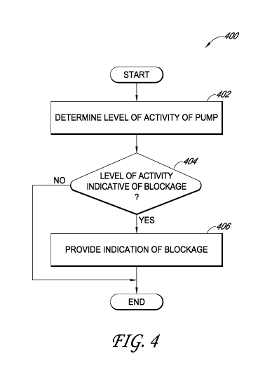
[00441 Figure 4 illustrates a process 400 of providing an indication of
a blockage
in a fluid flow path according to some embodiments. The process 400 can be
executed by
the pump controller 360, for example. The process 400 can be continuously or
periodically
executed or at any other suitable frequency. Advantageously, in certain
embodiments, the
process 400 can enable an indication of a blockage in a fluid flow path to be
provided
without using the pressure in the fluid flow path or without using
measurements output by
the pump to detect the blockage.
[00451 At block 402, the process 400 can determine a level of activity
of a pump,
such as the pump 330. The level of activity of the pump can be determined
continuously or
periodically or at any other suitable frequency. in one example, the level of
activity of the
pump can be determined according to a level of activity of a pump motor of the
pump that is
detected by a sensor, such as a tachometer. The tachometer can detect a
rotation of the pump
motor and provide a signal including indications, such as pulses, responsive
to the rotation.
In another example, the level of activity of the pump can be determined using
a PWM signal
used to drive the pump motor, an encoded signal output by the pump, or the
pressure in the
fluid flow path. In certain embodiments, one or more of these or other
determinations can be
combined to calculate the level of activity.
-15-
CA 02972701 2017-06-28
WO 2016/109048 PCT/US2015/061430
[00461 In some embodiments, the level of activity of the pump can be
determined
using a signal (for example, a signal output by a tachometer) by determining
if one or more
conditions have been met or satisfied. In some embodiments, one or more of the
following
can be determined: (1) a duration of time between consecutive features of the
signal, (2)
multiple durations of time between multiple features of the signal, (3) a
variance of time
between features of the signal (for example, average period), (4) a count of a
number of
features of the signal for which a duration of time between consecutive
features of the signal
exceeds (or meets or falls below) a threshold value, and (5) a range of time
between features
of the signal. The features (sometimes referred to as pulses) of the signal
can be, for
instance, one or more of a rising edge of the signal, a falling edge of the
signal, a peak of the
signal, and a trough of the signal. In another example, the level of activity
of the pump can
be determined according to a PWM signal used to drive the pump motor or an
encoded motor
signal output by the pump. The process 400 can, in some embodiments, further
determine a
change in the level of activity of the pump over time at block 402. The change
in the level of
activity of the pump can be determined continuously or periodically or at any
other suitable
frequency. In some embodiments, the level of activity or change in the level
of activity can
be further processed, such as averaged, filtered, and the like.
[00471 At block 404, the process 400 can determine whether the level of
activity
of the pump is indicative of a blockage in a fluid flow path. The fluid flow
path can provide
for fluidic communication between a wound dressing, such as the wound cover
120, and the
pump, and the blockage can be a condition indicative of a substantially full
canister or
dressing or that a canister or dressing filter may be occluded or blocked. In
one example, the
level of activity of the pump can be indicative of the blockage when the level
or the change
in level of activity of the pump satisfies (for instance, meets, falls below,
or exceeds) one or
more thresholds or matches one or more patterns (such as (i) a certain number
of the last total
number of pulses of a signal exceed a limit, (ii) repeated long delays in
pulses of a signal
followed by a short delay in one or more pulses of the signal, or (iii) a
value tracked by a
processor, like the pump controller 360, and responsive to pulses of a signal
remains constant
or substantially constant (for instance, the signal become saturated because a
frequency in the
pulses of the signal is so low that data collection capabilities of the
sensor(s) or processor
prevent the processor from further adjusting the value)). In another example,
the level of
-16-
CA 02972701 2017-06-28
WO 2016/109048 PCT/US2015/061430
activity of the pump can be indicative of the blockage when the level of
activity shows an
increased instability in the operation of the pump. The increased instability
can, for instance,
be evidenced in pump control behavior when the pump repeatedly overshoots a
pump control
setpoint, decays from a pump control setpoint, or accelerates from a pump
control setpoint.
As another example, as explained herein, increased instability can be
manifested via unstable
levels of pump activity, such as when a variance of measured pump activity
meets (such as
exceeds or falls below) a threshold.
10048j Example levels of activity or changes in a level of activity of
a pump over
time that may be indicative or not indicative of the blockage are described at
least with
respect to Figures 5A-5C. Other example levels of activity or changes in the
level of activity
of the pump over time that may be indicative or not indicative of the blockage
will be
apparent from reviewing at least the described example levels or changes
described herein.
[00491 If the level of activity of the pump over time is not indicative
of the
blockage in the fluid flow path, the process 400 can end, or in some
embodiments, one or
more other checks can be performed using different approaches to determine
whether a
blockage is present. On the other hand, if the level of activity of the pump
over time is
indicative of the blockage in the fluid flow path, the process 400 can move to
block 406. At
block 406, the process 400 can provide an indication of the blockage. The
indication of the
blockage can, for example, include activating an alarm denoting the blockage.
The alarm
can, in turn, direct a user to investigate or resolve the blockage. In some
instances, the
indication of the blockage can denote a potential blockage condition rather
than definitively
indicating a blockage condition. In some embodiments, the process 400 can also
perform
one or more other checks using different approaches to confirm the presence of
a blockage.
In another example, the indication of the blockage can include changing an
operating mode
of the pump, such as deactivating the pump, triggering a countdown timer for
deactivating
the pump if the blockage is not resolved within a period of time, or
increasing or decreasing
the level of activity of the pump.
100501 In certain embodiments, executing the process 400 can provide
one or
more different advantages. In one example, the process 400 can be desirable
for use with a
pump controller or pump that may be relatively cheap, simple, or have limited
capabilities.
This can be because the process 400 may use relatively straightforward
techniques (for
-17-
CA 02972701 2017-06-28
WO 2016/109048 PCT/US2015/061430
example, determining a duration of time between features of a signal, a
counting features of a
signal and then comparing the duration or count to a threshold, or detecting
saturation for a
period of time in a tracked value responsive to pulses of a signal) to
determine whether to
provide an indication of a blockage, and thus may be incorporated into a pump
controller or
pump that is relatively inexpensive and simple. In another example, using the
process 400
can be desirable because a pump assembly, such as the pump assembly 150, may
not include
a pressure sensor, such as the pressure sensor 350, to determine whether to
provide an
indication of a blockage or may not include a pump that outputs a signal
indicative of the
level of activity of the pump. As a result, the cost of the pump assembly can
be reduced, and
the size of the pump assembly may also be decreased. In yet another example,
using the
process 400 can be desirable for increasing the robustness or accuracy of
determining
whether to provide an indication of a blockage. The process 400 can, for
instance, be used in
combination with or independently from one or more other blockage
determinations (for
example, blockage determinations based on pressure measurements, weight
measurements,
or optical detection in a canister or a fluid flow path) to make a final
determination of
whether to provide an indication of a blockage. The process 400 can
additionally be
advantageous because the process 400 may detect a blockage when one or more
other
blockage determinations may fail to detect the blockage. For instance, when
other
processing (for example, averaging) may be performed on measurements from a
sensor
detecting the level of activity of a pump (for instance, an operating speed),
such processing
may smooth or mask a blockage from being noted from the processed signal,
while the
blockage may be readily detectable using the approaches provided herein. In
one illustration,
six tachometer pulses every 60 seconds may produce the same calculated average
as five
tachometer pulses respectively separated by 180 seconds, 20 seconds, 40
seconds, 60
seconds, and 60 seconds. However, the five tachometer pulses may be indicative
of a
blockage as described herein while the six tachometer pulses may not be
indicative of a
blockage. In some embodiments, the process 400 can distinguish between various
types of
blockage conditions, such as between canister (or dressing) full and blockage
in other
portions of the flow path.
10051j Figure SA shows an example plot 500A illustrating when a level
of
activity of a pump, such as the pump 330, may be indicative a blockage
according to some
-18-
CA 02972701 2017-06-28
WO 2016/109048 PCT/US2015/061430
embodiments. The plot 500A can be a plot for a pump assembly, such as the pump
assembly
230, which includes the components 300A, 300B, or 300C discussed with respect
to Figures
3A-3C, as well as a tachometer configured to provide pulses indicative of a
rotation of a
pump motor of the pump. The y-axis of the plot 500A provides a time between
consecutive
tachometer pulses in seconds, and the x-axis of the plot 500A provides an
assigned
numbering for approximately 450 consecutive tachometer pulses. Curve 502A
illustrates data
obtained for a flow path that does not have a blockage, and curve 504A
illustrates data
obtained from a flow path with a blockage.
[00521 The plot 500A illustrates, for instance, how a longer duration
between
tachometer pulses or consecutive tachometer pulses can be indicative of a
blockage, such as
a full canister (or dressing). Based on the plot 500A, as one example, a
threshold can be set
such that when a time between consecutive tachometer pulses exceeds about 2
seconds, the
level of activity of the pump can be considered indicative of a blockage. As
another
example, the threshold can be set to about 3 seconds, 4 seconds, etc.
[00531 Figure 5B shows an example plot 500B illustrating when a level
of
activity of a pump, such as the pump 330, may be indicative a blockage
according to some
embodiments. The plot 500B can be a plot for a pump assembly, such as the pump
assembly
230, which includes the components 300A, 300B, or 300C discussed with respect
to Figures
3A-3C, as well as a tachometer configured to provide pulses indicative of a
rotation of a
pump motor of the pump. The y-axis of the plot 500B provides a time between
consecutive
tachometer pulses in seconds, and the x-axis of the plot 500B provides an
assigned
numbering for approximately 50 consecutive tachometer pulses (as opposed to
about 450
pulses in Figure 5A) . Curve 502B illustrates data obtained for a flow path
that does not
have a blockage, and curve 504B illustrates data obtained from a flow path
with a blockage.
10054j The plot 500B illustrates, for instance, how a longer duration
between
consecutive tachometer pulses can be indicative of a blockage, such as a full
canister (or
dressing) condition. Based on the plot 500B, as one example, a threshold can
be set such that
when a time between consecutive tachometer pulses exceeds about I second, the
level of
activity of the pump can be considered indicative of a blockage. As another
example, the
threshold can be set to about 2 seconds, 3 seconds, etc.
-19-
CA 02972701 2017-06-28
WO 2016/109048 PCT/US2015/061430
[00551 Figure 5C shows an example plot 500C illustrating when a level
of
activity of a pump may be indicative a blockage according to some embodiments.
The plot
500C can be a plot for a pump assembly, such as the pump assembly 230, which
includes the
components 300A, 300B, or 300C discussed with respect to Figures 3A-3C, as
well as a
tachometer configured to provide pulses indicative of a rotation of a pump
motor of the
pump. The y-axis of the plot 500C provides a minimum observed time between
tachometer
pulses in seconds, and the x-axis of the plot 500C shows a restricting
canister condition or
empty canister condition. Curve 502C illustrates data obtained for a flow path
that does not
have a blockage, and curve 504C illustrates data obtained from a flow path
with a blockage.
[00561 The plot 500C illustrates, for instance, how a longer duration
between
minimum observed times between tachometer pulses or consecutive tachometer
pulses can
be indicative of a blockage, such as a canister (or dressing) full canister.
Based on the plot
500C, as one example, a threshold can be set such that when a minimum observed
time
between consecutive tachometer pulses exceeds 2 seconds, the level of activity
of the pump
can be considered indicative of a blockage. As another example, the threshold
can be set to
about 3 seconds, 4 seconds, etc.
100571 Figure 6 shows an example plot 600 illustrating the impact of a
flow
control value in a fluid flow path on a detected signal usable to determine a
level of activity
of a pump according to some embodiments. The plot 600 can be a plot for a pump
assembly,
such as the pump assembly 230, which includes the components 300A or 300B in
the case of
the flow control valve line and the components 300C in the case of the no flow
control valve
line, as well as a tachometer configured to provide pulses indicative of a
rotation of a pump
motor of the pump. The y-axis of the plot 600 provides a time between
consecutive
tachometer pulses in seconds, and the x-axis of the plot 600 provides an
assigned numbering
for approximately 850 consecutive tachometer pulses. Curve 602 illustrates
data obtained
for a pump assembly without a flow control valve, and curve 604 illustrates
data obtained for
a pump assembly with a flow control valve. The plot 600 further depicts moving
averages
for the curves 602, 604 that can be processed in addition to or in place of
the curves 602, 604
in some embodiments.
[00581 The plot 600, for instance, illustrates how, in certain
embodiments, the
inclusion of the flow control valve in the fluid flow path can result in more
stable pump
-20-
CA 02972701 2017-06-28
WO 2016/109048 PCT/US2015/061430
activity and, in turn, more stable or accurate measurements from a sensor,
such as a
tachometer, positioned to detect or determine the level of activity of the
pump. Moreover, in
addition to the flow direction control benefits of the flow control valve, the
flow control
valve can reduce pressure waves in the fluid flow path by providing a pressure
drop and
functioning as a low-pass filter for pressure signals traveling to the pump.
The inclusion of
the flow control valve can further help with preventing nuisance to user
caused by spurious
activation of pump assembly alarms. In various embodiments, duration between
non-
consecutive pulses can be utilized. In some embodiments, measure of variance
of the level
of activity of the pump, such as an average tachometer period, can be used in
addition to or
instead of duration between features of the level of activity, such as
duration between
consecutive tachometer pulses. This is described in connection with Figures 8A-
8B and 9A-
9B, for example.
[00591 Figure 7 shows an example plot 700 illustrating the impact of a
flow
control value in various positions in a fluid flow path on a detected signal
usable to
determine a level of activity of a pump according to some embodiments. The
plot 700 can be
a plot for a pump assembly, such as the pump assembly 230, which includes the
arrangement
of the components 300A in the case of the inlet-side valve line 704, the
arrangement of the
components 300B in the case of the exhaust-side valve line 706, and the
components 300C in
the case of the no flow control valve line 702, as well as a tachometer
configured to provide
pulses indicative of a rotation of a pump motor of the pump. The y-axis of the
plot 700
provides a pressure sensor voltage for a pressure sensor, such as the pressure
sensor 350, and
the x-axis of the plot 700 provides time.
[00601 The plot 700, for instance, illustrates how, in certain
embodiments, the
inclusion of the flow control valve in the fluid flow path can result in
attenuated or reduced
pressure waves (for example, by providing a pressure drop and functioning as a
low-pass
filter for pressure signals traveling to the sensor). As is illustrated by
curve 704, which
corresponds to the arrangement of the components 300A of Figure 3A, inclusion
of a flow
control valve at the inlet can advantageously reduce pressure waves and result
in more
accurate, stable, greater signal amplitude measurements from one or more
sensors, such as a
an activity sensor (for example, a tachometer), than other arrangements or
combinations of
components. As is explained in connection with Figures 8A-8B and 9A-8B, this
can provide
-21-
CA 02972701 2017-06-28
WO 2016/109048 PCT/US2015/061430
for improved discrimination during processing of the sensed signal. The
inclusion of the
flow control valve can further help with preventing nuisance to user caused by
spurious
activation of pump assembly alarms.
Blockage Detection Using Clamped State Detection
[00611 Figure 8A shows an example plot 800A illustrating when a level
of
activity of a pump, such as the pump 330, may be indicative of a blockage
according to some
embodiments. The plot 800A can be a plot for a pump assembly, such as the pump
assembly
230, which includes the components 300C discussed with respect to Figure 3C,
as well as a
tachometer configured to provide pulses indicative of a rotation of a pump
motor of the
pump. The pump assembly can be operating at a setpoint of -40 mmHg. The y-axis
of the
plot 800A provides an average time period (or frequency) between consecutive
tachometer
pulses in seconds (scale on the left), mass flow measure in standard liter per
minute (SI,PM)
(scale on the right), and scaled alarm indication (high corresponds to "ON").
The x-axis of
the plot 800A provides elapsed time in minutes. The plot 800A depicts an
average
tachometer period 802, a blockage threshold setting 804, a mass flow
measurement 806 (for
example, flow rate directly measured using a flow meter, such as a mass flow
meter), and a
scaled alarm 808 over time. The scaled alarm 808 can be indicative of an alarm
condition,
such as a blockage condition, when high. The scaled alarm. 808 can, for
instance, (1) be used
to activate and deactivate an alarm, which can. be audibly or visually
perceptible, (ii) be an
alarm flag in memory, or (iii) involve or trigger changing operation of the
pump.
[00621 The plot 800A illustrates, for instance, how the scaled alarm
808 may not
be activated when the average tachometer period 802 does not satisfy the
blockage threshold
804. As can be seen, the average tachometer period 802 remains below the
blockage
threshold 804 such that the scaled alarm 808 remains deactivated. However, the
mass flow
measurement 806 illustrates little to no flow in the fluid flow path, which is
indicative of a
blockage condition.
[00631 Figure 8B shows an example plot 800B illustrating when a level
of
activity of a pump, such as the pump 330, may be indicative a blockage
according to some
embodiments. The plot 800B can be a plot for a pump assembly, such as the pump
assembly
230, which includes the components 300A discussed with respect to Figure 3A,
as well as a
-22-
CA 02972701 2017-06-28
WO 2016/109048 PCT/US2015/061430
tachometer configured to provide pulses indicative of a rotation of a pump
motor of the
pump. The pump assembly can be operating at a setpoint of -40 mmHg. The y-axis
of the
plot 800B provides an average time period between consecutive tachometer
pulses in
seconds (scale on the left), mass flow measure in SLPM (scale on the right),
and scaled alarm
indication (high corresponds to "ON"). The x-axis of the plot 800B provides
elapsed time in
minutes. The plot 800B depicts an average tachometer period 812, a blockage
threshold
setting 814, a clamped state threshold 815, a mass flow measurement 816, and a
scaled alarm
818 over time. The scaled alarm 818 can be indicative of an alarm condition,
such as a
blockage condition, when high. The scaled alarm 818 can, for instance, (i) be
used to
activate and deactivate an alarm, which can be audibly or visually
perceptible, (ii) be an
alarm flag in memory, or (iii) involve or trigger changing operation of the
pump. In
comparison with the average tachometer period 802 of Figure 8A (which is
obtained from a
pump that does not include a fluid control valve), the average tachometer
period 812 has
larger, more accurate amplitude or dynamic range, so that accuracies of
processing and
detection are improved. In some embodiments, period of time between
consecutive
tachometer pulses (such as for example in Figures 5A-5C and 6) or any other
measure of the
level of activity can be utilized instead of or in addition to the average
tachometer period.
[00641 The plot 800B illustrates, for instance, how the scaled alarm
818 may be
activated when the average tachometer period 812 satisfies at least one of the
blockage
threshold setting 814 or the clamped state threshold setting 815
instantaneously or for a
period of time (for example, 10 seconds, 20 seconds, 30 seconds, 45 seconds, 1
minute, 1.5
minutes, 2 minutes, 3 minutes, etc.). As can be seen, the scaled alarm 818 may
not be
activated at around 4 minutes because the average tachometer period 812 may
not have
satisfied the blockage threshold setting 814 or the clamped state threshold
setting 815. On
the other hand, the scaled alarm 818 can be activated at around 12 minutes and
17 minutes
when the average tachometer period 812 satisfies the blockage threshold
setting 814.
Activation of the scaled alarm 818 at around 12 minutes and 17 minutes can
thus be used to
trigger a blockage threshold alarm. The scaled alarm 818 activated at around
12 minutes and
17 minutes can be deactivated at around 14 minutes and 18 minutes when the
average
tachometer period 812 may no longer satisfy the blockage threshold setting
814. In addition,
the scaled alarm 818 may be activated at around 23 minutes when the average
tachometer
-23-
CA 02972701 2017-06-28
WO 2016/109048 PCT/US2015/061430
period 812 satisfies the clamped state threshold setting 815. Activation of
the scaled alarm
818 at around 23 minutes can thus be used to trigger a clamped state threshold
alarm. The
scaled alarm 818 activated at around 23 minutes can be deactivated at around
32 minutes
when the average tachometer period 812 may no longer satisfy one or both of
the blockage
threshold setting 814 or the clamped state threshold setting 815. This
operation can be
confirmed by the mass flow measurement 816, which illustrates little to no
flow in the fluid
flow path, which is indicative of a blockage condition. Moreover, the mass
flow
measurement 816 at around between 0-10 minutes and around between 30-40
minutes can
represent a minimum allowable flow for a pump assembly. As a result, an alarm
during
around between 0-10 minutes and around between 30-40 minutes can be considered
a
nuisance alarm. In addition, the mass flow measurement 816 at around between
10-30
minutes and around between 40-60 minutes can be less than the minimum
allowable flow for
the pump assembly, so an alarm. may be expected and triggered as described
herein. After an
alarm is triggered, the mass flow measurement 816 can return to the minimum
allowable
state, and the alarm can be then cleared as illustrated at around 31 minutes.
[00651 Clamped state detection can be performed using the clamped state
threshold setting 815, which can be a threshold for the pump that depends on
the data
collection capabilities of the pump. The pump can track a value, such as the
average
tachometer period 812 (or count of tachometer pulses and the like), responsive
to the level of
activity of the pump. In some instances, however, because the pump may be
operating
slowly due to a blockage in a flow path (for instance, pump motor may be
turning slowly),
sensed indication of the pump activity may become unreliable. For example, the
time
between tachometer pulses may become so long due to the blockage so that it
meets a
threshold (for instance, exceed or fall below the threshold) that corresponds
to a cut off for
collecting meaningful data. This condition may be referred to as recording a
saturated value
or reaching a "clamped state." Clamped state may be reached for various
reasons, including,
for example, due to one or more sensors or a pump controller (for instance,
the pump
controller 360) of the pump being relatively cheap, simple, or having limited
capabilities (for
instance, processing speed, memory, etc.). In clamped state, the determined
value
corresponding to the level of activity may saturate and remain constant for a
period of time
because the value may be unable to be further increased or decreased (in other
words, the
-24-
CA 02972701 2017-06-28
WO 2016/109048 PCT/US2015/061430
value becomes saturated) even though the value should further change
responsive to the level
of activity of the pump according to the function which is used to adjust the
value.
Advantageously, in certain embodiments, the saturation of such a value can
provide an
indication of an irregular condition for the pump and a more reliable and
faster indication of
a blockage than some other approaches.
[00661 In one example, a pump controller of a pump may have a capacity
to track
a level of activity of the pump using a value stored using 8 bits of data
(this is, the level of
activity can be tracked with a granularity of 256 levels ranging from the
level 0 to the level
255) where the level 255 can be indicative of a lowest assigned level of
activity and the level
0 can be indicative of a highest assigned level of activity. In this example,
the level of
activity of the pump may drop below the lowest assigned level of activity and
thus the pump
controller may consider the level of activity to remain at the 255 level even
though the level
of activity has decreased below lowest assigned level of activity. Therefore,
when the value
remains at the 255 level and thus saturates, the saturation of the value can
indicate an
irregular operating condition for the pump and can be used as an alarm
condition indicative
of a blockage. In some embodiments, to prevent intermittent alarms, which may
be a
nuisance to the user, the saturation of the value may be considered an alarm
condition once
the value remains saturated for a period of time, such as 30 seconds, 1
minute, 2 minutes, and
the like.
[00671 In some embodiments, checking for the clamped state using a
clamped
state threshold results in more accurate and reliable blockage detection than
only using a
blockage threshold. This is because meeting the clamped threshold can reliably
indicate that
a pump is operating very slowly due to a permanent blockage in a fluid flow
path. In
contrast, relying on the blockage threshold alone may result in less stable
and accurate
detection at least because a pump controller may not differentiate between (i)
a temporary
blockage (which may become cleared and should not trigger a blockage alarm)
and (ii) a
permanent blockage in the fluid flow path. On the other hand, meeting the
clamped state
threshold, which is selected to signal a very low activity of the pump as
compared to the
blockage threshold, can indicate that a severe blockage is present and that
such blockage is
unlikely to be a temporary blockage. Accordingly, blockage condition may be
triggered
more accurately and reliably when the clamped state threshold is used.
Although the plot
-25-
CA 02972701 2017-06-28
WO 2016/109048 PCT/US2015/061430
800B illustrates simultaneous use of the blockage threshold 814 and the
clamped state
threshold 815, the blockage threshold 814 and the clamped state threshold 815
can each be
implemented independently or without one threshold or the other. In addition,
in some
embodiments, the scaled alarms 808 and 818 can be used, alone or in
combination, with one
or more other conditions or indications (for example, such as those disclosed
herein) to
determine whether to activate an alarm.
[00681 Figure 9A shows an example plot 900A illustrating when a level
of
activity of a pump, such as the pump 330, may be indicative a blockage
according to some
embodiments. The plot 900A can be a plot for a pump assembly, such as the pump
assembly
230, which includes the components 300C discussed with respect to Figure 3C,
as well as a
tachometer configured to provide pulses indicative of a rotation of a pump
motor of the
pump. The pump assembly can be operating at a setpoint of -120 mmHg. The y-
axis of the
plot 900A provides an average time period between consecutive tachometer
pulses in
seconds (scale on the left), mass flow measure in SLPM (scale on the right),
and scaled alarm
indication (high corresponds to "ON"). The x-axis of the plot 900A provides
elapsed time in
minutes. The plot 900A depicts an average tachometer period 902, a blockage
threshold
setting 904, a mass flow measurement 906, and a scaled alarm 908 over time.
The scaled
alarm 908 can be indicative of an alarm condition, such as a blockage
condition, when high.
The scaled alarm 908 can, for instance, (I) be used to activate and deactivate
an alarm, which
can be audibly or visually perceptible, (ii) be an alarm flag in memory, or
(iii) involve
changing operation of the pump.
10069j The plot 900A illustrates, for instance, how the scaled alarm
908 may not
activate when the average tachometer period 902 does not satisfy the blockage
threshold
setting 904. As can be seen, the average tachometer period 902 remains below
the blockage
threshold setting 904 such that the scaled alarm 908 remains deactivated.
However, the mass
flow measurement 906 illustrates little to no flow in the fluid flow path,
which is indicative
of a blockage condition.
100701 Figure 9B shows an example plot 900B illustrating when a level
of
activity of a pump, such as the pump 330, may be indicative a blockage
according to some
embodiments. The plot 900B can be a plot for a pump assembly, such as the pump
assembly
230, which includes the components 300A discussed with respect to Figure 3A,
as well as a
-26-
CA 02972701 2017-06-28
WO 2016/109048 PCT/US2015/061430
tachometer configured to provide pulses indicative of a rotation of a pump
motor of the
pump. The pump assembly can be operating at a setpoint of -120 mmHg. The y-
axis of the
plot 900B provides an average time period between consecutive tachometer
pulses in
seconds (scale on the left), mass flow measure in SLPM (scale on the right),
and scaled alarm
indication (high corresponds to "ON"). The x-axis of the plot 900B provides
elapsed time in
minutes. The plot 900B depicts an average tachometer period 912, a blockage
threshold
setting 914, a mass flow measurement 916, and a scaled alarm 918 over time.
The scaled
alarm 918 can be indicative of an alarm condition, such as a blockage
condition, when high.
The scaled alarm 918 can, for instance, (1) be used to activate and deactivate
an alarm, which
can be audibly or visually perceptible, (ii) be an alarm flag in memory, or
(iii) involve or
trigger changing operation of the pump. In comparison with the average
tachometer period
902 of Figure 9A (which is obtained from a pump that does not include a fluid
control valve),
the average tachometer period 912 has larger, more accurate amplitude or
dynamic range, so
that accuracies of processing and detection are improved.
[00711 A clamped state threshold is not illustrated in Figure 9B
because it is set at
an average tachometer period that exceeds the maximum value of 0.40 seconds on
the y-axis
(scale on the left). For example, in Figure 8B the clamped state threshold
setting 815 is set to
about 0.825 seconds. However, in some embodiments, because the negative
pressure
setpoint in Figure 9B is set to a larger value (-120 mmHg) than the setpoint
in Figure 8B (-40
mmHg), which causes the pump to have a higher level of activity (for example,
pump motor
to turn faster) to reach and maintain the lower negative pressure setpoint,
the average
tachometer period 912 is generally smaller than the average tachometer period
812.
Accordingly, selecting a clamped state threshold for Figure 9B to be same or
similar to the
clamped state threshold setting 815, which is selected for a lower negative
pressure setpoint,
may result in blockage detection relying only on the blockage threshold 914.
The plot 900B
illustrates, for instance, how the scaled alarm 918 may activate when the
average tachometer
period 912 satisfies the blockage threshold setting 914 instantaneously or for
a period of time
(for example, 10 seconds, 20 seconds, 30 seconds, 45 seconds, 1 minute, 1.5
minutes, 2
minutes, 3 minutes, etc.). As can be seen, the scaled alarm 918 can be
activated at around 12
minutes and 42 minutes when the average tachometer period 912 satisfies the
blockage
threshold setting 914 for the period of time. The scaled alarm 918 activated
at around 12
-27-
CA 02972701 2017-06-28
WO 2016/109048 PCT/US2015/061430
minutes and 42 minutes can thus be used to trigger a blockage threshold alarm.
The scaled
alarm 918 activated at around 12 minutes and 42 minutes can accordingly be
deactivated at
around 31 minutes when the average tachometer period 912 may no longer satisfy
the
blockage threshold setting 914.
[00721 By comparing the plots 800A and 8008 with the plots 900A and
900B, it
can be further seen that as the setpoint increases, it may be less likely for
an average
tachometer period to satisfy a clamped state threshold as the average
tachometer period may
be less likely to increase to the level of the clamped state threshold and
reach saturation. In
some embodiments, the clamped state threshold can be selected from a plurality
of clamped
state thresholds based at least on the negative pressure setpoint. For
example, as the negative
pressure setpoint increases, decreasing values of the clamped state threshold
can be selected.
Similar selection can be performed for the blockage threshold in various
embodiments.
Other Variations
[00731 Any value of a threshold, limit, duration, etc. provided herein
is not
intended to be absolute and, thereby, can be approximate. In addition, any
threshold, limit,
duration, etc. provided herein can be fixed or varied either automatically or
by a user.
Furthermore, as is used herein relative terminology such as exceeds, greater
than, less than,
etc. in relation to a reference value is intended to also encompass being
equal to the reference
value. For example, exceeding a reference value that is positive can encompass
being equal
to or greater than the reference value. In addition, as is used herein
relative terminology such
as exceeds, greater than, less than, etc. in relation to a reference value is
intended to also
encompass an inverse of the disclosed relationship, such as below, less than,
greater than,
etc. in relations to the reference value.
100741 Features, materials, characteristics, or groups described in
conjunction
with a particular aspect, embodiment, or example are to be understood to be
applicable to
any other aspect, embodiment or example described herein unless incompatible
therewith.
All of the features disclosed in this specification (including any
accompanying claims,
abstract and drawings), or all of the steps of any method or process so
disclosed, may be
combined in any combination, except combinations where at least some of such
features or
steps are mutually exclusive. The protection is not restricted to the details
of any foregoing
-28-
CA 02972701 2017-06-28
WO 2016/109048 PCT/US2015/061430
embodiments. The protection extends to any novel one, or any novel
combination, of the
features disclosed in this specification (including any accompanying claims,
abstract and
drawings), or to any novel one, or any novel combination, of the steps of any
method or
process so disclosed.
[00751 While certain embodiments have been described, these embodiments
have
been presented by way of example only, and are not intended to limit the scope
of protection.
Indeed, the novel methods and systems described herein may be embodied in a
variety of
other forms. Furthermore, various omissions, substitutions and changes in the
form of the
methods and systems described herein may be made. Those skilled in the art
will appreciate
that in some embodiments, the actual steps taken in the processes illustrated
or disclosed may
differ from those shown in the figures. Depending on the embodiment, certain
of the steps
described above may be removed, others may be added. For example, the actual
steps or
order of steps taken in the disclosed processes may differ from those shown in
the figure.
Depending on the embodiment, certain of the steps described above may be
removed, others
may be added. For instance, the various components illustrated in the figures
may be
implemented as software or firmware on a processor, controller, ASIC, FPGA, or
dedicated
hardware. Hardware components, such as processors, ASICs, FPGAs, and the like,
can
include logic circuitry. Furthermore, the features and attributes of the
specific embodiments
disclosed above may be combined in different ways to form additional
embodiments, all of
which fall within the scope of the present disclosure.
[00761 User interface screens illustrated and described herein can
include
additional or alternative components. These components can include menus,
lists, buttons,
text boxes, labels, radio buttons, scroll bars, sliders, checkboxes, combo
boxes, status bars,
dialog boxes, windows, and the like. User interface screens can include
additional or
alternative information. Components can be arranged, grouped, displayed in any
suitable
order.
[00771 Conditional language used herein, such as, among others, "can,"
"might,"
"may," "e.g.," and the like, unless specifically stated otherwise, or
otherwise understood
within the context as used, is generally intended to convey that certain
embodiments include,
while other embodiments do not include, certain features, elements or states.
Thus, such
conditional language is not generally intended to imply that features,
elements or states are in
-29-
CA 02972701 2017-06-28
WO 2016/109048 PCT/US2015/061430
any way required for one or more embodiments or that one or more embodiments
necessarily
include logic for deciding, with or without author input or prompting, whether
these features,
elements or states are included or are to be performed in any particular
embodiment. The
terms "comprising," "including," "having," and the like are synonymous and are
used
inclusively, in an open-ended fashion, and do not exclude additional elements,
features, acts,
operations, and so forth. Also, the term "or" is used in its inclusive sense
(and not in its
exclusive sense) so that when used, for example, to connect a list of
elements, the term "or"
means one, some, or all of the elements in the list. Further, the term "each,"
as used herein,
in addition to having its ordinary meaning, can mean any subset of a set of
elements to which
the term "each" is applied.
100781 Disjunctive language such as the phrase "at least one of X, Y
and Z,"
unless specifically stated otherwise, is to be understood with the context as
used in general to
convey that an item, term, etc. may be either X, Y, or Z, or a combination
thereof. Thus,
such conjunctive language is not generally intended to imply that certain
embodiments
require at least one of X, at least one of Y and at least one of Z to each be
present.
[00791 Unless otherwise explicitly stated, articles such as "a" or "an"
should
generally be interpreted to include one or more described items. Accordingly,
phrases such
as "a device configured to" are intended to include one or more recited
devices. Such one or
more recited devices can also be collectively configured to carry out the
stated recitations.
For example, "a processor configured to carry out recitations A, B and C" can
include a first
processor configured to carry out recitation A working in conjunction with a
second
processor configured to carry out recitations B and C.
[00801 Although the present disclosure includes certain embodiments,
examples
and applications, it will be understood by those skilled in the art that the
present disclosure
extends beyond the specifically disclosed embodiments to other alternative
embodiments or
uses and obvious modifications and equivalents thereof, including embodiments
which do
not provide all of the features and advantages set forth herein. Accordingly,
the scope of the
present disclosure is not intended to be limited by the specific disclosures
of preferred
embodiments herein, and may be defined by claims as presented herein or as
presented in the
future.
-30-