Note: Descriptions are shown in the official language in which they were submitted.
CA2972819
VAPOR ABLATION SYSTEMS AND METHODS
CROSS REFERENCE TO RELATED APPLICATIONS
[0001] This application claims the benefit of US Provisional Patent
Application No. 62/109,540,
filed January 29, 2015, titled "VAPOR ABLATION SYSTEMS AND METHODS".
[0002] <deleted>
FIELD
[0003] The present invention relates to devices and related methods for
treatment of benign
prostatic hyperplasia using a minimally invasive approach. More specifically,
the present disclosure
relates to treating benign prostatic hyperplasia with vapor delivered to the
prostate.
BACKGROUND
[0004] Benign prostatic hyperplasia (BPH) is a common disorder in middle-
aged and older men,
with prevalence increasing with age. At age 50, more than one-half of men have
symptomatic BPH, and
by age 70, nearly 90% of men have microscopic evidence of an enlarged
prostate. The severity of
symptoms also increase with age with 27% of patients in the 60-70 age bracket
having moderate-to-
severe symptoms, and 37% of patients in their 70's suffering from moderate-to-
severe symptoms.
[0005] The prostate early in life is the size and shape of a walnut and
prior to the enlargement
resulting from BPH, weighs about 20 grams. Prostate enlargement appears to be
a normal process.
With age, the prostate gradually increases in size to twice or more its normal
size. The fibromuscular
tissue of the outer prostatic capsule restricts expansion after the gland
reaches a certain size. Because of
such restriction on expansion, the intracapsular tissue will compress against
and constrict the prostatic
urethra, thus causing resistance to urine flow.
[0006] In the male urogenital anatomy, the prostate gland is located
below the bladder and the
bladder neck. The walls of the bladder can expand and contract to cause urine
flow through the urethra,
which extends from the bladder, through the prostate and penis. The portion of
urethra that is
surrounded by the prostate gland is referred to as the prostatic urethra. The
prostate also surrounds the
ejaculatory ducts which have an open termination in the prostatic
- 1 -
Date Recue/Date Received 2022-05-13
CA 02972819 2017-06-29
WO 2016/123498
PCT/US2016/015684
urethra. During sexual arousal, sperm is transported from the testes by the
ductus deferens to the
prostate which provides fluids that combine with sperm to form semen during
ejaculation. On
each side of the prostate, the ductus deferens and seminal vesicles join to
form a single tube
called an ejaculatory duct. Thus, each ejaculatory duct carries the seminal
vesicle secretions and
sperm into the prostatic urethra.
[0007] The prostate glandular structure can be classified into three
zones: the peripheral
zone, transition zone, and central zone. Peripheral zone PZ comprises about
70% of the volume
of a young man's prostate. This sub-capsular portion of the posterior aspect
of the prostate gland
surrounds the distal urethra and 70 to 80% of cancers originate in the
peripheral zone tissue. The
central zone CZ surrounds the ejaculatory ducts and contains about 20-25% of
the prostate
volume. The central zone is often the site of inflammatory processes. The
transition zone TZ is
the site in which benign prostatic hyperplasia develops, and contains about 5-
10% of the volume
of glandular elements in a normal prostate, but can constitute up to 80% of
such volume in cases
of BPH. The transition zone consists of two lateral prostate lobes and the
periurethral gland
region. There are natural barriers around the transition zone, i.e., the
prostatic urethra, the
anterior fibromuscular stroma, and a fibrous plane between the transition zone
and peripheral
zone. The anterior fibromuscular stroma or fibromuscular zone is predominantly
fibromuscular
tissue.
[00081 BPH is typically diagnosed when the patient seeks medical
treatment complaining of
bothersome urinary difficulties. The predominant symptoms of BPH are an
increase in
frequency and urgency of urination, and a significant decrease in the rate of
flow during
urination. BPH can also cause urinary retention in the bladder which in turn
can lead to lower
urinary tract infection (LUTI). In many cases, the LUTI then can ascend into
the kidneys and
cause chronic pyelonephritis, and can eventually lead to renal insufficiency.
BPH also may lead
to sexual dysfunction related to sleep disturbance or psychological anxiety
caused by severe
urinary difficulties. Thus, BPH can significantly alter the quality of life
with aging of the male
population.
[0009] BPH is the result of an imbalance between the continuous
production and natural
death (apoptosis) of the glandular cells of the prostate. The overproduction
of such cells leads to
increased prostate size, most significantly in the transition zone which
traverses the prostatic
urethra.
[00101 In early stage cases of BPH, pharmacological treatments can
alleviate some of the
symptoms. For example, alpha-blockers treat BPH by relaxing smooth muscle
tissue found in
the prostate and the bladder neck, which may allow urine to flow out of the
bladder more easily.
- 2 -
CA 02972819 2017-06-29
WO 2016/123498
PCT/US2016/015684
Such drugs can prove effective until the glandular elements cause overwhelming
cell growth in
the prostate.
[0011] More advanced stages of BPH, however, can only be treated by
surgical or less-
invasive thermal ablation device interventions. A number of methods have been
developed
using clectrosurgical or mechanical extraction of tissue, and thermal ablation
or cryoablation of
intracapsular prostatic tissue. In many cases, such interventions provide only
transient relief, and
these treatments often cause significant pen-operative discomfort and
morbidity.
[0012] In one thermal ablation method, RF energy is delivered to prostate
tissue via an
elongated RF needle being penetrated into a plurality of locations in a
prostate lobe. The
elongated RF needle is typically about 20 mm in length, together with an
insulator that
penetrates into the lobe. The resulting RF treatment thus ablates tissue away
from the prostatic
urethra and does not target tissue close to, and parallel to, the prostatic
urethra. The application
of RF energy typically extends for 1 to 3 minutes or longer which allows
thermal diffusion of the
RF energy to ablate tissue out to the capsule periphery. Such RF energy
delivery methods may
not create a durable effect, since smooth muscle tissue and alpha adrenergic
receptors are not
uniformly ablated around the prostatic urethra or within the transition zone.
As a result, tissue in
the prostate lobes can continue to grow and impinge on the urethra thus
limiting long-term
effectiveness of the treatment.
SUMMARY OF THE DISCLOSURE
[0013] A vapor delivery system is provided, comprising a generator unit
including a cradle, a
syringe assembly disposed in the cradle and configured to interact with the
cradle to deliver a
fluid at a controlled rate, an inductive heating system fluidly coupled to the
syringe assembly and
configured to receive fluid from the syringe assembly, a force sensor disposed
in the cradle and
configured contact the cradle and/or syringe assembly to generate an
electrical signal
proportional to a force exerted on the force sensor by the cradle and/or
syringe assembly, and an
electronic controller configured control delivery of fluid and RF power to the
inductive heating
system for the production of vapor, the electronic controller being further
configured to calibrate
the electrical signal as representing a fluid pressure within the syringe
assembly, the electronic
controller being further configured to stop delivery of fluid and/or RF power
to the inductive
heating system when the fluid pressure falls outside of a desired range of
fluid pressures.
[0014] In some embodiments, the cradle is arranged such that a distal end
of the syringe
assembly is held at a higher elevation than a proximal end of the syringe
assembly when the
syringe assembly is inserted into the cradle.
- 3 -
CA2972819
[0015] In one embodiment, the cradle is configured to purge any air from
the syringe assembly
during a priming procedure in which fluid is force from the syringe assembly
through the vapor delivery
system.
[0016] In another embodiment, the cradle further comprises a piston
coupled to a linear motor,
wherein the piston interacts with a plunger of the syringe assembly to
delivery fluid from the syringe
assembly.
[0017] In some embodiments, a contact switch is activated when the
syringe assembly is inserted
into the cradle.
[0018] In one embodiment, the inductive heating system comprises an inner
fluid coil surrounded by
an outer conductive coil.
[0019] A method of controlling a flow of vapor is provided, comprising
receiving a syringe
assembly into a cradle of a generator unit, delivering a fluid at a controlled
rate from the syringe
assembly to an inductive heating system fluidly coupled to the syringe
assembly, measuring a force
exerted on a force sensor that is disposed in the cradle and configured
contact the cradle and/or syringe
assembly during fluid delivery, and calibrating the measured force with an
electronic controller to
represent a fluid pressure within the syringe assembly, and stopping delivery
of fluid to the inductive
heating system when the fluid pressure falls outside of a desired range of
fluid pressures.
[0020] A method of treating prostate tissue is provided, comprising
inserting a vapor delivery
system transurethrally into a patient to access the prostatic urethra of the
patient, advancing a vapor
delivery needle generally transverse to the vapor delivery system through the
prostatic urethra and into a
transition zone of the prostate, and delivering vapor through distally facing
vapor delivery ports of the
vapor delivery needle to direct the vapor distally from the device into the
prostate.
10020A1 Various embodiments of the claimed invention relate to a vapor
delivery system, comprising:
a generator unit; a cradle disposed in the generator unit; a syringe assembly
disposed in the cradle and
.. configured to interact with the cradle to deliver a fluid at a controlled
rate, wherein a barrel of the
syringe assembly directly contacts the cradle; an inductive heating system
fluidly coupled to the syringe
assembly and configured to receive fluid from the syringe assembly; a force
sensor disposed in the
cradle and configured contact the cradle and/or the syringe assembly to
generate an electrical signal
proportional to a force exerted on the force sensor by the cradle and/or
syringe assembly; and an
electronic controller configured to control delivery of fluid and RF power to
the inductive heating
system for the production of vapor, to calibrate the electrical signal as
representing a fluid pressure
within the syringe assembly, and to stop delivery of fluid and/or the RF power
to the inductive heating
system when the fluid pressure falls outside of a predetermined range of fluid
pressures.
- 4 -
Date Recue/Date Received 2022-05-13
CA2972819
[0020B] Various embodiments of the claimed invention relate to a vapor
delivery system, comprising: a
generator unit; a cradle disposed in the generator unit; a syringe assembly
disposed in the cradle and
configured to interact with the cradle to deliver a fluid at a controlled
rate; an inductive heating system
fluidly coupled to the syringe assembly and configured to receive fluid from
the syringe assembly; a force
sensor disposed between the cradle and the generator and configured to
generate an electrical signal
proportional to a force exerted on the force sensor by the cradle; and an
electronic controller configured to
control delivery of fluid and RF power to the inductive heating system for the
production of vapor, to
calibrate the electrical signal as representing a fluid pressure within the
syringe assembly, and to stop
delivery of the fluid and/or the RF power to the inductive heating system when
the fluid pressure falls
outside of a predetermined range of fluid pressures.
[0020C] Various embodiments of the claimed invention relate to a vapor
delivery system, comprising: a
generator unit; a cradle disposed in the generator unit; a syringe assembly
disposed in the cradle and
configured to interact with the cradle to deliver a fluid at a controlled
rate; an inductive heating system
fluidly coupled to the syringe assembly and configured to receive fluid from
the syringe assembly; a force
sensor disposed in the cradle and configured to contact the cradle and/or the
syringe assembly to generate
an electrical signal proportional to a lateral force exerted on the force
sensor by the cradle and/or the
syringe assembly in a lateral direction, wherein the lateral direction is a
direction perpendicular to a
longitudinal axis of the syringe assembly; and an electronic controller
configured to control delivery of
fluid and RF power to the inductive heating system for the production of
vapor, to calibrate the electrical
signal as representing a fluid pressure within the syringe assembly, and to
stop delivery of the fluid and/or
the RF power to the inductive heating system when the fluid pressure falls
outside of a predetermined
range of fluid pressures.
[0020D] Various embodiments of the claimed invention relate to a vapor
delivery system, comprising:
a generator unit; a cradle disposed in the generator unit; a syringe assembly
disposed in the cradle so
that a barrel of the syringe assembly directly contacts the cradle; a force
sensor disposed in the cradle
and configured to contact the cradle and/or the syringe assembly, wherein the
force sensor is
configured to generate an electrical signal indicative of a force exerted on
the force sensor by the
cradle and/or the syringe assembly; and an electronic controller configured to
receive the electrical
signal, wherein the electronic controller is configured to calibrate the
electrical signal to represent a
pressure of fluid within the syringe assembly.
[0020E] Various embodiments of the claimed invention relate to a vapor
delivery system, comprising:
a generator unit; a cradle disposed in the generator unit; a syringe assembly
disposed in the cradle; a
-4a-
Date Regue/Date Received 2022-10-20
CA2972819
force sensor disposed between the cradle and the generator unit and configured
to generate an
electrical signal indicative of a force exerted on the force sensor by the
cradle; and
an electronic controller configured to receive the electrical signal, wherein
the electronic controller is
configured to calibrate the electrical signal to represent a pressure of fluid
within the syringe
assembly.
[0020F] Various embodiments of the claimed invention relate to a vapor
delivery system, comprising:
a generator unit; a cradle disposed in the generator unit; a syringe assembly
disposed in the cradle; a
force sensor disposed in the cradle and configured to contact the cradle
and/or the syringe assembly
to generate an electrical signal indicative of a lateral force exerted on the
force sensor by the cradle
and/or the syringe assembly in a lateral direction, wherein the lateral
direction is a direction
perpendicular to a longitudinal axis of the syringe assembly; and an
electronic controller configured
to receive the electrical signal, wherein the electronic controller is further
configured to calibrate the
electrical signal to represent a pressure of fluid within the syringe
assembly.
BRIEF DESCRIPTION OF THE DRAWINGS
[0021] In order to better understand the invention and to see how it may be
carried out in practice,
some preferred embodiments are next described, by way of non-limiting examples
only, with reference to
the accompanying drawings, in which like reference characters denote
corresponding features consistently
throughout similar embodiments in the attached drawings.
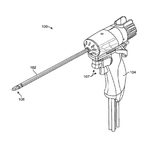
[0022] FIG. 1 shows one embodiment of a vapor delivery system.
[0023] FIGS. 2A-2B show close-up views of a distal portion of the vapor
delivery system including a
vapor delivery needle.
[0024] FIGS. 2C-2D show a normal prostate and an enlarged prostate being
treated with a vapor
delivery system.
-4b-
Date Regue/Date Received 2022-10-20
CA 02972819 2017-06-29
WO 2016/123498
PCT/US2016/015684
[0025] FIGS. 3A-3B show a vapor delivery system including an inductive
heating system for
producing high quality condensable vapor.
[0026] FIG. 4 shows a generator unit configured to control generation of
vapor in the
inductive heating system.
[0027] FIG. 5 shows one embodiment of a syringe assembly that interacts
with the generator
unit.
[0028] FIG. 6 shows a cross-sectional view of a syringe cradle and
syringe assembly of the
generator unit.
[0029] FIG. 7 is a cross-sectional view of a shaft of the vapor delivery
system.
DETAILED DESCRIPTION OF THE INVENTION
[0030] in general, one method for treating BPH comprises introducing a
heated vapor
interstitially into the interior of a prostate, wherein the vapor controllably
ablates prostate tissue.
This method can utilize vapor for applied thermal energy of between 50
calories and 300 calories
per each individual vapor treatment (and assumes multiple treatments for each
prostate lobe) in
an office-based procedure. The method can cause localized ablation of prostate
tissue, and more
particularly the applied thermal energy from vapor can be localized to ablate
tissue adjacent the
urethra without damaging prostate tissue that is not adjacent the urethra.
[0031] The present disclosure is directed to the treatment of BPH, and
more particularly for
ablating transitional zone prostate tissue without ablating central or
peripheral zone prostate
tissue. In one embodiment, the present disclosure is directed to treating a
prostate using
convective heating in a region adjacent the prostatic urethra. The method of
ablative treatment is
configured to target smooth muscle tissue, alpha adrenergic receptors,
sympathetic nerve
structures and vasculature parallel to the prostatic urethra between the
bladder neck region and
the verumontanum region to a depth of less than 2 cm.
[0032] The system can include a vapor delivery mechanism that delivers
vapor media,
including water vapor. The system can utilize a vapor source configured to
provide vapor having
a temperature of at least 60-140 C. In another embodiment, the system further
comprises a
computer controller configured to deliver vapor for an interval ranging from 1
second to 30
seconds.
[0033] In some embodiments, the system further comprises a source of a
pharmacologic
agent or other chemical agent or compound for delivery with the vapor. These
agents include,
without limitation, an anesthetic, an antibiotic or a toxin such as Botox", or
a chemical agent that
can treat cancerous tissue cells. The agent also can be a sealant, an
adhesive, a glue, a superglue
or the like.
- 5 -
CA 02972819 2017-06-29
WO 2016/123498
PCT/US2016/015684
[0034] FIG. I shows one embodiment of a vapor delivery system. Vapor
delivery system
100 can have an elongate shaft 102 configured for insertion into the urethra
of a patient and a
handle portion 104 for gripping with a human hand. The vapor delivery system
100 can include
a vapor delivery needle 106 disposed in the shaft that is configured to extend
from a distal
portion of the elongate shaft 102. The vapor delivery needle can extend
generally perpendicular
to or transverse from the shaft, and can include one or more vapor delivery
ports configured to
deliver a flow of vapor media from the needle into prostate tissue. The vapor
delivery system
100 can further include one or more triggers, buttons, levers, or actuation
mechanisms 107
configured to actuate the various functions of the system. For example, the
actuation mechanism
can be configured to extend/retract the vapor delivery needle, and start/stop
the flow of vapor,
aspiration, and a cooling and/or irrigation fluid such as saline.
[0035] In some embodiments, the triggers or actuation mechanisms 107 can
be manipulated
in such a way as to control varying degrees or flow rates of vapor and/or
irrigation. In one
specific embodiment, the triggers or actuation mechanisms 107 can comprise a
first trigger
configured to extend/retract the vapor delivery needle, a second trigger
configured to start/stop
the flow of vapor, and a third trigger configured to provide a cooling and/or
irrigation fluid such
as saline. In another embodiment, a single trigger or actuation mechanism can
both
extend/retract the vapor delivery needle and start/stop the flow of vapor. In
one embodiment, a
single press or depression of one of the triggers, such as a trigger that
provides the cooling and/or
irrigation fluid, may provide a standard irrigation flush, while a rapid
double press or depression
of the trigger may provide a "turbo" irrigation flush in which the flow rate
of irrigation is
increased over the standard flush flow rate. This feature may be useful, for
example, if the
physician encounters a blockage, needs additional cooling, or has reduced
vision in the urethra
and/or prostate due to accumulation of blood or other bodily fluids.
[0036] The fluid or irrigation source can provide a fluid, such as saline,
through a separate
lumen in the shaft to provide irrigation and flushing to tissue during
insertion of the system and
during vapor delivery to tissue. In some embodiments, the irrigation can be
used to clear blood
and debris from tissue lumens to increase visibility. The irrigation can also
provide cooling to
the urethra of the patient, both via direct contact of the irrigation fluid
with the urethra as well as
cooling the shaft of the vapor delivery system as the fluid flows from the
irrigation source
through the shaft and into contact with the tissue. Urethral flush can be used
during the lesion
formation. In one embodiment, the flush rate can be approximately 80 mL /
minute, or ranging
from 20 to 400 mI, / minute. Changes in flush rate will change the amount of
tissue cooling
(depth) into the urethra and prostate, which can affect lesion size.
- 6 -
CA 02972819 2017-06-29
WO 2016/123498
PCT/US2016/015684
[0037] FIG. 2A shows a close-up view of the distal portion of the shaft
of vapor delivery
system 100, including the vapor delivery needle 106 extending beyond the shaft
and exposing
the vapor delivery ports 108. Vapor delivery ports 108 may be arranged in a
pattern that
optimizes the delivery of vapor to tissue in a given application. For example,
in a system
designed for treatment of BPH the delivery ports 108 comprise multiple rows of
a plurality of
vapor delivery ports. In one specific embodiment, the delivery ports 108 can
be spaced at 120
degree intervals around the circumference of the needle, with one row of
delivery ports facing
distally from the front edge of the needle, as shown in Fig. 2B, to ensure
ablation of tissue
adjacent to the prostatic urethra. In general, the vapor delivery ports can
each have a unique
.. diameter. In one embodiment the vapor delivery ports all have the same
diameter.
[0038] Fig. 2C shows a normal, healthy prostate, and Fig. 2D shows an
enlarged prostate
being treated with a vapor delivery system 100. In one embodiment, the vapor
delivery system
can be inserted into the urethra and advanced to the prostatic urethra through
a transurethral
approach. The vapor delivery needle 106 can be advanced generally transverse
to the shaft of
the vapor delivery system and into the prostate tissue. Vapor can be generated
by the vapor
delivery system and delivered into the prostate through the vapor delivery
needle. As described
above, the vapor delivery needle can include a row of vapor delivery ports
that point distally
away from the device when the vapor delivery needle is extended transverse to
the shaft of the
device. Referring to Fig. 2D, the vapor can be delivered to the prostate
through this distally
facing vapor delivery ports to ablate prostate tissue distal to the position
of the vapor delivery
needle in the prostate. The position of the vapor delivery needle and the
vapor delivery ports can
allow for ablation of transition zone tissue of the prostate extending
distally from the position of
the vapor delivery needle. For example, in Figure 2D transition zone tissue is
treated that
extends under bladder muscular tissue that cannot be safely penetrated by a
delivery device
.. needle.
[0039] The vapor delivery system 100 can include a vapor source, an
aspiration source, a
fluid cooling or irrigation source, a light source, and/or an electronic
controller configured to
control generation and delivery of vapor from the vapor source, through a
lumen of the shaft,
through the vapor delivery needle, and into prostate tissue. In some
embodiments, the electronic
controller can be disposed on or in the vapor delivery system, and in other
embodiments the
electronic controller can be disposed separate from the system.
[0040] A vapor source can be provided for generating and delivering a
vapor media through
the vapor delivery needle to ablate tissue. In one embodiment, the vapor
source can be a vapor
generator that can deliver a vapor media, such as water vapor, that has a
precisely controlled
quality to provide a precise amount of thermal energy delivery, for example
measured in calories
- 7 -
CA 02972819 2017-06-29
WO 2016/123498
PCT/US2016/015684
per second. In some embodiments, the vapor source can comprise an inductive
heating system
disposed in the vapor delivery system (e.g., in the handle) in which a flow
media is inductively
heated to generate a condensable vapor such as steam.
[0041] Figs. 3A-3B illustrate one embodiment of an inductive heating
system 320,
comprising an inner fluid coil 322 (shown in Fig, 3A) surrounded by an outer
electrically
conductive coil 324 (Fig. 3B). The inner fluid coil can be constructed from
steel tubing which
may be annealed. The inner fluid coil may be soldered or include a solder
stripe to insure
electrical conductivity between coil windings. The outer conductive coil can
be a conductive
material, such as electrically insulated copper Litz wire having an overall
diameter ranging from
18 gauge to 22 gauge. As shown, the inductive heating system 320 can be
disposed within the
vapor delivery system, such as within the handle. An inlet portion 326 of the
inner fluid coil 322
can receive a fluid, such as sterile water, from an external fluid source. The
fluid can pass
through the inner fluid coil 322 as AC or RF current is applied to the outer
conductive coil 324
via electrical connections 325. Current flowing in the outer conductive coil
can induce currents
to flow in the inner fluid coil that resistively heat the fluid within the
inner fluid coil so as to
produce a high quality condensable vapor, which is then delivered to the vapor
delivery needle
via outlet portion 328.
[0042] Fig. 4 illustrates a generator unit 40 configured to provide power
and fluid to the
inductive heating system for the production of vapor. The generator unit also
can connect to the
vapor delivery system 100 described above to provide power and other
components to the
system vital for operation, such as irrigation/cooling fluid, suction, etc.
The generator unit can
include an electronic controller and a graphical user interface (GUI) 434 to
provide operating
parameters and controls to the user during vapor therapy. The generator unit
can include a
syringe cradle 430 adapted to hold syringe assembly 536 for providing fluid,
such as sterile
water, to the inductive heating system.
[0043] The generator unit can also include an electrical connector 432
which can provide rf
current to the inductive heating system, electrical signals to and from the
switches 107 of the
vapor delivery system, measurements of, for example, the temperature of the
inductive heating
system, and electrical signals to/from a controller of vapor delivery system,
for example in its
electrical connector, to identify the vapor delivery system, track its history
of vapor delivery,
and prevent excessive use of a given vapor delivery system. Generator unit 40
may also contain
the peristaltic pump 435 that provides a flow of cooling/irrigation fluid such
as saline to the
vapor delivery system. In operation, flexible tubing 437 can be routed from a
bag of sterile
saline, through the peristaltic pump, and through tubing into the vapor
delivery system. Guides
or markers can be provided on the peristaltic pump 435 to insure that the
tubing is inserted in a
- 8 -
CA 02972819 2017-06-29
WO 2016/123498
PCT/US2016/015684
path that provides flow in a direction from the saline bag into the vapor
delivery system when the
pump is activated normally.
[0044] Fig. 5 shows syringe assembly 536 that provides a precise amount
of fluid such as
sterile water to the vapor delivery system 100 for conversion into vapor.
Syringe assembly 536
includes a syringe 537 having exit port 541 that is offset from the center
line of the syringe, with
luer fitting 542 that connects to sterile water tubing on the vapor delivery
system, plunger 538
that moves forward in the syringe to eject water, and backward in the syringe
to fill the syringe
with water, and accessory rod 540 that removably attaches to plunger 538
during system set-up
to fill syringe 537. When syringe 537 has been filled with fluid, accessary
rod 540 is discarded,
to and filled syringe 537 is inserted into the cradle of the generator
unit.
[0045] Fig, 6 shows a cross-sectional view of the syringe cradle 430 of
Fig. 4, with the
syringe assembly 536 of Fig. 5 inserted into cradle 430. A contact switch 654
is activated when
syringe 537 is inserted into cradle 430 to insure that the syringe is in place
when power is
delivered to the vapor delivery system. The state of the contact switch is
sensed through
electrical leads 652. A force sensor 644 is disposed in the cradle such that
it contacts and
interacts with the cradle and/or syringe assembly 537. When the electronic
controller is
commanded to deliver sterile water to the vapor delivery system, piston 642 of
the cradle
engages syringe plunger 538, and a linear motor attached to piston 642
delivers sterile water at a
precisely controlled rate from syringe 537 out through luer fitting 542 into
fluid tubing
connected to the inductive heating system. As sterile water is pushed, syringe
537 impinges on
cradle 430, which is free to move laterally within generator 40. Forward
movement of cradle
430 is prevented as it impinges upon force sensor 644. Microscopic lateral
movement of force
sensor 644 is translated into an electrical signal that is proportional to the
force exerted on force
sensor 644 by cradle 430. The electrical signal is conducted through leads 648
to the electronic
controller and calibrated as the water pressure within syringe 537 and
throughout the fluid tubing
including within the inner coil of the inductive heating system. Water
pressure is monitored by
the electronic controller of the generator unit 40, and the electronic
controller can be configured
to stop delivery of RF power and fluid to the inductive heating system if the
fluid pressure falls
outside of a desired range of pressures, e.g., if the fluid pressure is too
low (for example due to a
leak in the water line), or too high (for example due to a blockage in the
water line).
[0046] Cradle 430 is configured to purge any air from the fluid tubing
during a priming
procedure in which water is forced from the syringe and fills and flushes the
system water and
vapor lines, exiting from the vapor delivery ports of the vapor delivery
device. As shown in Fig.
6, cradle 430 is designed so as to keep the distal end of syringe 537 at a
higher elevation than its
proximal end when inserted into the cradle, and to keep offset exit port 541
of the syringe at the
- 9 -
CA2972819
top of the syringe. This design forces any air in the syringe to move under
the influence of gravity to
the upper distal end of the syringe and to exit the syringe to be purged from
the fluid tubing during the
priming procedure. Removal of air from the fluid tubing prevents over heating
of the inductive heating
system, and prevents loss of water volume and therefore loss of calories
delivered to tissue.
[0047] The electronic controller of the generator unit can be set to
control the various parameters of
vapor delivery, for example, the controller can be set to deliver vapor media
for a selected treatment
interval at a selected flow rate, a selected pressure, or selected vapor
quality. Further details on the
vapor delivery system, the vapor generator, and how vapor and fluid are
delivered to tissue can be found
in US Patent No. 8,273,079 and PCT Publication No. WO 2013/040209. In some
embodiments, the
electronic controller can also control the aspiration and/or cooling
irrigation functions of the vapor
delivery system.
[0048] FIG. 7 provides a cross sectional view of elongate shaft 102 of
vapor delivery system 100
from FIGS. 1-2. Lumen 148 can be configured to accommodate the vapor delivery
needle described
above and in FIGS. 1-2, to allow for the vapor delivery needle to be advanced
from the shaft during
vapor delivery. Lumen 115 formed within tube 112 can have a diameter ranging
from about 2 to 5 mm
for accommodating various endoscopes 118, while at the same time providing an
annular space 138 for
allowing an irrigation fluid to flow within lumen 115 and outwardly from the
shaft into the distal urethra
and bladder. The lumen 115 can be sized to accommodate an endoscope or camera
to provide
additional viewing and feedback to the physician. This endoscope or camera can
provide a view of the
distal end of the shaft, including a view of the vapor delivery needle when
deployed. As can be seen in
FIG. 7, the lumen 115 is dimensioned to provide a space 138 for fluid
irrigation flow around the
endoscope 118. In some embodiments, the annular space 138 can be a separate
concentric lumen
around the endoscope for irrigation fluid flow. The annular space 138 allows
for flow of irrigation fluid
from the vapor delivery system into tissue, and also provides cooling to the
shaft when vapor is
delivered from the vapor delivery needle (disposed in lumen 148) into tissue.
Material 144 in FIG. 7
can conduct heat from the vapor delivery needle to the irrigation/cooling
fluid flowing in annular space
138, or alternatively, can conduct cooling from the irrigation/cooling fluid
to the vapor delivery needle,
to prevent over-heating of the patient (particularly the urethra) during vapor
therapy.
[0049] Although particular embodiments of the present invention have
been described above in
detail, it will be understood that this description is merely for purposes of
illustration and the above
description of the invention is not exhaustive. Specific features of the
invention are
- 10 -
Date Recue/Date Received 2022-05-13
CA 02972819 2017-06-29
WO 2016/123498
PCT/U52016/015684
shown in some drawings and not in others, and this is for convenience only and
any feature may
be combined with another in accordance with the invention. A number of
variations and
alternatives will be apparent to one having ordinary skills in the art. Such
alternatives and
variations arc intended to be included within the scope of the claims.
Particular features that are
presented in dependent claims can be combined and fall within the scope of the
invention. The
invention also encompasses embodiments as if dependent claims were
alternatively written in a
multiple dependent claim format with reference to other independent claims.
- 11 -