Note: Descriptions are shown in the official language in which they were submitted.
TITLE OF THE INVENTION: SUPPORT STRUCTURE FOR CARRYING STRAP AND
CARRYING STRAP FOR DISTRIBUTING LOAD
BACKGROUND OF THE INVENTION
[0001] The present invention is directed to an apparatus for use with carrying
straps, or carrying
straps incorporating the apparatus, which are placed over the back of the neck
or the shoulder to
carry devices such as cameras, bags and the like. In particular, the present
invention is directed to
an apparatus which focuses the weight supported by the carrying strap in a
point fashion over a
major muscle group of the back of the neck or the shoulder.
FIELD OF THE INVENTION
[0002] Many devices such as cameras, bags and the like are provided with
carrying straps which
allow the device to be supported by placing the carrying strap over the
shoulder or around the
back of the neck. The carrying straps are generally a fabric or leather strap
attached at either end
to the device. In order to distribute the weight of the device, the carrying
strap is generally a wide
strap to allow for a larger surface area for distributing weight or if the
strap is a narrow strap it
may be provided with a wider padded support pad which is generally slidably
attached the strap.
While such straps distribute the weight of the device over a broader area of
the neck or shoulder,
it has been found with extended period of use the strap can still result in
fatigue and pain of the
neck or shoulder from supporting the weight of the device for such extended
period of use.
[0003] There thus still remains a need for a carrying strap for devices such
as cameras, bags and
the like which will reduce the fatigue and pain of the neck or shoulder
arising from supporting
the weight of the device for an extended period of time.
CA 2972905 2017-07-11
SUMMARY OF THE INVENTION
[0004] The present invention is directed to a carrying strap for devices such
as cameras, bags and
the like which focuses the weight supported by the carrying strap over the
underlying major
muscles of the neck or shoulder.
[0005] In an aspect of the invention the carrying strap is provided with
support structures
releasably attached to the carrying strap to lie over the underlying muscles
of the neck or
shoulder, the support structures extending below the carrying strap to
transfer the weight of the
device to the underlying muscles of the neck or shoulder.
[0006] In another aspect of the invention the support structure is a
cylindrical structure releasably
attached to the carrying strap in the proper position.
[0007] Another aspect of the invention relates to a support system for use
with a carrying strap
comprising at least two support structures each having a slot for receiving a
carrying strap and an
engagement mechanism for securing the support structure to a desired location
on the carrying
strap. In this embodiment, the support structures are spaced from each other
along a length of
the carrying strap.
[0008] In a further aspect of the invention, the support structures are shaped
to distribute forces
over a small area.
[0009] In yet a further aspect of the invention, each support structure is
cylindrical in shape.
[0010] In yet a further aspect of the invention, each support structure is
made of a molded
material.
[0011] In yet a further aspect of the invention, each support structure
further includes a gap
around a partial perimeter of the support structure. The gap is in
communication with the slot
such that a carrying strap could be passed through the gap and into the slot.
2
CA 2972905 2017-07-11
[0012] In yet a further aspect of the invention, the engagement mechanism is a
screw.
[0013] In another embodiment of the invention, the support structures are
positioned on the
carrying strap such that when the strap is in use, the support structures are
positioned to
correspond to the location of major muscles of the neck.
[0014] In a further aspect of the invention, the support structures are
positioned on said carrying
strap such that when the strap is in use, the support structures are
positioned to correspond to the
location of the trapezius muscles.
[0015] In another embodiment of the invention, the support structures are
positioned on said
carrying strap such that when the strap is in use, the support structures are
positioned over major
muscles of the shoulder.
[0016] Another aspect of the invention pertains to a carrying apparatus
comprising an elongate
strap and at least two support structures. Each support structure is coupled
to the strap in a
spaced apart manner along the length of the strap.
[0017] In a further aspect of the invention, the support structures are shaped
to distribute forces
over a small area.
[0018] In a further aspect of the invention, each support structure is
cylindrical in shape.
[0019] In a further aspect of the invention, each support structure is made of
a molded material.
[0020] In yet a further aspect of the invention, each support structure has a
slot for receiving the
elongate strap and an engagement mechanism for securing the support structure
to a desired
location on said carrying strap.
3
CA 2972905 2017-07-11
[0021] In yet a further aspect of the invention, each support structure
further includes a gap
around a partial perimeter of the support structure. The gap is in
communication with the slot
such that a carrying strap could be passed through the gap and into the slot.
[0022] In yet a further aspect of the invention, the engagement mechanism is a
screw.
[0023] In another aspect of the invention, the support structures are
positioned on the carrying
strap such that when the strap is in use, the support structures are
positioned to correspond to the
location of major muscles of the neck.
[0024] In a further aspect of the invention, the support structures are
positioned on the carrying
strap such that when the strap is in use, the support structures are
positioned to correspond to the
location of the trapezius muscles.
[0025] In another aspect of the invention, the support structures are
positioned on the carrying
strap such that when the strap is in use, the support structures are
positioned over major muscles
of the shoulder.
BRIEF DESCRIPTION OF THE DRAWINGS
[0026] A preferred embodiment of the present invention is illustrated in the
attached drawings in
which:
Figure 1 is a perspective view of the use of the carrying strap of the present
invention to support
a device around the neck;
Figure 2 is a perspective view of a preferred embodiment of the carrying strap
of the present
invention;
Figure 3 is a perspective view of the cylindrical support structure of the
carrying strap of figure
2;
Figure 4 is a perspective view of the disassembled support structure of figure
3; and
Figure 5 illustrates the releasable attachment of the cylindrical support
structure to the carrying
strap.
4
CA 2972905 2017-07-11
DETAILED DESCRIPTION OF PREFERRED EMBODIMENTS
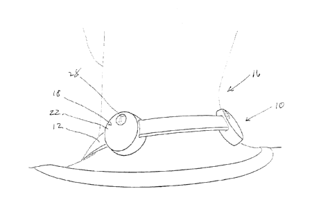
[0027] A preferred embodiment of the carrying strap of the present invention
is illustrated in the
attached drawings generally indicated by the 10. Referring now to figures 1
and 2, carrying strap
has a strap 12 having two ends 14 for attaching to the device to be carried by
looping the strap
over the shoulder or around the neck 16. In the embodiment illustrated in the
drawings, strap 12
is a leather strap, however the strap may be any material known in the art for
use in carrying
straps.
[0028] The carrying strap 10 is also provided with support structures 18 which
are placed so that
they will rest on the major muscles of the neck, in particular the trapezius
muscle. The position
of the support structures may also generally correspond to acupressure points.
In the preferred
embodiment shown in the figures, the support structures 18 are cylindrical in
shape having
generally flat bottom 20 and top 22 surfaces. However, a person skilled in the
art will appreciate
that other shapes such as ovals or squares or rectangles with curved or angled
corners would also
be suitable. The Support structures are sized and shaped to focus the weight
of the object being
carried over a small area which distributes the load in a point-like fashion.
[0029] As shown in figures 3 and 4, the slot 24 in the support structure
spaced from the bottom
surface 25. This spacing is such that when in use, the portion strap 12
between the two support
structures is elevated from a user's neck. This preferred embodiment keeps the
strap from
contacting the bones of the cervical spine to reduce pressure on the vertebra
as shown in figure 1.
[0030] The support structures 18 are preferably constructed of a molded
material such as a
plastic or rubber. Preferably the support structure is molded from a polymeric
plastic such as
polypropylene or polyethylene or a rubber material such as ABS or silicone.
The support
structure may also be manufactured by a 3D printing process. In an alternative
embodiment, the
support structure is made of layered leather.
5
CA 2972905 2017-07-11
[0031] The support structure 18 is also provided with a slot 24 through which
the strap passes to
allow the support structure 18 to be engaged with the strap 12 in the desired
position. The slot 24
is provided with a means to grip the strap 12 and hold the support structure
18 in the desired
position in the engagement position of the support structure 18. When the
support structure 18 is
in the unengaged or movable position the means to grip the strap 12 is relaxed
so the support
structure 18 may slide upon the strap 12 until it reaches the desired
position.
[0032] As illustrated in figures 3 to 5, the preferred embodiment of the
support structure 18 is
provided with a gap 26 on one side of the slot 24 such that the strap 12 may
be inserted into the
gap 26 until it lies within the slot 24. Once the strap 12 is in the proper
position in the slot 24, a
fastening means such as screw 28 is inserted through an opening 30 in the top
of the support
structure 18 above the gap 26 to engage a screw hole 32 provided in the bottom
of the support
structure 18 below the gap 26. When the screw 28 is tightened down, the gap 26
is closed and the
top surface of the slot 24 engages and holds the strap 12 once the support
structure 18 is located
in the desired position.
[0033] While a preferred embodiment of the present invention has been
described above and
illustrated in the drawings, it will be appreciated by those skilled in the
art that variations of the
embodiment may be made without departing from the scope of the invention. For
example while
the preferred embodiment of the support structure illustrated in the drawings
has a flat top and
bottom surface, other shapes of the surface such as a convex surface may be
provided.
[0034] Another variation relates to the means to grip the strap and hold the
support structure in
the desired position in the engagement position of the support structure.
While the preferred
embodiment utilizes the screw to tighten down the top surface of the slot to
engage the strap, an
alternative would be to merely provide the slot through the support structure
with no gap and
provide a means to clamp down on the top of the strap when the support
structure is in the
engagement position. Such a means could include a screw that when tightened
down engages the
surface of the strap to hold the support structure in position. Alternatively,
the top surface of the
slot may be provided with a biasing means which may be biased to engage the
top of the strap
when in the engagement position and be released when it is desired to move the
support
6
CA 2972905 2017-07-11
structure. One example of a biasing means would be a flexible bar in the top
of the slot and a
screw which could be tightened down to move the flexible bar into engagement
with the top
surface of the strap. The slot may also be provided with a coating of a
material to increase the
friction of the strap when contained in the slot in the engaged position. One
example of such a
material would be beeswax, although those of skill in the art will be aware of
other materials
which would also be suitable.
[0035] The scope of the invention should not be limited by the preferred
embodiments set forth
in the examples, but should be given the broadest interpretation consistent
with the description as
a whole.
7
CA 2972905 2017-07-11