Note: Descriptions are shown in the official language in which they were submitted.
WET GAS COMPRESSION
[00011 <<This paragraph has been left intentionally blank.>>
BACKGROUND
[0002] This section is intended to introduce various aspects of the art,
which may be
associated with exemplary embodiments of the present invention. This
discussion is believed
to assist in providing a framework to facilitate a better understanding of
particular aspects of
the present invention. Accordingly, it should be understood that this section
should be read in
.. this light, and not necessarily as admissions of prior art.
[0003] Traditionally, it is understood that centrifugal compressors or
gas expanders do not
handle liquid slugs and thus it is assumed that they can only handle a
fraction of one percent
liquid by volume. Thus in many applications expensive liquid separators,
dehydration
processes and/or unit scrubbers are utilized to try and remove or separate the
liquids prior to
using centrifugal compressors or expanders. These devices are often designed
for specific
operating conditions and are then limited in the range of Gas Volume Fraction
(GVF) that can
be handled with a given process flow rate. Even with this expensive and
complex processing
equipment, if there is a sudden high level of liquids they can quickly
saturate, fill and overflow
the liquid separators once their capacity for liquid is exceeded resulting in
slugging the
compressor or expander equipment.
100041 In general, multiphase pumps can be used if it is known that the
fluid will generally
be below 90% GVF. Centrifugal compressors are often restricted to applications
with GVFs of
99.7 or higher and even this can cause problems within the machine for
stability and affecting
the reliability of the seals and bearings. Therefore, for processes outside
this small range, the
current practice is to separate the fluids prior to utilizing a centrifugal
compressor even with the
design limitation with the associated process and equipment. The same is true
for gas
expanders, which are functionally a centrifugal compressor running in reverse
to extract energy
in one form or another through a process pressure drop across the expander.
The separators,
scrubbers and dehydration units are not only expensive and limited in liquid
capacity and
volume flow range but they also tend to be very bulky, taking up expensive
real
- 1 -
CA 2972928 2018-12-20
CA 02972928 2017-06-30
WO 2016/153627 PCT[US2016/017703
estate in locations such as offshore platforms, subsea processing or onshore
facilities. This
coupled with complex control systems and additional auxiliary equipment like
pumps,
regulators, level controllers, transmitters and filters adds to the complexity
and likelihood of
failure of these systems. An example of a typical oil or gas well stream
service process may
use a separator to separate liquids from the gas in order to prevent or
mitigate damage caused
by slugs. A centrifugal compressor and pump may subsequently be used to boost
the gas and
liquid separately, with downstream recombination of the gas and liquid in
order to transport
both through a pipeline to a processing facility.
[0005] Problems with compressing liquids include reduced machine
stability, erosion of
impellers and diffusers, and fouling and resulting in imbalance if the liquids
flash or vaporize
while being compressed in the machine.
[0006] The foregoing discussion of need in the art is intended to be
representative rather
than exhaustive. Technology that would improve the ability of compressors or
expanders to
handle the multiphase flow of fluid with a higher liquid content compared to
the current state
of the art would be of great value.
SUMMARY OF THE INVENTION
[0007] The disclosure includes a centrifugal compressor, comprising an
inlet configured to
receive a gas stream, an outlet, and a liquid injection port configured to
introduce a liquid into
the gas stream and create a multiphase fluid, wherein the centrifugal
compressor is configured
to compress the multiphase fluid.
[0008] The disclosure includes a method of operating a centrifugal
compressor, comprising
passing a gas stream to a centrifugal compressor inlet, introducing a quantity
of liquid into the
gas stream to create a multiphase stream, and compressing the multiphase
stream.
DESCRIPTION OF THE DRAWINGS
[0009] So that the manner in which the present invention can be better
understood, certain
illustrations, charts and/or flow charts are appended hereto. It is to be
noted, however, that the
drawings illustrate only selected embodiments of the inventions and are
therefore not to be
considered limiting of scope, for the inventions may admit to other equally
effective
embodiments and applications.
[0010] FIG. I is an illustrative compressor performance map showing a
traditional
sequence of operating points moving into a region of higher pressure ratio /
head.
- 2 -
CA 02972928 2017-06-30
WO 2016/153627 PCT/US2016/017703
[0011] FIG. 2 is a compressor performance map plotting compressor
operation for one
percent (1%) Nominal Liquid Volume Fraction (LVF) at various flow and pressure
ratio
conditions.
[0012] FIG. 3 is another compressor performance map plotting compressor
operation for
increasing LVFs at a given speed which show how the pressure ratio varies with
the quantity
of liquid.
[0013] FIG. 4 is a schematic diagram of one embodiment of a multiphase
fluid handling
system according to the disclosure for compressing a multiphase fluid.
[0014] FIG. 5 is a schematic diagram of another embodiment of a
multiphase fluid handling
system according to the disclosure for compressing a multiphase fluid.
[0015] FIG. 6 is a schematic diagram of still another embodiment of a
multiphase fluid
handling system according to the disclosure for compressing a multiphase
fluid.
[0016] It should be noted that the figures are merely exemplary of
several embodiments of
the present invention and no limitations on the scope of the present invention
are intended
thereby. Further, the figures are generally not drawn to scale, but are
drafted for purposes of
convenience and clarity in illustrating various aspects of the invention.
DETAILED DESCRIPTION
10017] Reference will now be made to exemplary embodiments and specific
language will
be used to describe the same. It will nevertheless be understood that no
limitation of the scope
of the invention is thereby intended. Alterations of further modifications of
the inventive
features described herein, and additional applications of the principles of
the invention as
described herein, which would occur to one skilled in the relevant art and
having possession of
this disclosure, are to be considered within the scope of the invention.
Further, before particular
embodiments of the present invention are disclosed and described, it is to be
understood that
this invention is not limited to the particular process and materials
disclosed herein as such may
vary to some degree. It is also to be understood that the terminology used
herein is used for
the purpose of describing particular embodiments only and is not intended to
be limiting, as
the scope of the present invention will he defined only by the appended claims
and equivalents
thereof.
[0018] Testing has shown that erosion can be reduced or prevented by
slowing down the
liquid velocity at impact points and by reducing the droplet size. Fouling has
also been reduced
- 3 -
CA 02972928 2017-06-30
WO 2016/153627 PCT/US2016/017703
or even removed by increasing the liquid levels above the flash point in
effect washing the
internals of the machine. Disclosed techniques include using the thermodynamic
and
aerodynamic effects of liquid injection as a control method for a centrifugal
compressor system.
Whereas current technology focuses on conditioning, restricting, and/or
minimizing the
.. amount of liquid, the disclosed techniques include intentionally adding
liquid and/or changing
the liquid fraction to obtain a change in the operating condition(s) of the
compressor system.
Suitable liquids and/or injectants include one of or a combination of water,
produced water,
liquid hydrocarbons, corrosion inhibitor (e.g., water soluble or oil soluble
chemicals (often
amine based) used to inhibit aqueous corrosion), process liquid(s), diluents
(e.g., xylene, etc.),
.. liquid chemicals (e.g., glycols, amines, etc.), drilling fluids, fracking
fluids, etc. The liquids
and/or injectants may be byproducts of an existing process in a facility or a
liquid from an
external source. Suitable compressor systems include those found in surface
facilities, subsea
applications, pipeline applications, gas gathering, refrigeration, etc., as
well as future possible
configurations of centrifugal compressor systems such as in-pipe compressors
and/or down-
hole compressors.
10019] As described above, adding liquid may increase the pressure ratio
of a centrifugal
compressor. In other words, the non-compressibility of the liquid may be
utilized to increase
pressure producing capability of the compressor. For example, as reservoirs
deplete and
enhanced oil recovery (EOR) with water is undertaken, a higher compression
ratio with lower
.. volumes of gas and additional liquid may be required. Using the liquid may
replace a problem
with a benefit that may eliminate the need to re-wheel, re-stage, and/or re-
bundle a compressor.
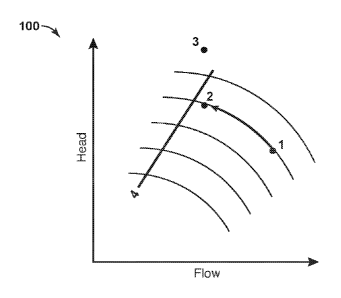
10020] FIG. I is an illustrative compressor performance map 100 plotting
pressure ratio
(PR) (the pressure at the compressor exducer versus the pressure at the
compressor inducer) or
head on the Y-axis against flow (e.g., in actual cubic feel per minute (ACFM))
on the X-axis.
.. in Fig. 1, points 1 and 2 depict exemplary operating points of a
conventional centrifugal
compressor for a given speed range over a range of flows.
[0021] Surge line 4 separates a region of unstable flow above the surge
line 4 from a region
of stable flow below the surge line 4. If a compressor operates above and/or
on the left side of
the surge line 4, the compressor may surge or pulsate backflow of gas through
the device. In
.. general, the surge line 4 may signify the minimum flow rate limit for a
given compressor.
[0022] Injecting liquid at operating point 2 allows the compressor to
increase the PR and/or
produce more head than the original design, depicted by the operating
condition moving
- 4 -
CA 02972928 2017-06-30
WO 2016/153627 PCT/US2016/017703
vertically along the performance map to point 3. As described above, the
ability to increase
the PR may be advantageously exploited in a variety of contexts, e.g., EOR
operations, to
accommodate lower wellhead pressure, to compensate for changing gas
composition, to
counter increased resistance in an associated discharge system, etc. In some
embodiments,
liquid ingestion increases the pressure ratio above pre-established surge
limits but does not
cause the surge phenomenon to occur. Additionally, injecting liquid may extend
the surge
range of a given compressor, thereby permitting compressors to operate in low
flow regions
without exhibiting excessive pressure reversals or oscillating axial shaft
movement. This
technique may be more efficient than opening a recycle line (current
technology) or venting
gas at an inlet of the compressor. Further, injecting liquid may mitigate
possible slugging and
liquid carry-over damage to brownfield compressors. For example, a static
mixer at a
compressor inlet nozzle may atomize a liquid into droplets to reduce possible
slugging on the
compressor when existing (brownfield) suction scrubbers have liquid carry-over
(e.g., due to
instrument failure, system upsets, operator error, change in
scrubber/separator performance as
inlet pressures decrease, gas compositions change which may increase liquid
loading, etc.). As
used herein, the term "atomize" means to divide, reduce, or otherwise convert
a liquid into
minute particles, a mist, or a fine spray of droplets having an average
droplet size within a
predetermined range. In some embodiments, a flow mixer in the suction line may
provide an
order of magnitude reduction in droplet size, effectively atomizing the
liquid. Atomized liquid
may represent a lower risk to rotating parts than large droplets or slugs of
liquid, thereby
substantially reducing the business risk of liquid carry-over events (e.g.,
damaged compression
components). However, it is contemplated that these benefits may be outweighed
and non-
atomized liquid may be suitable in other contexts.
[00231 FIG, 2 is a compressor performance map 200 plotting compressor
operation for an
injection of one percent (1%) Nominal Liquid Volume Fraction (LVF) for an
embodiment of
the disclosed technique. The Y-axis is the PR and the X-axis is the air flow
in ACFM. Initially,
a compressor was measured at three different operating conditions using a
compressor speed
of 8,000 revolutions per minute (RPM) and 9,000 RPM on dry gas. Move 1 shows
the data
associated with adding an injectant, e.g., water, to obtain a 1% LVF input
stream. Move 2
shows the adjustment to flow made to obtain substantially the same PR for the
compressor at
the given speed and with a 1% LVF input stream. As depicted, increasing the
LVF (Move 1)
increased the PR for a given flow at a given compressor speed at lower flow
rates and had a
negligible or lessening effect at higher flow rates. In other words, injecting
liquid translated
- 5 -
CA 02972928 2017-06-30
WO 2016/153627 PCT/US2016/017703
the operating curve in a clockwise orientation about a known point. In Move 2,
the air flow
was increased while the liquid flow rate was held constant to reduce the PR
back to
substantially the same as the dry value. As depicted, Move 2 translated the
curve to the right
along the X-axis, compressed the curve, and further translated the curve
clockwise about a
known point.
100241 FIG. 3 is a compressor performance map 300 plotting compressor
operation for an
injection of various LVFs, i.e., 1% LVF, 2.8% LVF, and 3.8% LVF, at a given
speed (8,000
RPM). The Y-axis is the PR and the X-axis is the air flow in ACFM. As
depicted, for a given
compressor operating speed, e.g., 8,000 RPM, increasing the LVF tends to raise
the PR at lower
flows and has a negligible or lessening effect on the PR at higher flow rates.
In other words,
raising the LVF by injecting liquid translates the operating curves in a
clockwise orientation
about a known point.
10025] FIG. 4 is a schematic diagram of a compression system 400, Fluid,
for example
fluid from a well head or separator, is directed to the apparatus by a conduit
450, check valve
451, and conduit 452. The mixture of liquid and gas enters a fluid treatment
device 455. The
fluid treatment device 455 may be a slug suppressor or a known atomizing
device, such as one
or more atomizing nozzles or flow mixers, to include a static flow mixer, a
dynamic flow mixer,
or a combination thereof. The fluid treatment device 455 may also be a
combination of these
elements. Suitable atomizers may generate droplets having an average droplet
size on the order
of about 1,000 um to about 1,500 um, about 1,000 um to about 2,000 um, about
2,000 um to
about 3,000 um, or larger, while other suitable atomizers, e.g., gas-assisted
atomizers, may
generate droplets having an average droplet size at least an order of
magnitude less than the
large droplets (e.g., from about 50 um to about 100 um, about 100 um to about
200 um, about
50 um to about 200 m etc.). The mixture leaving the fluid treatment device 455
flows through
conduit 456 to compressor 458 driven by a driver 457, e.g., a motor, a
turbine, a variable
frequency drive (VIM), etc. In some embodiments, a multi-phase flow meter
(MPFM) device
(not pictured) is disposed in the conduit 456 to accomplish liquid injection.
In some
embodiments, this MPFM is disposed close to the compressor suction nozzle to
minimize the
likelihood of atomized droplets coalescing in the inlet nozzle and/or
compressor volute. Such
embodiments may utilize the MPFM output to control the ratio of the various
streams to obtain
the required amount of liquid to obtain the desired operating characteristic,
e.g., power,
temperature, pressure, erosion characteristics, etc. Additionally, for
embodiments having a
- 6 -
CA 02972928 2017-06-30
WO 2016/153627 PCT1US2016/017703
plurality of inlet sources, the MPFM may be configured to receive a plurality
of inlet sources
or a plurality of MPFMs may be individually employed for each of the inlet
sources.
Compressed fluid leaves compressor 458 through conduit 460 and 461 to check
valve 462 and
to a distribution conduit 463 which delivers the compressed fluid to a desired
location. A
recycle line for the mixture from compressor 458 is provided at 466 that
includes a recycle
valve 467, and check valve 469. In some embodiments, the distribution conduit
463 may
include additional branches, after coolers, moisture separators or other
devices for
separating/treating the liquid from the gas and passing a single phase stream
downstream out
of the compression system 400. Those of skill in the art will appreciate that
the compressor
458 may be any suitable centrifugal compressor, e.g., a multi-stage
centrifugal compressor,
within the scope of this disclosure.
100261 FIG. 5 is a schematic diagram of an exemplary compression system
500 in
accordance with this disclosure. The components of FIG. 5 are substantially
the same as the
corresponding components of FIG. 4 except as otherwise noted. The compression
system 500
includes an optional suction scrubber 502. In the compression system 500, the
fluid treatment
device 455 is a flow mixer and/or atomizer, e.g., an atomizer comprising one
or more atomizing
nozzles or a flow mixer device comprising two or more counter swirling vanes
or counter
rotating vortices. The compression system 500 depicts a feedback loop 504
having a controller
506. The controller 506 may monitor discharge pressure and control the
injectant fed back to
the compression system 500 via the feedback loop 504. The feedback loop 504 is
depicted in
dashed lines to illustrate the optional configurations alternately or
cumulatively available in
some combinations and permutations contemplated herein. For example, if
injection location
508 is selected, injectant may be metered and/or injected internally to the
compressor 458 at
any one or more of the illustrated locations, e.g., the compressor inlet
and/or a compressor
interstage passage. Alternately or additionally, if injection location 510 is
selected, injectant
may be metered and/or injected upstream of the fluid treatment device 455. The
injection
location 508 and injection location 510 may have the same or different liquid
supply, and in
various embodiments may each have one or more different liquid supplies. The
injection
location 508 and the injection location 510 may utilize one or a plurality of
liquid injection
ports to pass liquid to the compression system 500. In some embodiments, one
or more liquid
injection ports may be disposed upstream of a fluid treatment device 455. In
some
embodiments, one or more liquid injection ports may be disposed on the
compressor 458, e.g.,
at the compressor inlet and/or a compressor interstage passage. In embodiments
having a
- 7 -
CA 02972928 2017-06-30
WO 2016/153627 PCT1US2016/017703
plurality of liquid injection ports, each port may be separately controlled or
controlled as part
of a bank of liquid injection ports with respect to the quantity of liquid
passed therethrough.
Alternatively or additionally, in embodiments having a plurality of liquid
injection ports, one
or more liquid injection ports may be configured to pass a different liquid
than another liquid
injection port.
100271 FIG. 6 is a schematic diagram of another embodiment of a
compression system 600
in accordance with this disclosure. The components of FIG. 6 are substantially
the same as the
corresponding components of FIG. 5 except as otherwise noted. The compression
system 600
further comprises a process inlet 602 for admitting process fluid, e.g., a
process gas, and a
multiphase flow meter 606. Other embodiments may utilize multiple process
inlets 602, e.g.,
to accommodate multiple process gases, but only one is shown in FIG. 6.
Similarly, other
embodiments may utilize multiple conduits 450 (and/or associated control
and/or feedback
loops) within the scope of this disclosure, e.g., to accommodate multiple
kinds of liquids, but
only one is shown in FIG. 6. The multiphase flow meter 606 may generate the
set point to
control the amount of wet gas entering the compressor 458 via the fluid
treatment device 455.
Those of skill in the art will appreciate that other embodiments ma),,'
alternately or additionally
control the amount of dry gas entering the compressor to similar effect. A
feedback loop 604
is provided for aiding in the control of the amount of wet gas entering the
compressor 458, e.g.,
using the control valve 605. A second feedback loop 504 is provided for
substantially the same
purpose as the feedback loop 504 of FIG. 5. The feedback loop 604 and the
feedback loop 504
are depicted in dashed lines to illustrate other optional configurations
alternately or
cumulatively available in some combinations and permutations contemplated
herein. As
shown, the feedback loop 504 couples the conduit 461 to the multiphase flow
meter 606 for
wet gas recycling. Those of skill in the art will appreciate that alternate
embodiments may
include one or more additional feedback loops for speed control, discharge
throttling, suction
throttling, recycle control, inlet guide vane control, etc.
100281 In operation, the PR for the compression systems 400, 500, and 600
may be
controlled by introducing a liquid injectant into an input stream (e.g.,
passed via conduit 450)
to create a multiphase input stream. The compression systems 400, 500, and 600
may compress
the multiphase input stream with a centrifugal compressor (e.g., the
compressor 458) to create
a multiphase discharge stream (e.g., passed via conduit 461). The compression
systems 400,
500, and 600 may measure (e.g., using the multiphase flow meter 606) a
parameter of the
streams (e.g., suction pressure, discharge pressure, suction flow, discharge
flow, and/or
-8-
CA 02972928 2017-06-30
WO 2016/153627 PCT/US2016/017703
multiphase composition), wherein the discharge parameter corresponds to a PR
for the
centrifugal compressor. When the measured parameter exceeds a first
predetermined point
(e.g., when the measured PR drops below a minimum PR set point, when the
compressor starts
to surge, when the moisture composition of the measured stream passes an
impeller erosion
limit, etc.), a control system (e.g., the controller 506) may increase or
decrease the pressure
ratio by increasing or decreasing (e.g., by manipulating the recycle valve
467õ the control valve
605, etc.) the quantity of liquid introduced into the compression systems 400,
500, and 600.
Again, the liquid may be atomized for purposes of minimizing erosion, but for
purposes of
controlling the operating point it may be non-atomized.
[0029] While it will be apparent that the invention herein described is
well calculated to
achieve the benefits and advantages set forth above, it will be appreciated
that the invention is
susceptible to modification, variation and change without departing from the
spirit thereof
- 9 -