Note: Descriptions are shown in the official language in which they were submitted.
CA 02973111 2017-07-05
SPECIFICATION
[TITLE OF INVENTION] Target Vehicle Speed Generation Device and Drive Control
Device
[TECHNICAL FIELD]
The present invention relates to a target vehicle speed generation device and
a drive control
device. More specifically, the present invention relates to a target vehicle
speed generation
device that generates a target vehicle speed for controlling the drive of a
vehicle, and a drive
control device that controls the autonomous drive of a vehicle.
[BACKGROUND ART]
Attempts are being made to develop an autonomous drive control device that is
capable of
autonomously controlling a vehicle from a departure point to a destination
(for example refer to
Patent Document 1). In this type of autonomous drive control device, for
example, a course
(route) of a vehicle from a departure point to a destination is calculated
using a well-known
navigation technique, and lanes and obstacles on the course are detected using
sensing
technology, such as a radar sensor, an image sensor, etc. The autonomous drive
control device
causes the vehicle to drive autonomously along a course based on the detected
information.
[PRIOR ART DOCUMENTS]
[PATENT DOCUMENTS]
[Patent Document 1] Japanese Laid-Open Patent Publication No. 2011-240816
[DISCLOSURE OF THE INVENTION]
[OBJECT THE INVENTION IS TO ACHIEVE]
In such an autonomous drive control, if a stop instruction or a deceleration
instruction is
output while the vehicle is accelerating, causing a sudden switch to
deceleration, the behavior of
the vehicle is suddenly greatly changed, and there is the possibility that the
user will feel
discomfort in the ride quality. Additionally, there is the possibility that
the user will also feel
discomfort when an acceleration instruction is output while the vehicle is
decelerating, causing a
sudden switch to acceleration.
An object of the present invention is to provide a drive control device that
reduces discomfort
that is felt by the user when controlling a vehicle during such autonomous
driving.
[MEANS OF ACHIEVING THE OBJECT]
The target vehicle speed generation device of a vehicle as one embodiment of
the present
invention comprises a determination unit and a correction unit. The
determination unit
2
determines whether or not a sudden change point, at which the acceleration
changes in
excess of a predetermined condition, is present in the target vehicle speed
contained in the
target route information of the vehicle, which is set in advance. The
correction unit corrects
the target vehicle speed so as to eliminate the sudden change point, if it is
determined that a
sudden change point is present by the determination unit.
The drive control device, as another embodiment of the present invention, is a
drive
control device of a vehicle that has a distance measurement unit that measures
the distance to
an object to be measured, comprising an acceleration determination unit and a
detection
distance setting unit. The acceleration determination unit determines whether
or not the
acceleration of the vehicle is greater than a predetermined acceleration
threshold value. The
detection distance setting unit increases the detection distance of the
distance measurement
unit if it is determined that the acceleration of the vehicle is greater than
the predetermined
acceleration threshold value by the acceleration determination unit.
According to another embodiment, the present invention provides a target
vehicle
speed generation device configured to set a target vehicle speed of a vehicle
that is traveling
on a target pathway set in advance, the target vehicle speed generating device
comprising:
a determination unit that determines whether or not a sudden change point at
which
acceleration changes in excess of a predetermined condition is present when
the vehicle is
accelerating or decelerating in accordance with the target vehicle speed; and
a correction unit that corrects the target vehicle speed so as to eliminate
the sudden
change point, if it is determined that the sudden change point is present by
the determination
unit.
[EFFECT OF THE INVENTION]
According to the present invention, it becomes possible to provide a target
speed
generation device and a drive control device that reduce discomfort that is
felt by the user
when controlling the autonomous driving of a vehicle.
[BRIEF DESCRIPTION OF THE DRAWINGS]
[Figure 1] is a block diagram illustrating the drive control device according
to a first
embodiment.
CA 2973111 2019-04-23
2a
[Figure 2] is a block diagram illustrating the target route generation ECU of
the drive
control device.
[Figure 3] is a schematic view describing the update of the target route.
[Figure 4] is a flowchart describing the correction of the target vehicle
speed
according to the first embodiment.
[Figure 5] is a graph describing the target vehicle speed before correction
according
to the first embodiment.
[Figure 6] is a graph describing the generation of a target vehicle speed
after
correction according to the first embodiment.
[Figure 7] is a graph describing the target vehicle speed before correction
according
to the first embodiment.
CA 2973111 2019-04-23
= CA 02973111 2017-07-05
3
[Figure 8] is a graph describing the generation of a target vehicle speed
after correction
according to the first embodiment.
[Figure 9] is a block diagram illustrating the drive control ECU according to
the second
embodiment.
[Figure 101 is a flowchart describing the control of the radar detection
distance according to a
second embodiment.
[EMBODIMENTS TO CARRY OUT THE INVENTION]
(1) First embodiment
The drive control device 10 according to the first embodiment will be
described with
reference to Figure 1-Figure 6.
Figure 1 is a block diagram illustrating the drive control device 10 according
to an
embodiment of the invention. The drive control device 10 is a device mounted
in a vehicle, and
a device for autonomously controlling drive of the vehicle along a course
(route) from a
departure point to a destination, which is calculated using navigation
technology, or the like. In
particular, the drive control device 10 divides the course from the departure
point to the
destination into predetermined sections, updates a target route that shows the
vehicle's driving
trajectory and the vehicle's behavior (for example, vehicle speed,
acceleration, steering angle,
etc.) for each section, and controls the driving of the vehicle based on the
target route.
The drive control device 10 comprises a target route generation ECU
(Electronic Control
Unit) 12 and a drive control ECU 14, as illustrated in Figure 1. In addition,
radar 16 (distance
measurement unit), a camera 18, a driving state detection sensor 20, an
operation state detection
sensor 22, a navigation system 24, and the like, are electrically connected to
the drive control
device 10, as illustrated in Figure 1. Furthermore, a drive control actuator
26 is electrically
connected to the drive control device 10. The drive control device 10 can be
appropriately
connected to other well-known configurations, such as a communication unit for
carrying out
inter-vehicle communication.
The target route generation ECU 12 and the drive control ECU 14 are each
electronic control
units comprises a CPU (Central Processing Unit) and a memory, such as a ROM
(Read Only
Memory), a RAM (Random Access Memory), and the like. The target route
generation ECU 12
acquires map information and a course from a departure point to a destination
searched by the
navigation system 24, and calculates a target route that represents the
driving trajectory of the
CA 02973111 2017-07-05
=
4
vehicle and the behavior of the vehicle for each predetermined section that is
set on the course,
as illustrated in FIG. 2. The drive control ECU 14 controls the driving of the
vehicle based on
the target route generated by the target route generation ECU 12. For example,
the drive control
ECU 14 calculates the drive control amount of the host vehicle, such as
acceleration/deceleration
and the steering angle, based on the target route generated by the target
route generation ECU 12,
as well as data from the radar 16, the camera 18, the driving state detection
sensor 20, the
operation state detection sensor 22, and the navigation system 24.
Furthermore, the drive control
ECU 14 controls the drive control actuator 26 based on the drive control
amount. In Figure 1,
the target route generation ECU 12 and the drive control ECU 14 are described
as independent
ECUs, but the two can be integrally configured as appropriate.
The radar 16 detects the presence, position (distance and angle from the
vehicle), and speed,
as well as the relative speed with respect to the host vehicle, of a vehicle,
a motorcycle, a bicycle,
a pedestrian, and the like, surrounding the host vehicle. The radar 16
comprises, for example, a
laser radar, a millimeter wave radar, an ultrasonic radar, or the like. The
radar 16 outputs the
detected data to the drive control device 10. Since a well-known radar can be
appropriately used
as the radar 16, a detailed description of the configuration will be omitted.
The camera 18 is, for example, attached to the front or the side of the host
vehicle, and
captures an image of the host vehicle's surroundings. For example, the camera
18 captures road
section lines and obstacles on the course. The camera 18 comprises an imaging
element, such as
a CCD (Charge Coupled Device) or CMOS (Complementary Metal-oxide
Semiconductor). The
camera 18 outputs the captured image to the drive control device 10. Since a
well-known
camera can be appropriately used as the camera 18, a detailed description of
the configuration
will be omitted.
The driving state sensor 20 detects the driving state (for example, vehicle
speed, acceleration,
yaw angle, etc.) of the host vehicle. The driving state sensor 20 has, for
example, a wheel speed
sensor provided for each wheel of the host vehicle, and detects the driving
state of the host
vehicle, such as the vehicle speed, by measuring the wheel speed. The driving
state sensor 20
outputs the detected driving state of the host vehicle to the drive control
device 10. Since a well-
known vehicle speed sensor, acceleration sensor, and yaw angle sensor can be
used as the
driving state sensor 20, a detailed description of the configuration will be
omitted.
CA 02973111 2017-07-05
The operation state detection sensor 22 detects the operation state of the
host vehicle.
Specifically, the operation state detection sensor 22 detects the accelerator
operation, the brake
operation, the steering wheel operation (steering), and the like, of a user
that rides in the vehicle
(hereinafter referred to as driver). The operation state sensor 22 outputs the
detected operation
state of the host vehicle to the drive control device 10. Since a well-known
accelerator operation
sensor, brake operation sensor, and steering sensor can be used as the
operation state sensor 22, a
detailed description of the configuration will be omitted.
The navigation system 24 receives GPS signals from a GPS (Global Positioning
System)
satellite. In addition, the navigation system 24 can comprise a gyroscope that
detects the
magnitude of a rotational movement applied to the vehicle, an acceleration
sensor that detects the
drive distance of the vehicle from acceleration in three axial directions, and
the like, and a
geomagnetic sensor that detects the driving direction of the vehicle from
geomagnetism, or the
like. The navigation system 24 stores map information in a storage medium,
such as a hard disk.
This map information contains information relating to the locations and shapes
of roads and
intersections, and to traffic rules, including traffic signs, signals, and the
like. In addition, map
information can define the driveable area of the vehicle within the lane on
the road. The
navigation system 24 detects the position of the host vehicle and the
orientation with respect to
the road, based on the map information and GPS signals from a GPS satellite.
The navigation
system 24 searches a course from the departure point to the destination,
according to inputs of
the departure point (or the current position) and the destination, and carries
out route guidance to
the destination, using the searched course and the positional information of
the host vehicle. In
addition, the navigation system 24 outputs the searched course to the drive
control device 10
together with the map information. Since a well-known navigation system can be
appropriately
used as the navigation system 24, a detailed description of the configuration
will be omitted.
The drive control actuator 26 comprises an acceleration/deceleration actuator
for accelerating
and decelerating the host vehicle, and a steering actuator that adjusts the
steering angle. The
drive control actuator 26 controls the driving of the host vehicle by causing
the
acceleration/deceleration actuator and the steering actuator to operate, based
on the drive control
amount that is transmitted from the drive control ECU 14.
Next, the generation of a target route by the target route generation ECU 12
will be
described, with reference to Figure 2-Figure 6. The target route generation
ECU 12 comprises a
CA 02973111 2017-07-05
6
generation method determination unit 30 and a target route calculation unit 32
(correction unit),
as illustrated in Figure 2.
The target route generation ECU 12 acquires map information and a course from
a departure
point to a destination searched by the navigation system 24, calculates a
target route that
represents the driving trajectory of the vehicle and the behavior of the
vehicle for each
predetermined section that is set on the course, and updates the target route
for each section.
Specifically, the target route generation ECU 12 acquires map information
together with a course
R from a departure point to the destination searched by the navigation system
24, as illustrated in
Figure 3. Then, the target route generation ECU 12 divides the course R from
the departure
point to the destination into predetermined sections, and updates the target
route for each section.
In the present embodiment, for example, the sections are set by dividing the
course R every 200
m. Of course, the method of dividing the sections is not limited to this
distance, and can be a
distance that is different from this distance. In addition, it is not
necessary for the sections to be
divided into the same distances, and the method of dividing can be changed as
necessary. Some
of the successive sections divided in this manner are indicated as section LO,
section Li, section
L2, section L3 . . . in Figure 3.
In addition, a route update point for updating the target route is set in each
of the sections. In
Figure 3, the route update points of sections Li and L2 are respectively
indicated as route update
points Cl and C2. In the present embodiment, when a host vehicle passes a
route update point of
a section using a navigation system 24, or the like, the target route
generation ECU 12 calculates
the target route from the route update point to the endpoint of the following
section, and updates
the target route. In Figure 3, for example, when the host vehicle passes the
route update point Cl
of section Li, the target route generation ECU 12 calculates target routes
from the route update
point Cl to the endpoint El of section Li, and from the endpoint El of section
Li (origin point
of section L2) to the endpoint E2 of section L2, and updates the target route
that is currently
being used with the newly calculated target route. The same updating of the
target route is
carried out in section L2 as well. Specifically, when the host vehicle passes
the route update
point C2 of section L2, the target route generation ECU 12 calculates target
routes from the route
update point C2 to the endpoint E2 of section L2, and from the endpoint E2 of
section L2 (origin
point of section L3) to the endpoint of section L3, and updates the target
route calculated at the
route update point Cl of section Li with the newly calculated target route. In
the present
CA 02973111 2017-07-05
7
embodiment, for example, the route update point is set to a position before
the section endpoint
by a predetermined distance (that is, a position at which the remaining
distance of the section
becomes a predetermined distance). For example, in the present embodiment,
this predetermined
distance is set to 50 m. Of course, the position of the route update point is
not limited to this
position, and can be position that is different from this position. In
addition, the route update
point can be set to a position at which the time remaining until the vehicle
reaches the section
endpoint becomes a predetermined time or less.
The present embodiment is characterized in that the target vehicle speed
contained in the
generated target route information is corrected as necessary, in order to
reduce discomfort that is
felt by the user.
The correction of the target vehicle speed according to the present embodiment
will be
described using Figure 4-Figure 8. Figure 4 is a flowchart describing the
correction of the target
vehicle speed according to the present embodiment. Figure 5 and Figure 6 are
graphs describing
the target vehicle speed before correction, and Figure 7 and Figure 8 are
graphs describing the
target vehicle speed after correction.
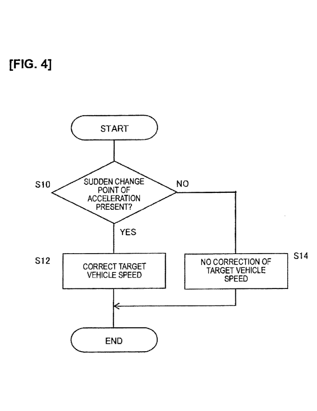
The operations of the sudden change point determination unit 30 (determination
unit) and the
target route calculation unit 32 (correction unit) of the target route
generation ECU 12 according
to the present embodiment will be described, with reference to the flowchart
in Figure 4. The
flowchart of Figure 4 is executed after the target route is updated at each of
the route update
points, as described above.
The sudden change point determination unit 30 determines whether or not a
point at which
there is a sudden change in the acceleration (that is, a point at which the
acceleration changes in
excess of a predetermined condition) is present in the generated target route
(target vehicle
speed) (Step S10). As an example of a predetermined condition that is used to
determine the
presence of a sudden change point in Step SIO, a point at which the
acceleration changes can be
detected in a target vehicle speed pattern, and it can be determined that a
predetermined
condition has been exceeded when the ratio of the acceleration before the
change to the
acceleration after the change, when compared with a predetermined threshold
value, is greater
than the threshold value. Furthermore, for example, even when switching from
acceleration to
deceleration after an idle running period of constant speed driving, if the
period of constant
driving is less than a predetermined period (for example, three seconds), it
can determine that a
CA 02973111 2017-07-05
8
sudden change point is present. If the vehicle decelerates, the sign of
acceleration becomes
negative. A conceivable example of a case in which there is a sudden change in
the acceleration
is a case in which the acceleration of the target route increases due to an
increase in the speed
limit of the driving path, but it is necessary to carry out deceleration
during the acceleration or
immediately after the completion of acceleration, due to the presence of a
stop point (signal, stop
sign, or the like) or a point requiring deceleration (curved path, or the
like) on the drive path
thereafter. An example of the target speed in such a case is illustrated in
the graph of Figure 5.
In Figure 5, the vehicle continues acceleration until time tl and the vehicle
speed reaches VI, but
the vehicle decelerates toward a stop from time tl. Therefore, the time chart
of the target speed
illustrated in Figure 5 has a chevron shape with a pointed tip, having a
sudden change of
acceleration at point P. When such a sudden change of acceleration point P is
present, the
behavior of the vehicle is suddenly switched from acceleration to
deceleration, so there is the
fear of imparting discomfort to the user.
In addition, in Figure 6, the vehicle continues acceleration until time tl and
the vehicle speed
reaches VI; then, after a constant speed driving, the vehicle decelerates
toward a stop from time
tl'. A sudden change of acceleration point P is also present when the period
of this constant
speed driving (period from time tl to time tl') is less than a predetermined
period (for example,
three seconds), and the behavior of the vehicle is suddenly switched from
acceleration to
deceleration, so there is the fear of imparting discomfort to the user.
Therefore, in the present
embodiment, it is also determined that a sudden change of acceleration point P
is present when
the idle running period between acceleration driving and deceleration driving
is less than a
predetermined period, as illustrated in Figure 6.
That is, in the present embodiment, the sudden change point determination unit
30
determines that a sudden change point P is present when the constant speed
driving period
between acceleration driving and deceleration driving, or between deceleration
driving and
acceleration driving, is shorter than a predetermined period, when changing
from acceleration
driving to deceleration driving, or from deceleration driving to acceleration
driving, in the target
vehicle speed. That is, by determining that a sudden change point P is
present, not only when the
constant speed driving period between acceleration driving and deceleration
driving is absent
(when the constant speed driving period is 0), as illustrated in the time
chart of Figure 5, but also
when the constant speed driving period is shorter than a predetermined period
(for example,
Cl. 02973111 2017-07-05
9
three seconds), as illustrated in the graph of Figure 6, it is possible to
reduce the chance that
discomfort is imparted to the user, due to the behavior of the vehicle being
switched relatively
quickly.
Therefore, in the present embodiment, if the sudden change point determination
unit 30
determines that a sudden change of acceleration point P is present on the
target route (YES in
Step S10), the target route calculation unit 32 corrects the target speed of
the target route such
that the sudden change point P is eliminated (Step S12). On the other hand, if
the sudden change
point determination unit 30 determines that a sudden change of acceleration
point is not present
on the target route (NO in Step S10), the target route calculation unit 32
ends the control flow
illustrated in Figure 4, without correcting the target speed of the target
route (Step S14).
That is, the target vehicle speed generation device of a vehicle according to
the present
embodiment comprises a sudden change point determination unit 30
(determination unit) and a
target route calculation unit 32 (correction unit). The sudden change point
determination unit 30
determines whether or not a sudden change point, at which the acceleration
changes suddenly, is
present in the target vehicle speed contained in the target route information
of the vehicle, which
is set in advance. The target route calculation unit 32 corrects the target
vehicle speed so as to
eliminate the sudden change point, if it is determined that a sudden change
point is present by the
sudden change point determination unit 30. Accordingly, it is possible to
reduce discomfort that
is felt by the user, which is caused by a sudden change in the behavior of the
vehicle.
Specifically, in Step S12, the target route calculation unit 32 stops the
acceleration at a
timing that precedes the deceleration start point before correction, and
corrects the target speed
such that deceleration is started after providing a predetermined idle running
period. In the graph
of Figure 7, the target speed illustrated in Figure 5 has been corrected by
the target route
calculation unit 32. Additionally, in Figure 8, the target speed illustrated
in Figure 6 has been
corrected by the target route calculation unit 32. The target speed after
correction is corrected
such that acceleration is stopped at time t2, which is an earlier timing than
time tl, and
deceleration is started from time t3 to stop the vehicle, after carrying out a
constant speed driving
for a predetermined idle running period FP, at a vehicle speed V2, which is
lower than the
vehicle speed VI, as illustrated in Figure 7 and Figure 8. The target route
calculation unit 32 sets
t2 such that the area of portion A and the area of portion A in Figure 7 are
the same, to correct
the target vehicle speed and provide a predetermined idle running period FP,
such that the stop
CA 02973111 2017-07-05
position of the vehicle will be the same as before and after the correction.
By eliminating the
sudden change point P and providing a predetermined idle running period FP in
this manner, it is
possible to smoothly transition from acceleration to deceleration, without
imparting discomfort
to the user. Furthermore, in the example of Figure 8, t3 can be further
provided such that the idle
running period FP becomes a predetermined time or more (for example, three
seconds), after
which the target vehicle speed can be corrected such that the stop position
and the acceleration
will become appropriate values, in order to reduce the discomfort of the user.
That is, in the present embodiment, the target route calculation unit 32
corrects the target
vehicle speed so as to eliminate the sudden change point P, by ending
acceleration or
deceleration at time t2 (second timing), which precedes time ti (first timing)
corresponding to
the sudden change point P, if it is determined that a sudden change point P is
present by the
sudden change point determination unit 30. By eliminating the sudden change
point P and
ending acceleration or deceleration at time t2, which is an earlier timing
than time ti, in this
manner, it is possible to smoothly transition from acceleration driving to
deceleration driving, or,
from deceleration driving to acceleration driving, without imparting
discomfort to the user.
Additionally, in the present embodiment, the target route calculation unit 32
corrects the
target vehicle speed so as to eliminate the sudden change point P, by starting
a predetermined
idle running period FP at time t2 (second timing), which precedes time ti
(first timing)
corresponding to the sudden change point P, if it is determined that a sudden
change point P is
present by the sudden change point determination unit 30. By eliminating the
sudden change
point P and providing a predetermined idle running period FP in this manner,
it is possible to
smoothly transition from acceleration driving to deceleration driving, or from
deceleration
driving to acceleration driving, without imparting discomfort to the user.
Furthermore, in the present embodiment, the sudden change point determination
unit 30
determines whether or not there is a sudden change point P that changes from
acceleration
driving to deceleration driving in the target vehicle speed. The target route
calculation unit 32
corrects the target vehicle speed so as to eliminate the sudden change point
P, by ending
acceleration at a point in time in which the vehicle speed of the vehicle
reaches vehicle speed V2
(second vehicle speed), which is lower than the vehicle speed V1 (first
vehicle speed),
corresponding to the sudden change point P. By ending acceleration before the
vehicle speed is
increased, at a point in time in which the vehicle speed reaches vehicle speed
V2, which is lower
CA 02973111 2017-07-05
ii
than vehicle speed Vi, in this manner, it is possible to smoothly transition
from acceleration
driving to deceleration driving, without imparting discomfort to the user.
Furthermore, in the present embodiment, the sudden change point determination
unit 30
determines whether or not there is a sudden change point P that changes from
acceleration
driving to deceleration driving in the target vehicle speed. The target route
calculation unit 32
corrects the target vehicle speed so as to eliminate the sudden change point
P, by starting
deceleration driving after driving for a predetermined period at vehicle speed
V2 (second vehicle
speed), which is lower than vehicle speed V1 (first vehicle speed),
corresponding to the sudden
change point P. By eliminating the sudden change point P and driving for a
period of time at
vehicle speed V2, which is lower than vehicle speed VI, in this manner, it is
possible to
smoothly transition from acceleration driving to deceleration driving, without
imparting
discomfort to the user.
Here, the predetermined idle running period FP can be set to any appropriate
value, for
example three seconds. In addition, the predetermined idle running period FP
can be set so as to
change according to the acceleration and the vehicle speed.
That is, the target route calculation unit 32 can set the predetermined idle
running period to
be variable, in accordance with at least one of the vehicle speed and
acceleration corresponding
to the sudden change point P. For example, by setting the predetermined idle
running period FP
longer as the acceleration or the vehicle speed is increased, it is possible
to smoothly transition to
acceleration driving or deceleration driving with a sufficient margin, even
when the acceleration
or the vehicle speed is high.
Furthermore, the target route calculation unit 32 can set the time t2 (second
timing) to be
variable, in accordance with at least one of the vehicle speed and
acceleration corresponding to
the sudden change point P. Furthermore, the timing to start the idle running
period FP (time t2)
is preferably set to be an earlier timing, as the acceleration is increased.
By setting the timing to
start the idle running period FP to be earlier as the acceleration is
increased in this manner, it is
possible to start the idle running period FP before the vehicle speed becomes
excessively high,
and to smoothly transition to deceleration, even when the acceleration is
large, and the vehicle
speed will reach a high speed in a short period of time. In addition, in the
examples of Figure 7
and Figure 8, acceleration is ended and constant speed driving at vehicle
speed V2 is started at
the timing of time t2; however, the acceleration can be reduced at the timing
of time t2 such that
CA 02973111 2017-07-05
12
a gentle acceleration driving, or a gentle deceleration driving, is carried
out during the idle
running period FP, or constant speed driving can be carried out until the end
of the idle running
period FP after driving at a small acceleration for a set period. That is, the
vehicle speed control
during the idle running period FP is not limited to constant speed driving, as
long as the target
vehicle speed is such that it is possible to eliminate the sudden change point
P illustrated in
Figure 5 and Figure 6, and to smoothly transition from acceleration to
deceleration.
Examples are described in which the vehicle is ultimately stopped in Figure 5
to Figure 8, but
the same control is also carried out when a deceleration request is output
during acceleration or
immediately after acceleration. An example of a case, in which a deceleration
request is output
during acceleration or immediately after acceleration, is a case in which a
point that requires
deceleration, such as a curve, is present after a point in which the speed
limit of the driving path
is increased.
As described above, in the drive control device according to the first
embodiment, it is
determined whether or not a point at which the acceleration is suddenly
changed is present on the
created target route of the vehicle, and if such a sudden change point is
present, the target speed
is corrected such that the sudden change point is eliminated, and deceleration
is started after a
predetermined idle running period after acceleration. Therefore, it is
possible to avoid imparting
discomfort to the user, which is caused by a sudden change from acceleration
to deceleration, or,
from deceleration to acceleration.
Cases in which the vehicle is accelerating are described in Figure 5 to Figure
8 of the first
embodiment; however, the correction of the target route according to the first
embodiment can
also be applied when the vehicle suddenly changes from deceleration to
acceleration.
(2) Second embodiment
The drive control device 10 according to the second embodiment will be
described, with
further reference to Figure 9 and Figure 10.
In the second embodiment, configurations and steps that function in the same
or similar
manner as in the first embodiment are given the same reference symbols, and
the descriptions
thereof are omitted. The drive control device 10 according to the second
embodiment (refer to
Figure 1) is configured such that, when a vehicle is autonomously driving by
autonomous drive
control, it becomes possible to smoothly switch from acceleration to
deceleration by providing
an idle running period for a predetermined period between acceleration driving
and deceleration
= CA 02973111 2017-07-05
13
driving, if a deceleration instruction or a stop instruction is output during
acceleration or
immediately after acceleration.
Specifically, the drive control device 10 according to the second embodiment
is configured
such that it becomes possible to smoothly switch from acceleration to
deceleration by providing
an idle running period for a predetermined period between acceleration driving
and deceleration
driving, by controlling the sensing sensitivity (detection distance) of the
radar 16 in accordance
with the acceleration of the vehicle (refer to Figure 1).
Figure 9 is a block diagram illustrating the drive control ECU 14 according to
the second
embodiment. The drive control ECU 14 according to the second embodiment
comprises an
acceleration determination unit 34 that determines whether or not the
acceleration of the vehicle
is greater than a predetermined acceleration threshold value, and a detection
distance setting unit
36 that increases the detection distance of the radar 16, if it is determined
that the acceleration of
the vehicle is greater than the predetermined acceleration threshold value by
the acceleration
determination unit 34. In the second embodiment, the acceleration
determination unit 34 further
determines whether or not the speed of the vehicle is greater than a
predetermined speed
threshold value, and the detection distance setting unit 36 increases the
detection distance of the
radar 16, if it is determined that the speed of the vehicle is greater than
the predetermined speed
threshold value.
Figure 10 is a flowchart describing the control of the radar detection
distance according to
the second embodiment. The process indicated in the flowchart of Figure 10 is
repeatedly
executed at predetermined intervals (for example, every 10-50 milliseconds),
at the same time as
starting the autonomous driving of the vehicle.
The acceleration determination unit 34 determines whether or not the
acceleration of the
vehicle exceeds a predetermined acceleration threshold value, from the
detection result of the
driving state detection sensor 20, during autonomous drive control of the
vehicle (Step S20). If
the acceleration exceeds the predetermined acceleration threshold value (YES
in Step S20), next,
it is determined whether or not the vehicle speed exceeds a predetermined
vehicle speed
threshold value (Step S22). If the vehicle speed exceeds the predetermined
vehicle speed
threshold value (YES in Step S22), it is determined that both acceleration and
vehicle speed are
high, and the detection distance of the radar (sensing sensitivity) is
increased by the detection
distance setting unit 36 (Step S24). On the other hand, if the acceleration is
not greater than the
CA 02973111 2017-07-05
14
predetermined threshold value (NO in Step S20), or if the vehicle speed is not
greater than the
predetermined threshold value (NO in Step S22), the control flow illustrated
in Figure 10 is
ended, without correcting the detection distance of the radar 16 (Step S26).
That is, the drive control device of the present embodiment is a drive control
device of a
vehicle that has a distance measurement unit (for example a radar 16) that
measures the distance
to an object to be measured, comprising an acceleration determination unit 34
that determines
whether or not the acceleration of the vehicle is greater than a predetermined
acceleration
threshold value, and a detection distance setting unit 36 that increases the
detection distance of
the distance measurement unit (for example the radar 16), if it is determined
that the acceleration
of the vehicle is greater than the predetermined acceleration threshold value
by the acceleration
determination unit 34. Accordingly, it becomes possible to detect an object to
be measured, such
as a pedestrian or an obstacle, at an early timing, when the acceleration is
high. Accordingly, it
is possible to control the behavior of the vehicle (for example, stop the
acceleration) at an earlier
timing when an object to be measured is present, and to smoothly transition
from acceleration to
deceleration.
Furthermore, the acceleration determination unit 34 according to the present
embodiment
determines whether or not the speed of the vehicle is greater than a
predetermined speed
threshold value, and the detection distance setting unit 36 increases the
detection distance of the
distance measurement unit (for example, the radar 16), if it is determined
that the speed of the
vehicle is greater than the predetermined speed threshold value. Therefore, it
becomes possible
to also detect an object to be measured, such as a pedestrian or an obstacle,
at an early timing,
when the speed of the vehicle is high. Accordingly, it is possible to control
the behavior of the
vehicle (for example, stop the acceleration) at an earlier timing when an
object to be measured is
present, and to smoothly transition from acceleration to deceleration.
Here, the increase in the detection distance by the detection distance setting
unit 36 in Step
S24 can be uniformly set to a predetermined detection distance, or can be
variably set according
to the value of the acceleration and/or the vehicle speed. For example, the
detection distance of
the radar 16 can be set to be greater, as the acceleration and/or the vehicle
speed is increased.
That is, the detection distance setting unit 36 can increase the detection
distance as the
acceleration of the vehicle and/or the speed of the vehicle is increased. By
setting the detection
distance of the radar 16 to be greater as the acceleration and/or the vehicle
speed is increased in
Cl. 02973111 2017-07-05
this manner, it becomes possible to detect an obstacle and start an idle
running period FP before
the vehicle speed becomes excessively high, even when the acceleration is
high, and the vehicle
speed will reach a high speed in a short period of time.
That is, by controlling the detection distance of the radar 16 to be increased
as the
acceleration and the vehicle speed are increased, it becomes possible to
detect obstacles on the
driving path at an earlier timing during acceleration than during non-
acceleration, and it becomes
possible to stop acceleration and provide an idle running period before the
vehicle speed
becomes high.
Here, the control of the second embodiment will be described using the graph
of Figure 7 of
the first embodiment as an example. In Figure 7, if the detection distance of
the radar 16 is 100
m, and it is assumed that an obstacle, etc., that is 100 m ahead is detected
at time ti during
acceleration, a vehicle stop instruction is output at time tl; therefore,
acceleration is suddenly
switched to deceleration at a sudden change point P corresponding to time ti.
In this manner, if
a sudden change point P is present, there is the risk that discomfort is
imparted to the user.
Therefore, in the second embodiment, if the acceleration and vehicle speed
become greater
than their respective threshold values during autonomous drive control, the
detection distance of
the radar 16 is set to, for example, 150 m, which is greater than 100 m.
Accordingly, it becomes
possible to detect an obstacle, etc., at time t2, which is a timing that
precedes time tl of Figure 7.
Therefore, it is possible to stop acceleration at time t2, and to start
deceleration from time 13 to
stop the vehicle, after carrying out a constant speed driving for a
predetermined idle running
period FP, at a vehicle speed V2, which is lower than the vehicle speed Vi.
Accordingly, it is
possible to smoothly transition from acceleration to deceleration. Here, the
predetermined idle
running period FP can be set to any appropriate value, for example three
seconds. In addition,
the predetermined idle running period FP can be set so as to change according
to the acceleration
and the vehicle speed. Additionally, the vehicle speed control during the
predetermined period
FP is not limited to a constant speed driving, in the same manner as the first
embodiment.
Furthermore, an example is described in which the vehicle is ultimately
stopped in Figure 7, but
the same control is also carried out when a deceleration request is output
during acceleration or
immediately after acceleration. An example of a case, in which a deceleration
request is output
during acceleration or immediately after acceleration, is a case in which the
host vehicle
accelerates and approaches a preceding vehicle, in a preceding vehicle
following control.
CA 02973111 2017-07-05
16
Meanwhile, both the control relating to the setting of a target speed when
generating a target
route according to the first embodiment, and the control of the detection
distance of the radar 16
during autonomous drive control according to the second embodiment, can be
carried out as
well. In this case, the drive control device comprises an acceleration
determination unit 34 that
determines whether or not the acceleration of the vehicle is greater than a
predetermined
acceleration threshold value, and a detection distance setting unit 36 that
increases the detection
distance of the distance measurement unit (for example, the radar 16), if it
is determined that the
acceleration of the vehicle is greater than the predetermined acceleration
threshold value by the
acceleration determination unit 34, and is further provided with a target
vehicle speed generation
device, comprising a sudden change point determination unit 30 (determination
unit) that
determines whether or not a sudden change point P at which there is a sudden
change in the
acceleration is present in the target vehicle speed contained in the target
route information of the
vehicle, which is set in advance, and a target route calculation unit 32
(correction unit) that
corrects the target vehicle speed such that the sudden change point P is
eliminated, if the sudden
change point determination unit 30 determines that a sudden change point P is
present.
Accordingly, it becomes possible to further reduce the frequency of occurrence
of a driving
pattern in which a sudden change point P of acceleration is present, and to
reliably avoid
imparting discomfort to the user.
In the first and second embodiments described above, autonomous drive control
is carried out
by the drive control ECU 14; however, the generation of a target route of the
present application
can be used even if a fully autonomous drive control is not carried out, or
even when an
autonomous drive control is not carried out at all. For example, the a target
route generated by
the target route generation ECU 12 can be simply notified to the driver, or
the driving conditions
for achieving the generated target route can be notified to the user. In these
cases, driving
support for supporting the driving of the user (driver) will be carried out
instead of an
autonomous drive control. In addition, even if a fully autonomous drive
control is not carried
out, driving assistance can be carried out, such as carrying out only
acceleration/deceleration or
only steering by the drive control device 10.
[DESCRIPTIONS OF THE REFERENCE SYMBOLS]
Drive control device
12 Target route generation ECU
CA 02973111 2017-07-05
17
14 Drive control ECU
30 Sudden change point determination unit (determination unit)
32 Target route calculation unit (correction unit)
34 Acceleration determination unit
36 Detection distance setting unit