Note: Descriptions are shown in the official language in which they were submitted.
1
SWITCH
FIELD OF THE INVENTION
The present invention relates to a switch configuration for incorporation into
an electronic
device. Aspects of the invention relate to an electronic device including such
a switch. In
particular, the switch is useful in disposable medical devices, for example an
electronic
neurostimulator device.
BACKGROUND TO THE INVENTION
Low cost, disposable electronic devices are used in many fields, including the
medical device
field. The present applicants have previously described an electronic
neurostimulator device,
in international patent application W02010/070332. The device described
therein
incorporates a control unit housing the necessary electronics to drive the
device, and to allow
a user to operate the device; these typically include a PCB and an electrical
cell. A pair of
electrodes driven by the control unit are printed onto a flexible electrically
insulative substrate
(such as BoPET [Biaxially-oriented polyethylene terephthalate], for example
Mylar [RTM])
along with electrically conductive tracks leading to the control unit. The
substrate is mounted
onto a more robust elongate tongue made from, for example, a flexible plastics
material.
Such devices incorporate electrical switches to activate or deactivate the
device, or to allow
a user to adjust the intensity or other characteristics of the electrical
stimulation. Incorporating
suitable switches and their attendant moving parts into a low cost unit can be
problematic,
particularly when the unit is intended to be sealed or disposable. It is among
the objects of
embodiments of the present invention to provide an alternative switch
configuration.
SUMMARY OF THE INVENTION
According to a first aspect of the present invention, there is provided an
electronic device
comprising:
a plastic casing defining an interior and exterior, the interior housing a
printed circuit
board having an electrical contact point, the casing incorporating an external
integral flexible
portion which is capable of being flexed into the interior of the casing;
Date Recue/Date Received 2022-05-11
2
a flexible electrically insulative substrate on which is carried an
electrically conductive
pathway and a pair of electrodes for neuromuscular stimulation; said
electrodes being located
on a portion of said substrate which extends beyond said casing such that the
electrodes are
outside the casing;
wherein at least a portion of the flexible substrate is retained by the casing
such that
said portion is adjacent to but spaced from the PCB;
such that when the integral flexible portion is flexed into the interior of
the casing, it
urges said portion of the flexible substrate into contact with the PCB, such
that the electrically
conductive pathway contacts the electrical contact point, thereby completing
an electrical
circuit; and wherein the flexible substrate and electrically conductive
pathway extend beyond
the casing to drive said electrodes.
This arrangement allows a switch to be formed from a substrate bearing a
printed circuit in
combination with a printed circuit board (PCB) bearing control electronics.
The printed circuit
on the substrate and the PCB are arranged with respect to one another such
that the two are
brought into contact on actuating the integral flexible portion of the casing,
which completes
an electrical circuit. This may be used to activate or deactivate a device, or
to adjust operating
parameters. The switch is relatively inexpensive to produce, as it has few
moving parts, and
can be formed in the usual manufacturing process, and is robust.
In a preferred embodiment, the external integral flexible portion is
resilient, such that when
force is applied to the integral flexible portion it is flexed into the
interior of the casing, and
when force is not applied, it is no longer so flexed. This allows the flexible
portion to act as a
spring, and to reopen the switch after closure. There is thus no need to
include an additional
spring to reopen the switch.
Preferably the external integral flexible portion is formed in a dome shape.
This feature also
gives tactile feedback when pressed. This occurs when the dome is deformed
during
activation. Both the overall form of the dome and the properties of the
polymer help the button
/dome to restructure into its original state.
Date Recue/Date Received 2022-05-11
3
Preferably the portion of the flexible substrate is retained by the casing
under tension. For
example, the flexible substrate may be disposed within a tortuous path formed
within the
casing, such that the substrate is retained by the casing. Keeping the
substrate under tension
also allows the substrate to act somewhat as a spring, as well as retaining it
fast within the
casing to prevent or reduce unwanted movement. The casing may be formed from
two
portions which are secured together (for example, by welding, such as
ultrasonic welding).
and the tortuous path is formed between the two portions.
The extension of the flexible substrate beyond the casing allows electrical
signals to be taken
outside the casing; for example. to drive electrodes mounted beyond the casing
for use as
neuromuscular stimulation devices.
The flexible substrate may be a polymeric substrate, preferably a biaxially-
oriented
polyethylene terephthalate film, for example Mylar (RTM).
The integral flexible portion may comprise an internal protrusion, sized and
shaped to assist
in urging the flexible substrate into contact with the PCB; for example, a pin
or pins extending
from an inner surface of the flexible portion on the casing.
The device may further comprise an electrical cell within the casing.
The device may comprise a plurality of external integral flexible portions,
and a corresponding
plurality of electrical contact points on the PCB that is. The device includes
multiple switches.
Preferably the casing is substantially sealed against moisture ingress.
Preferably the casing is injection moulded.
The device is preferably a medical device, for example an electrical
neuromuscular stimulator.
However, the switch may be incorporated into any number of devices, as will be
readily
apparent to the skilled person.
Date Recue/Date Received 2022-05-11
3a
Also provided by the present invention is an electrical switch comprising:
a plastic casing defining an interior and exterior, the interior housing a
printed circuit
board having an electrical contact point, the casing incorporating an external
integral flexible
portion which is capable of being flexed into the interior of the casing;
a flexible electrically insulative substrate on which is carried an
electrically conductive
pathway;
wherein at least a portion of the flexible substrate is retained by the casing
such that
said portion is adjacent to but spaced from the PCB;
such that when the integral flexible portion is flexed into the interior of
the casing, it
urges said portion of the flexible substrate into contact with the PCB, such
Date Recue/Date Received 2022-05-11
CA 02973173 2017-07-06
WO 2016/110705
PCT/GB2016/050032
4
that the electrically conductive pathway contacts the electrical contact
point, thereby
completing an electrical circuit.
BRIEF DESCRIPTION OF THE FIGURES
Figure 1 shows an electronic neuromuscular stimulation device, taken from
W02010/070332.
Figure 2 shows a section of the control module of a device, incorporating a
switch
arrangement in accordance with an embodiment of the present invention.
Figure 3 shows the control module of Fig 2, when being activated by a user.
Figure 4 shows an enlarged view of a portion of Figure 3.
Figures 5 and 6 show an alternative device.
DETAILED DESCRIPTION OF THE INVENTION
Shown in Figure 1 is a neuromuscular stimulator device 10 as described in
W02010/070332. The device comprises a flexible, non-stretchable thermoplastic
elastomer substrate 12 which includes an elongate tongue 14 at one end, and a
moulded recess 16 at the other.
On the tongue 14 are printed positive 18 and negative 20 electrodes. The
positive is
slightly larger than the negative. Each electrode includes a conductive track
22, 24
leading from the electrode to a respective contact point 26, 28 located in the
recess 16.
Not shown in the figures are an insulative strip arranged between the positive
track 22
and the negative electrode 20, and similar strips at the edges of the tongue,
to prevent
unwanted leakage of current.
Within the recess 16 are placed an electrical cell (not shown), and a PCB (not
shown)
including suitable circuitry to control the electrodes. Together with the
conductive tracks
22, 24 and contact points 26, 28, this forms a complete circuit. A plastic
cover is then
sonically welded over the recess 16 to seal the components, A layer of gel is
then
placed over the whole device 10; this provides an electrical contact with a
user's limb
CA 02973173 2017-07-06
WO 2016/110705
PCT/GB2016/050032
and helps keep the device adhered to a user. The gel may be protected in
transit by a
peelable backing layer.
The outer surface of the recess 16 is formed with an integral diaphragm button
30 and
5 an aperture 32 for displaying an LED. The button 30 is arranged to
contact a
corresponding button on the battery housing or PCB to activate the device. The
aperture 32 displays an LED which indicates whether the device is operating.
In order to incorporate the switch arrangement as described herein, the device
10 is
modified in a number of ways. The positive 18 and negative 20 electrodes are
printed
on a BoPET (eg, Mylar (RIM)) flexible substrate, which is itself affixed to
the elongate
tongue 14. The substrate also carries conductive tracks for connecting the
electrodes
to the control circuitry on the PCB. Further, the button 30 does not itself
contact a
corresponding button on the battery housing or PCB, as will be described.
An alternative device is shown in external view in Figures 5 and 6. This is
generally
similar in operation to the device shown in Figure 1. but has a slightly
different
configuration. in that the recess / enclosure is located towards the centre of
the flexible
tongue. The presence of two dome-shaped push buttons can be seen on the upper
surface of the device, in Figure 5. A view of the device from the lower
surface is shown
in Figure 6.
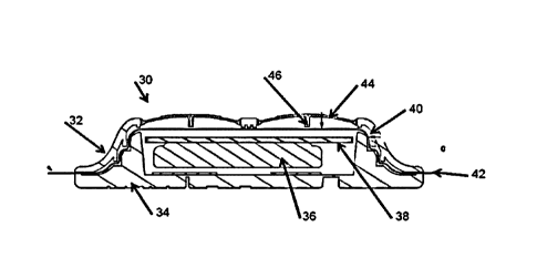
Figure 2 shows a section of the modified device of Figures 5 and 6. in
accordance with
an embodiment of the invention. The figure shows a housing 30 forming an
enclosure
(corresponding to the recess 16 of Figure 1). The housing 30 is formed of two
injection
moulded plastic parts (32, 34), forming upper and lower portions of the
housing. The
elongate tongue 14 can be connected to flanges formed at either end of the
housing
30. Within the housing 30 are located an electrical cell 36 and a PCB 38. The
two
portions of the housing are welded together to form a watertight seal: for
example, by
ultrasonic welding.
The housing 30 includes a tortuous path 40 formed therein between the upper
and
lower portions 32, 34, with the path being formed as a gap between the
portions. Within
this path 40 is placed the Mylar flexible substrate 42, which extends beyond
the
housing where it may be fixed to the tongue 14. On the lower surface (as seen
in the
figure) of the substrate 42 are printed a pair of electrodes and electrically
conductive
CA 02973173 2017-07-06
WO 2016/110705 PCT/G
B2016/050032
6
tracks for connecting the substrate to the PCB 30 and cell 36. The tortuous
path 40
serves to retain the substrate 42 under tension, such that it is suspended
above the
PCB 38, and such that it does not move with respect to the housing.
On the upper external surface of the upper portion 32 of the housing 30 are
formed a
pair of switches in the form of flexible protruding domes 44; each dome 44
includes an
inwardly extending pin 46. The domes 44 and pins 46 are integrally formed
within the
housing. The domes 44 in particular are formed of a resilient material, such
that they
deform under pressure, but return to their original position upon removal of
that
pressure. In some embodiments of the invention, the domes may merely be formed
of
a deformable material, such that they do not revert to their original
position.
In order to actuate the switches, a user will exert pressure on the domes 44
(shown in
Figures 3 and 4) with their finger. The dome 44 deforms and extends inwardly
into the
housing 30; this in turn urges the pin 46 into contact with the substrate 42
which is thus
pressed into contact with the PCB 38. A portion of the conductive track
printed on the
substrate 42 thus contacts a conductive portion formed on the PCB, thereby
forming a
complete electrical circuit and closing the switch. When the user releases the
switch,
the resilience of the plastics material will allow the dome 44 to revert to
the original
position, while the tension in the substrate 42 also assists by acting as a
spring. This
separates the substrate 42 from the PCB 38, thereby opening the switch. The
dome
shape of the switch, in combination with the resilient nature of the substrate
and the
presence of the pin will together provide tactile feedback to the user.
In certain embodiments, the domes 44 may not be resilient, such that the
switch will
remain closed; this might be of use for a single-use button or circuit.
Although the switch has been described in the context of a medical device for
neuromuscular stimulation, it will be apparent that its applicability is not
so limited. In
particular, the switch arrangement it ideally suited for low cost, disposable
applications,
in that there are relatively few moving parts, and the switch can be formed
out of those
components (casing, substrate, PCB) which will be used in an electronic device
anyway. Further, the casing may be sealed to result in a largely waterproof
device. The
present inventors particularly envisage the switch as being of benefit in
mobile
telephones, watches, control panels, or keyboards. among others.