Note: Descriptions are shown in the official language in which they were submitted.
CA 02973388 2017-07-07
WO 2016/112349 PCT/US2016/012744
METHODS AND DEVICES FOR BREAKING CELL AGGREGATION AND
SEPARATING OR ENRICHING CELLS
Cross-Reference to Related Applications
[0001] This application claims priority to U.S. Provisional Application Serial
No. 62/101,938,
filed on January 9, 2015, the content of which is incorporated by reference
herein in its entirety for
all purposes.
Technical Field
[0002] The present invention relates generally to the field of bioseparation,
and in particular to
the field of biological sample processing.
Background
[0003] Sample preparation is a necessary step for many genetic, biochemical,
and biological
analyses of biological and environmental samples. Sample preparation
frequently requires the
separation of sample components of interest from the remaining components of
the sample. Such
separations are often labor intensive and difficult to automate.
[0004] In many cases it is necessary to analyze relatively rare components of
a sample. In this
case, it may be necessary both to increase the concentration of the rare
components to be analyzed,
and to remove undesirable components of the sample that can interfere with the
analysis of the
components of interest. Thus, a sample must be "debulked" to reduce its
volume, and in addition
subjected to separation techniques that can enrich the components of interest.
This is particularly
true of biological samples, such as ascites fluid, lymph fluid, or blood, that
can be harvested in large
amounts, but that can contain minute percentages of target cells (such as
virus-infected cells, anti-
tumor T-cells, inflammatory cells, cancer cells, or fetal cells) whose
separation is of critical
importance for understanding the basis of disease states as well as for
diagnosis and development of
therapies.
[0005] Filtration has been used as a method of reducing the volume of samples
and separating
sample components based on their ability to flow through or be retained by the
filter. Typically
membrane filters are used in such applications in which the membrane filters
have interconnected,
fiber-like, structure distribution and the pores in the membrane are not
discretely isolated; instead
1
CA 02973388 2017-07-07
WO 2016/112349 PCT/US2016/012744
the pores are of irregular shapes and are connected to each other within the
membrane. The so-
called "pore" size really depends on the random tortuosity of the fluid-flow
spaces (e.g., pores) in
the membrane. While the membrane filters can be used for a number of
separation applications, the
variation in the pore size and the irregular shapes of the pores prevent them
being used for precise
filtration based on particle size and other properties.
[0006] Microfabricated filters have been made for certain cellular or
molecular separation
applications. These microfabricated structures do not have pores, but rather
include channels that
are microetched into one or more chips, by using "bricks" (see, for example,
U.S. Patent No.
5,837,115 issued Nov. 17, 1998 to Austin et al., incorporated by reference) or
dams see, for
example, U.S. Patent No. 5,726,026 issued Mar. 10, 1998 to Wilding et al.,
incorporated by
reference) that are built onto the surface of a chip. While these
microfabricated filters have precise
geometries, a limitation is that the filtration area of the filter is small,
limited by the geometries of
these filters, so that these filters can process only small volumes of the
fluid sample.
[0007] Blood samples provide special challenges for sample preparation and
analysis. Blood
samples are easily obtained from subjects, and can provide a wealth of
metabolic, diagnostic,
prognostic, and genetic information. However, the great abundance of non-
nucleated red blood
cells, and their major component hemoglobin, can be an impediment to genetic,
metabolic, and
diagnostic tests. The debulking of red blood cells from peripheral blood has
been accomplished
using different layers of dense solutions (for example, see US patent
5,437,987 issued
August 1, 1995 to Teng, Nelson N.H. et al). Long chain polymers such as
dextran have been used
to induce the aggregation of red blood cells resulting in the formation of
long red blood cell chains
(Sewchand LS, Canham PB. (1979) 'Modes of Rouleaux formation of human red
blood cells in
polyvinylpyrrolidone and dextran solutions' Can. J. Physiol. Pharmacol.
57(11):1213-22).
However, the efficiency of these methods in removing red blood cells is less
than optimal,
especially where the separation or enrichment of rare cells, such as, for
example, fetal cells from
maternal blood or cancer cells from a patient, is desirable. Cell lysis
techniques have also been used
to remove red blood cells. However, the drawbacks of cell lysis techniques
include nonspecific
nucleated cell lysis, red blood cell debris as a result from cell lysis, and
potential cell volume
alteration (Resnitzky P, Reichman N. (1978) 'Osmotic fragility of peripheral
blood lymphocytes in
chronic lymphatic leukemia and malignant lymphoma' Blood 51(4):645-651).
[0008] Exfoliated cells in body fluids (e.g. sputum, urine, or even ascetic
fluid or other
effusions) present a significant opportunity for detection of precancerous
lesions and for eradication
2
CA 02973388 2017-07-07
WO 2016/112349 PCT/US2016/012744
of cancer at early stages of neoplastic development. For example, urine
cytology is universally
accepted as the noninvasive test for the diagnosis and surveillance of
transitional cell carcinoma
(Larsson et al (2001) Molecular Diagnosis 6: 181-188). However, in many cases,
the cytologic
identification of abnormal exfoliated cells has been limited by the number of
abnormal cells
isolated. For routine urine cytology (Ahrendt et al. (1999) J. Natl. Cancer
Inst. 91: 299-301), the
overall sensitivity is less than 50%, which varies with tumor grade, tumor
stage, and urine
collection and processing methods used. Molecular analysis (e.g. using in situ
hybridization, PCR,
microarrays, etc.) of abnormal exfoliated cells in body fluids based on
molecular and genetic
biomarkers can significantly improve the cytology sensitivity. Both biomarker
studies and use of
biomarkers for clinical practice would require a relatively pure exfoliated
cell population enriched
from body fluids comprising not only exfoliated cells but also normal cells,
bacteria, body fluids,
body proteins and other cell debris. Thus, there is an immediate need for
developing an effective
enrichment method for enriching and isolating exfoliated abnormal cells from
body fluids.
[0009] Meye et al., Int. J. Oncol., 21(3):521-30 (2002) describes isolation
and enrichment of
urologic tumor cells in blood samples by a semi-automated CD45 depletion
autoMACS protocol.
Iinuma et al., Int. J. Cancer, 89(4):337-44 (2000) describes detection of
tumor cells in blood using
CD45 magnetic cell separation followed by nested mutant allele-specific
amplification of p53 and
K-ras genes in patients with colorectal cancer. In both studies, tumor cells
were mixed with
mononuclear cells (MNCs) isolated by Ficoll gradient centrifugation from a
blood sample. Tumor
cells were then enriched from MNCs by negative depletion using an anti-CD45
antibody.
[0010] Current approaches for enriching and preparing exfoliated cells from
body fluids, e.g.,
blood samples, use media-based separation, antibody capture, centrifugation
and membrane
filtration. While these techniques are simple and straightforward, they suffer
from a number of
limitations, including: inadequate efficiency for rare cell enrichment; low
sensitivity of rare cell
detection; difficulty in handling large volume samples; inconsistency of the
enrichment
performance; and labor-intensiveness of separation procedure.
[0011] There is a need to provide methods and devices of sample preparation
that are efficient
and/or automatable that can process relatively large sample volumes, such as
large volumes of
biological fluid samples, and separate target cells. The present invention
provides these and other
benefits.
3
CA 02973388 2017-07-07
WO 2016/112349 PCT/US2016/012744
Brief Summary
[0012] In some aspects, the present invention recognizes that diagnosis,
prognosis, and
treatment of many conditions can depend on the enrichment of target cells
and/or cellular
organelles from a complex fluid sample. Often, enrichment can be accomplished
by one or more
separation steps using a filtration device with slots that filter the cells
according to the size, shape,
deformability, binding affinity and/or binding specificity of the cells. For
example, nucleated cells
may be separated from non-nucleated red blood cells in peripheral blood
samples using the
filtration device. In comparison to removal of red blood cells based on cell
lysis techniques, the
filtration device disclosed in the present application may deplete red blood
cells based on their size,
shape, deformability, binding affinity and/or binding specificity, and
minimize loss of nucleated
cells due to nonspecific lysis. Further, it may achieve minimal alteration to
nucleated cell volume
and make a centrifugation step unnecessary.
[0013] In particular, the separation of fetal cells from maternal blood
samples can greatly aid in
the detection of fetal abnormalities or a variety of genetic conditions. In
some aspects, the present
invention recognizes that the enrichment or separation of rare malignant cells
from patient samples,
such as the isolation of cancerous cells from patient body fluid samples, can
aid in the detection and
typing of such malignant cells and therefore aid in diagnosis and prognosis,
as well as in the
development of therapeutic modalities for patients.
[0014] In one aspect, disclosed herein is a method for separating a target
component in a fluid
sample, which method comprises: a) passing a fluid sample that comprises or is
suspected of
comprising a target component and cell aggregates through a microfabricated
filter so that said
target component, if present in said fluid sample, is retained by or passes
through said
microfabricated filter, and b) prior to and/or concurrently with passing said
fluid sample through
said microfabricated filter, contacting said fluid sample with an emulsifying
agent and/or a cellular
cellular membrane charging agent to reduce, remove, and/or disaggregate said
cell aggregates, if
present in said fluid sample.
[0015] In one embodiment, the fluid sample is a blood sample, the target
components are
nucleated cells, the cell aggregates to be reduced or disaggregated are
rouleaux, the fluid sample is
treated with a washing composition comprising one or more emulsifying agent(s)
and/or one or
more cellular membrane charging agent(s), e.g., DMSO and/or pluronic acid,
before and/or during
4
CA 02973388 2017-07-07
WO 2016/112349 PCT/US2016/012744
the filtration step (step a), the red blood cell, platelets and plasma pass
through the microfabricated
filter, and the target nucleated cells are retained by the microfabricated
filter.
[0016] In another embodiment, the fluid sample is a blood sample, the cell
aggregates to be
reduced or disaggregated are rouleaux, the fluid sample is treated with a
washing composition
comprising one or more emulsifying agent(s) and/or one or more cellular
membrane charging
agent(s), e.g., DMSO and/or pluronic acid, before and/or during the filtration
step (step a), the
blood sample passes a first part of the microfabricated filter to produce a
first filtrate that is
substantially cleared of the red blood cell, platelets and plasma, the first
filtrate then passes the
second part of the microfabricated filter that allows the nucleated cells or
other smaller cells, e.g.,
lymphocytes and monocytes, to pass through, while retaining larger cells or
cell aggregates, e.g.,
doublets of cells. In one aspect, the nucleated cells or other smaller cells
that pass through the
second part of the microfabricated filter are collected via a separate
pathway.
[0017] In yet another aspect, the fluid sample is a blood sample, the cell
aggregates to be
reduced or disaggregated are rouleaux, the fluid sample is treated with a
washing composition
comprising one or more emulsifying agent(s) and/or one or more cellular
membrane charging agent
(s), e.g., DMSO and/or pluronic acid, before and/or during the filtration step
(step a), a filtration
device comprising a first and a second microfabricated filters, a sample feed
channel and a recovery
chamber is used, the first microfabricated filter being located above the
sample feed channel,
having a non-stick surface and having a pore size smaller than about 5iim, and
the second
microfabricated filter being located below the sample feed channel, the first
microfabricated filter
being used to maintain a continuous current of flow of a wash buffer across
both microfabricated
filters such that when the blood sample is fed through the feed channel and
into the recovery
chamber, all smaller particles, e.g., RBC, are caught in the cross current and
removed from the
blood sample. Exemplary filtration devices are shown in Figures 33-38.
[0018] In any of the preceding embodiments, the method can further comprise
before the steps
a) and/or b), passing the fluid sample through a prefilter that retains
aggregated cells and
microclots, and allows single cells and smaller particles with a diameter
smaller than about 20iim to
pass through to generate a pre-treated fluid sample that is subject to the
steps a) and/or b)
subsequently. In one aspect, the method further comprises before passing the
fluid sample through
the prefilter, treating the fluid sample with a cell aggregation agent to
aggregate red blood cells, and
removing the aggregated red blood cells. In a further aspect, the cell
aggregation agent is a dextran,
dextran sulfate, dextran or dextran sulfate with a molecular weight less than
about 15kD, hetastarch,
CA 02973388 2017-07-07
WO 2016/112349 PCT/US2016/012744
gelatin, pentastarch, poly ethylene glycol (PEG), fibrinogen, gamma globulin,
hespan, pentaspan,
hepastarch, ficoll, gum arabic, poyvinylpyrrolidone, or any combination
thereof. In another aspect,
the aggregated red blood cells are removed via sedimentation or laminar flow
or a combination
thereof.
[0019] In any of the preceding embodiments, the fluid sample can be separated
based on the
size, shape, deformability, binding affinity and/or binding specificity of the
components, e.g., the
target component, cells and cell aggregates, in the fluid sample.
[0020] In any of the preceding embodiments, the fluid sample can be
manipulated by a
physical force effected via a structure that is external to the
microfabricated filter and/or a structure
that is built-in on the microfabricated filter. In one embodiment, the
physical force is selected from
the group consisting of a dielectrophoretic force, a traveling-wave
dielectrophoretic force, a
magnetic force, an acoustic force, an electrostatic force, a mechanical force,
an optical radiation
force and a thermal convection force. In one aspect, the dielectrophoretic
force or the traveling-
wave dielectrophoretic force is effected via an electrical field produced by
an electrode. In some
aspects, the acoustic force is effected via a standing-wave acoustic field or
a traveling-wave
acoustic field, via an acoustic field produced by piezoelectric material,
and/or via a voice coil or
audio speaker, or a combination thereof. In one aspect, the electrostatic
force is effected via a direct
current (DC) electric field. In another aspect, the optical radiation force is
effected via laser
tweezers.
[0021] In any of the preceding embodiments, the target component can be a
cell, a sub-cellular
structure or a virus in the fluid sample.
[0022] In any of the preceding embodiments, the fluid sample can comprise
blood, effusion,
urine, bone marrow sample, ascitic fluid, pelvic wash fluid, pleural fluid,
spinal fluid, lymph,
serum, mucus, sputum, saliva, semen, ocular fluid, extract of nasal, throat or
genital swab, cell
suspension from digested tissue, extract of fecal material, cultured cells of
either mixed types and/or
mixed sizes, or cells that contain contaminants or unbound reactants that need
to be removed. In
one aspect, the fluid sample is a blood sample and the component being removed
is a plasma, a
platelet and/or a red blood cell (RBC).
[0023] In another aspect, the fluid sample comprises cells that contain
contaminants or
unbound reactants that need to be removed. In one embodiment, the reactant is
a labeling reagent
for the cells. In another embodiment, the reactant is a soluble or dissolved
antigen or molecule that
may compete for or interfere with downstream analyses. In another embodiment,
the fluid sample
6
CA 02973388 2017-07-07
WO 2016/112349 PCT/US2016/012744
is a blood sample and the target component is a nucleated cell. In one aspect,
the nucleated cell is a
non-hematopoietic cell, a subpopulation of blood cells, a fetal red blood
cell, a stem cell, or a
cancerous cell. In another aspect, the fluid sample is an effusion or a urine
sample and the target
component is a nucleated cell. In still another aspect, the nucleated cell is
a cancerous cell or a non-
hematopoietic cell.
[0024] In any of the preceding embodiments, the fluid sample can be blood and
the cell
aggregates to be reduced, removed, and/or disaggregated can be rouleaux, i.e.,
stacks or aggregates
of red blood cells.
[0025] In any of the preceding embodiments, the target component can be
retained by the
microfabricated filter. In any of the preceding embodiments, the target
component can pass
through the microfabricated filter.
[0026] In any of the preceding embodiments, the method can comprise, prior to
passing the
fluid sample through the microfabricated filter, contacting the fluid sample
with an emulsifying
agent and/or a cellular membrane charging agent.
[0027] In any of the preceding embodiments, the method can comprise,
concurrently with
passing the fluid sample through the microfabricated filter, contacting the
fluid sample with an
emulsifying agent and/or a cellular membrane charging agent.
[0028] In any of the preceding embodiments, the method can comprise, prior to
and
concurrently with passing the fluid sample through the microfabricated filter,
contacting the fluid
sample with an emulsifying agent and/or a cellular membrane charging agent. In
one embodiment,
prior to passing the fluid sample through the microfabricated filter, the
emulsifying agent and/or a
cellular membrane charging agent is used at a first level, and concurrently
with passing the fluid
sample through the microfabricated filter, the emulsifying agent and/or a
cellular membrane
charging agent is used at a second level, and the first level is higher than
the second level.
[0029] In any of the preceding embodiments, the emulsifying agent and/or a
cellular membrane
charging agent can be used at a level ranging from about 1 mg/mL to about 300
mg/mL, or from
about 0.01% (v/v) to about 15% (v/v).
[0030] In any of the preceding embodiments, the emulsifying agent can be a
synthetic
emulsifier, a natural emulsifier, a finely divided or finely dispersed solid
particle emulsifier, an
auxiliary emulsifier, a monomolecular emulsifier, a multimolecular emulsifier,
or a solid particle
film emulsifier. In one aspect, the synthetic emulsifier is a cationic, an
anionic or a nonionic agent.
In another aspect, the cationic emulsifier is benzalkonium chloride or
benzethonium chloride. In
7
CA 02973388 2017-07-07
WO 2016/112349 PCT/US2016/012744
one embodiment, the anionic emulsifier is an alkali soap, e.g., sodium or
potassium oleate, an
amine soap, e.g., triethanolamine stearate, or a detergent, e.g., sodium
lauryl sulfate, sodium dioctyl
sulfosuccinate, or sodium docusate. In other embodiments, the nonionic
emulsifier can be a
sorbitan ester, e.g., Spans , a polyoxyethylene derivative of sorbitan ester,
e.g., Tweens , or a
glyceryl ester.
[0031] In some embodiments, the natural emulsifier is a vegetable derivative,
an animal
derivative, a semi-synthetic agent or a synthetic agent. In one aspect, the
vegetable derivative is
acacia, tragacanth, agar, pectin, carrageenan, or lecithin. In another aspect,
the animal derivative is
gelatin, lanolin, or cholesterol. In still another aspect, the semi-synthetic
agent is methylcellulose or
carboxymethylcellulose. In one embodiment, the synthetic agent is Carbopols .
[0032] In other embodiments, the finely divided or finely dispersed solid
particle emulsifier is
bentonite, veegum, hectorite, magnesium hydroxide, aluminum hydroxide or
magnesium trisilicate.
[0033] In some embodiments, the auxiliary emulsifier is a fatty acid, e.g.,
stearic acid, a fatty
alcohol, e.g., stearyl or cetyl alcohol, or a fatty ester, e.g., glyceryl
monostearate.
[0034] In any of the preceding embodiments, the emulsifying agent can have a
hydrophile-
lipophile balance (HLB) value from about 1 to about 40.
[0035] In any of the preceding embodiments, the emulsifying agent can be
selected from the
group consisting of PEG 400 Monoleate (polyoxyethylene monooleate), PEG 400
Monostearate
(polyoxyethylene monostearate), PEG 400 Monolaurate (polyoxyethylene
monolaurate), potassium
oleate, sodium lauryl sulfate, sodium oleate, Span 20 (sorbitan monolaurate),
Span 40 (sorbitan
monopalmitate), Span 60 (sorbitan monostearate), Span 65 (sorbitan
tristearate), Span 80
(sorbitan monooleate), Span 85 (sorbitan trioleate), triethanolamine oleate,
Tween 20
(polyoxyethylene sorbitan monolaurate), Tween 21 (polyoxyethylene sorbitan
monolaurate),
Tween 40 (polyoxyethylene sorbitan monopalmitate), Tween 60 (polyoxyethylene
sorbitan
monostearate), Tween 61 (polyoxyethylene sorbitan monostearate), Tween 65
(polyoxyethylene sorbitan tristearate), Tween 80 (polyoxyethylene sorbitan
monooleate),
Tween 81 (polyoxyethylene sorbitan monooleate) and Tween 85 (polyoxyethylene
sorbitan
trioleate).
[0036] In any of the preceding embodiments, the emulsifying agent can be a
pluronic acid or an
organosulfur compound. In one aspect, the pluronic acid is Pluronic 10R5,
Pluronic 17R2,
Pluronic 17R4, Pluronic 25R2, Pluronic 25R4, Pluronic 31R1, Pluronic F-
108, Pluronic
F-108NF, Pluronic F-108 Pastille, Pluronic F-108NF Prill Poloxamer 338,
Pluronic F-127
8
CA 02973388 2017-07-07
WO 2016/112349 PCT/US2016/012744
NF, Pluronic F-127NF 500 BHT Prill, Pluronic F-127NF Prill Poloxamer 407,
Pluronic F 38,
Pluronic F 38 Pastille, Pluronic F 68, Pluronic F 68 NF, Pluronic F 68 NF
Prill Poloxamer
188, Pluronic F 68 Pastille, Pluronic F 77, Pluronic F 77 Micropastille,
Pluronic F 87,
Pluronic F 87 NF, Pluronic F 87 NF Prill Poloxamer 237, Pluronic F 88,
Pluronic F 88
Pastille, Pluronic FT L 61, Pluronic L 10, Pluronic L 101, Pluronic L 121,
Pluronic L 31,
Pluronic L 35, Pluronic L 43, Pluronic L 61, Pluronic L 62, Pluronic L 62
LF, Pluronic
L 62D, Pluronic L 64, Pluronic L 81, Pluronic L 92, Pluronic L44 NF INH
surfactant
Poloxamer 124, Pluronic N 3, Pluronic P 103, Pluronic P 104, Pluronic P
105, Pluronic P
123 Surfactant, Pluronic P 65, Pluronic P 84, Pluronic P 85, or any
combination thereof. In
another aspect, the pluronic acid is used at a level ranging from about 1
mg/mL to about 300
mg/mL, from about 1 mg/mL to about 200 mg/mL, from about 5 mg/mL to about 50
mg/mL, from
about 5 mg/mL to about 15 mg/mL, or from about 15 mg/mL to about 50 mg/mL. In
particular
embodiments, the pluronic acid is used at about 15 mg/mL. In yet another
aspect, the organosulfur
compound is dimethyl sulfoxide (DMSO). In one embodiment, the DMSO is used at
a level
ranging from about 0.01% (v/v) to about 15% (v/v), from about 0.02% (v/v) to
about 0.4% (v/v), or
from about 0.01% (v/v) to about 0.5% (v/v). In one embodiment, the DMSO is
used at about 0.1%
(v/v). In another embodiment, the DMSO is used at about 0.5% (v/v).
[0037] In any of the preceding embodiments, at least two different emulsifying
agents can be
used, or at least two cellular membrane charging agents can be used, or at
least one emulsifying
agent and at least one cellular membrane charging agent can be used. In one
embodiment, a
pluronic acid and DMSO are used.
[0038] In any of the preceding embodiments, the method can further comprise:
c) rinsing the
retained target component of the fluid sample with an additional sample-free
rinsing reagent.
[0039] In any of the preceding embodiments, the method can further comprise:
d) providing a
labeling reagent to bind to the target component. In one aspect, the labeling
reagent is an antibody.
In another aspect, the method can further comprise: e) removing the unbound
labeling reagent.
[0040] In any of the preceding embodiments, the method can further comprise:
f) recovering
the target component in a collection device.
[0041] In any of the preceding embodiments, the method can further comprise
removing at
least one type of undesirable component using a specific binding member from
the fluid sample. In
one embodiment, the fluid sample is a blood sample. In one aspect, the at
least one undesirable
component are white blood cells (WBCs). In another aspect, the specific
binding member
9
CA 02973388 2017-07-07
WO 2016/112349 PCT/US2016/012744
selectively binds to WBCs and is coupled to a solid support. In yet another
aspect, the specific
binding member is an antibody or an antibody fragment that selectively binds
to WBCs. In some
embodiments, the specific binding member can be an antibody that selectively
binds to CD3,
CD11b, CD14, CD17, CD31, CD35, CD45, CD50, CD53, CD63, CD69, CD81, CD84,
CD102,
and/or CD166. In particular embodiments, the specific binding member is an
antibody that
selectively binds to CD35 and/or CD50.
[0042] In any of the preceding embodiments, the method can further comprise
contacting the
blood sample with a secondary specific binding member. In one aspect, the
secondary specific
binding member is an antibody that selectively binds to CD31, CD36, CD41, CD42
(a, b or c),
CD51, and/or CD51/61.
[0043] In any of the preceding embodiments, the fluid sample can be a blood
sample, the target
components can be nucleated cells, the cell aggregates to be reduced, removed,
and/or
disaggregated can be rouleaux, the fluid sample can be treated with a washing
composition
comprising one or more emulsifying agent(s) and/or one or more cellular
membrane charging
agent(s), e.g., DMSO and/or pluronic acid, before and/or during the filtration
step (step a), the red
blood cell, platelets and plasma can pass through the microfabricated filter,
and the target nucleated
cells can be retained by the microfabricated filter.
[0044] In any of the preceding embodiments, the fluid sample can be a blood
sample, the cell
aggregates to be reduced, removed, and/or disaggregated can be rouleaux, the
fluid sample can be
treated with a washing composition comprising one or more emulsifying agent(s)
and/or one or
more cellular membrane charging agent(s), e.g., DMSO and/or pluronic acid,
before and/or during
the filtration step (step a), the blood sample can pass a first part of the
microfabricated filter to
produce a first filtrate that is substantially cleared of the red blood cell,
platelets and plasma, the
first filtrate can then pass the second part of the microfabricated filter
that allows the nucleated cells
or other smaller cells, e.g., lymphocytes and monocytes, to pass through,
while retaining larger cells
or cell aggregates, e.g., doublets of cells. In one aspect, the nucleated
cells or other smaller cells
that pass through the second part of the microfabricated filter are collected
via a separate pathway.
[0045] In any of the preceding embodiments, the fluid sample can be a blood
sample, the cell
aggregates to be reduced, removed, and/or disaggregated can be rouleaux, the
fluid sample can be
treated with a washing composition comprising one or more emulsifying agent(s)
and/or one or
more cellular membrane charging agent(s), e.g., DMSO and/or pluronic acid,
before and/or during
the filtration step (step a), a filtration device comprising a first and a
second microfabricated filters,
CA 02973388 2017-07-07
WO 2016/112349 PCT/US2016/012744
a sample feed channel and a recovery chamber can be used, the first
microfabricated filter being
located above the sample feed channel, having a non-stick surface and having a
pore size smaller
than about 5i.tm, and the second microfabricated filter being located below
the sample feed channel,
the first microfabricated filter being used to maintain a continuous current
of flow of a wash buffer
across both microfabricated filters such that when the blood sample is fed
through the feed channel
and into the recovery chamber, all smaller particles, e.g., RBC, are caught in
the cross current and
removed from the blood sample.
[0046] In any of the preceding embodiments, the method can further comprise
before the steps
a) and/or b), passing the fluid sample through a prefilter that retains
aggregated cells and
microclots, and allows single cells and smaller particles with a diameter
smaller than about 20iim to
pass through to generate a pre-treated fluid sample that is subject to the
steps a) and/or b)
subsequently. In one aspect, the method further comprises before passing the
fluid sample through
the prefilter, treating the fluid sample with a cell aggregation agent to
aggregate red blood cells, and
removing the aggregated red blood cells. In another aspect, the cell
aggregation agent is a dextran,
dextran sulfate, dextran or dextran sulfate with a molecular weight less than
about 15kD, hetastarch,
gelatin, pentastarch, poly ethylene glycol (PEG), fibrinogen, gamma globulin,
hespan, pentaspan,
hepastarch, ficoll, gum arabic, poyvinylpyrrolidone, or any combination
thereof. In yet another
aspect, the aggregated red blood cells are removed via sedimentation or
laminar flow or a
combination thereof.
[0047] In any of the preceding embodiments, the fluid sample can be separated
based on the
size, shape, deformability, binding affinity and/or binding specificity of the
components, e.g., the
target component, cells and cell aggregates, in the fluid sample.
[0048] In another aspect, provided herein is a method according to any one of
preceding
embodiments, wherein the microfabricated filter is comprised in a filtration
chamber according to
any one of embodiments 1-80, and which method comprises: a) dispensing the
fluid sample into the
filtration chamber according to any one of embodiments 1-80; and b) providing
a fluid flow of the
fluid sample through the filtration chamber, wherein the target component of
the fluid sample is
retained by or passes through the microfabricated filter. In one aspect, the
method further
comprises providing a fluid flow of the fluid sample through the antechamber
of the filtration
chamber and a fluid flow of a solution through the post-filtration subchamber
of the filtration
chamber, and optionally a fluid flow of a solution through the suprachamber of
the filtration
chamber.
11
CA 02973388 2017-07-07
WO 2016/112349 PCT/US2016/012744
[0049] In any of the preceding embodiments, the fluid sample can be separated
based on the
size, shape, deformability, binding affinity and/or binding specificity of the
components in the fluid
sample. In one aspect, the fluid sample is dispensed through the inflow port
of the antechamber.
[0050] In any of the preceding embodiments, the solution can be introduced to
the inflow port
of the post-filtration subchamber.
[0051] In any of the preceding embodiments, the solution can be introduced to
the inflow port
of the supra-filtration chamber.
[0052] In still another aspect, provided herein is a method according to any
one of preceding
embodiments, wherein the microfabricated filter is comprised in an automated
filtration unit
according to any one of embodiments 84-99, and which method comprises: a)
dispensing the fluid
sample into the filtration chamber in the automated filtration unit according
to any one of
embodiments 84-99; and b) providing a fluid flow of the fluid sample through
the filtration
chamber, wherein the target component of the fluid sample is retained by or
flows through the
microfabricated filter. In one aspect, the fluid sample is separated based on
the size, shape,
deformability, binding affinity and/or binding specificity of the components
in the fluid sample.
[0053] In any of the preceding embodiments, the fluid sample in the
antechamber can flow
substantially anti-parallel to the solution in the post-filtration subchamber.
[0054] In any of the preceding embodiments, the filter rate can be about 0-5
mL/min. In one
embodiment, the filter rate is about 10-500 .tt/min. In another embodiment,
the filter rate is about
80-140 lL/min.
[0055] In any of the preceding embodiments, the feed rate can be about 1-10
times the filter
rate.
[0056] In any of the preceding embodiments, the method can further comprise:
c) rinsing the
retained components of the fluid sample with an additional sample-free rinsing
reagent. In one
aspect, during the rinsing step, the feed rate is less than or equal to the
filter rate. In any of the
preceding embodiments, a rinsing reagent can be introduced to the post-
filtration subchamber. In
any of the preceding embodiments, a rinsing reagent can be introduced to the
antechamber and/or
the suprachamber.
[0057] In any of the preceding embodiments, the method can further comprise:
d) providing a
labeling reagent to bind to the target component. In one aspect, the labeling
reagent is an antibody.
In any of the preceding embodiments, the labeling reagent can be added to the
collection chamber.
12
CA 02973388 2017-07-07
WO 2016/112349 PCT/US2016/012744
In any of the preceding embodiments, the labeling reagent can be added to the
antechamber and/or
the suprachamber.
[0058] In any of the preceding embodiments, during the labeling step, the
fluid flow in the
post-filtration subchamber can be stopped.
[0059] In any of the preceding embodiments, the method can further comprise:
e) removing the
unbound labeling reagent.
[0060] In any of the preceding embodiments, the method can further comprise:
f) recovering
the target component in the collection chamber. In one aspect, during the
recovering step, the feed
rate is about 5-20 mL/min. In any of the preceding embodiments, during the
recovering step, the
outflow rate can equal the inflow rate in the post-filtration subchamber. In
any of the preceding
embodiments, during the recovering step, the outflow can be paused for about
50 ms.
[0061] In any of the preceding embodiments, the microfabricated filter can be
comprised in the
automated system according to embodiments 100 or 101, and which method can
comprise: a)
dispensing the fluid sample into the filtration chamber in an automated system
according to
embodiments 100 or 101; b) providing a fluid flow of the fluid sample through
the antechamber of
the filtration chamber and a fluid flow of a solution through the post-
filtration subchamber of the
filtration chamber, wherein the target component of the fluid sample is
retained in the antechamber
and non-target components flow through the filter into the post-filtration
subchamber; c) labeling
the target component; and d) analyzing the labeled target component using the
analysis apparatus.
In one aspect, the method further comprises providing fluid flow into the
suprachamber.
[0062] In any of the preceding embodiments, the target component can be a cell
or cellular
organelle. In one embodiment, the cell is a nucleated cell. In another
embodiment, the cell is a rare
cell. Thus, in any of the preceding embodiments, the cellular membrane
charging agent may be an
agent that confers charges to the cell membrane, the plasma membrane, or
membrane of a cellular
organelle.
[0063] In still another embodiment, provided herein is a device, system or
package for
separating a target component in a fluid sample that comprises or is suspected
of comprising a
target component and cell aggregates, which device, system or package
comprises: a) a filtration
chamber according to any one of embodiments 1-80; and b) an effective amount
of an emulsifying
agent and/or a cellular membrane charging agent to reduce, remove, and/or
disaggregate said cell
aggregates, if present in said fluid sample.
13
CA 02973388 2017-07-07
WO 2016/112349 PCT/US2016/012744
[0064] In yet another embodiment, provided herein is a device, system or
package for
separating a target component in a fluid sample that comprises or is suspected
of comprising a
target component and cell aggregates, which device, system or package
comprises: a) a cartridge
according to any one of embodiments 81-83; and b) an effective amount of an
emulsifying agent
and/or a cellular membrane charging agent to reduce, remove, and/or
disaggregate said cell
aggregates, if present in said fluid sample.
[0065] In one embodiment, provided herein is a device, system or package for
separating a
target component in a fluid sample that comprises or is suspected of
comprising a target component
and cell aggregates, which device, system or package comprises: a) an
automated filtration unit
according to any one of embodiments 84-99; and b) an effective amount of an
emulsifying agent
and/or a cellular membrane charging agent to reduce or disaggregate said cell
aggregates, if present
in said fluid sample; and/or, a hyperosmotic saline solution between about 300
mOsm and about
1000 mOsm, optionally between about 350 mOsm and about 1000 mOsm, between
about 350
mOsm and about 600 mOsm, between about 400 mOsm and about 600 mOsm, between
about 450
mOsm and about 600 mOsm, or between about 550 mOsm and about 600 mOsm, to
reduce or
disaggregate said cell aggregates, if present in said fluid sample.
[0066] In one embodiment, provided herein is a system or package for
separating a target
component in a fluid sample that comprises or is suspected of comprising a
target component and
cell aggregates, which system or package comprises: a) an automated system
according to
embodiments 100 or 101; and b) an effective amount of an emulsifying agent
and/or a cellular
membrane charging agent to reduce or disaggregate said cell aggregates, if
present in said fluid
sample; and/or, a hyperosmotic saline solution between about 300 mOsm and
about 1000 mOsm,
optionally between about 350 mOsm and about 1000 mOsm, between about 350 mOsm
and about
600 mOsm, between about 400 mOsm and about 600 mOsm, between about 450 mOsm
and about
600 mOsm, or between about 550 mOsm and about 600 mOsm, to reduce or
disaggregate said cell
aggregates, if present in said fluid sample.
Brief Description of the Figures
[0067] FIG. 1 is the top view of a region of a microfabricated chip of an
exemplary
embodiment of the present invention. The dark areas are the precision
manufactured slots in the
filter that has a filtration area of 1 cm2.
14
CA 02973388 2017-07-07
WO 2016/112349 PCT/US2016/012744
[0068] FIG. 2 is a schematic representation of a microfabricated filter of an
exemplary
embodiment of the present invention. A) the top view, showing an 18 x 18 mm2
microfabricated
filter having a filtration area (1) of 10 x 10 mm2. B) an enlargement of a
section of the top view,
showing the slots (2) having dimensions of 4 microns x 50 microns, with the
center to center
distance between slots of 12 microns, and their parallel alignment. C) a cross-
sectional view of the
microfabricated filter, with the slots extending through the filter substrate.
[0069] FIG. 3 depicts filters of an exemplary embodiment of the present
invention having
electrodes incorporated into their surfaces. A) a 20-fold magnification of a
portion of a
microfabricated filter having 2 micron slot widths. B) a 20-fold magnification
of a portion of a
microfabricated filter having 3 micron slot widths.
[0070] FIG. 4 depicts a cross section of a pore in a microfabricated filter of
an exemplary
embodiment of the present invention. The pore depth corresponds to the filter
thickness. Y
represents the right angle between the surface of the filter and the side of a
pore cut perpendicularly
through the filter, while X is the tapering angle by which a tapered pore
differs in its direction or
orientation through the filter from a non-tapered pore.
[0071] FIG. 5 depicts a filtration unit of an exemplary embodiment of the
present invention
having a microfabricated filter (3) separating the filtration chamber into an
upper antechamber (4)
and a post-filtration subchamber (5). The unit has valves to control fluid
flow into and out of the
unit: valve A (6) controls the flow of sample from the loading reservoir (10)
into the filtration unit,
valve B (7) controls fluid flow through the chamber by connection to a syringe
pump, and valve C
(8) is used for the introduction of wash solution into the chamber.
[0072] FIG. 6 is a diagram of an automated system of an exemplary embodiment
of the present
invention that comprises an inlet for the addition of a blood sample (11); a
filtration chamber (12)
that comprises acoustic mixing chips (13) and microfabricated filters (103); a
magnetic capture
column (14) having adjacent magnets (15); a mixing/filtration chamber (112); a
magnetic
separation chamber (16) comprising an electromagnetic chip (17), and a vessel
for rare cell
collection (18).
[0073] FIG. 7 depicts a three-dimensional perspective view of a filtration
chamber of an
exemplary embodiment of the present invention that has two filters (203) that
comprise slots (202)
and a chip having acoustic elements (200) (the acoustic elements may not be
visible on the chip
surface, but are shown here for illustrative purposes). In this simplified
depiction, the width of the
slots is not shown.
CA 02973388 2017-07-07
WO 2016/112349 PCT/US2016/012744
[0074] FIG. 8 depicts a cross-sectional view of a filtration chamber of an
exemplary
embodiment of the present invention having two filters (303) after filtering
has been completed,
and after the addition of magnetic beads (19) to a sample comprising target
cells (20). The acoustic
elements are turned on during a mixing operation.
[0075] FIG. 9 depicts a cross-sectional view of a feature of an automated
system of an
exemplary embodiment of the present invention: a magnetic capture column
(114). Magnets (115)
are positioned adjacent to the separation column.
[0076] FIG. 10 depicts a three-dimensional perspective view of a chamber (416)
of an
automated system of an exemplary embodiment of the present invention that
comprises a multiple
force chip that can separate rare cells from a fluid sample. The chamber has
an inlet (429) and an
outlet (430) for fluid flow through the chamber. A cut-away view shows the
chip has an electrode
layer (427) that comprises an electrode array for dielectrophoretic separation
and an
electromagnetic layer (417) that comprises electromagnetic units (421) an
electrode array on
another layer. Target cells (420) are bound to magnetic beads (419) for
electromagnetic capture.
[0077] FIG. 11 shows a graph illustrating the theoretical comparison between
the DEP spectra
for an nRBC (Xs) and a RBC (circles) when the cells are suspended in a medium
of electrical
conductivity of 0.2 S/m.
[0078] FIG. 12 shows FISH analysis of nucleated fetal cells isolated using the
methods of an
exemplary embodiment of the present invention using a Y chromosome marker that
has detected a
male fetal cell in a maternal blood sample.
[0079] FIG. 13 shows a process flow chart for enriching fetal nucleated RBCs
from maternal
blood.
[0080] FIG. 14 is a schematic depiction of a filtration unit of an exemplary
embodiment of the
present invention.
[0081] FIG. 15 shows a model of an automated system of an exemplary embodiment
of the
present invention.
[0082] FIG. 16 depicts the filtration process of an automated system of an
exemplary
embodiment of the present invention. A) shows the filtration unit having a
loading reservoir (510)
connected through a valve (506) to a filtration chamber that comprises an
antechamber (504)
separated from a post-filtration subchamber (505) by a microfabricated filter
(503). A wash pump
(526) is connected to the lower chamber through a valve (508) for pumping wash
buffer (524)
through the lower subchamber. Another valve (507) leads to another negative
pressure pump used
16
CA 02973388 2017-07-07
WO 2016/112349 PCT/US2016/012744
to promote fluid flow through the filtration chamber and out through an exit
conduit (530). A
collection vessel (518) can reversibly engage the upper chamber (504). B)
shows a blood sample
(525) loaded into the loading reservoir (510). In C) the valve (507) that
leads to a negative pressure
pump used to promote fluid flow through the filtration chamber is open, and D)
and E) show the
blood sample being filtered through the chamber. In F) wash buffer introduced
through the loading
reservoir is filtered through the chamber. In G), valve (508) is open, while
the loading reservoir
valve (506) is closed, and wash buffer is pumped from the wash pump (526) into
the lower
chamber. In H) the filtration valve (507) and wash pump valve (508) are closed
and in I) and J) the
chamber is rotated 90 degrees. K) shows the collection vessel (518) engaging
the antechamber
(504) so that fluid flow generated by the wash pump (526) causes rare target
cells (520) retained in
the antechamber to flow into the collection tube.
[0083] FIG. 17 depicts a fluorescently labeled breast cancer cell in a
background of unlabeled
blood cells after enrichment by microfiltration. A) phase contrast microscopy
of filtered blood
sample. B) fluorescence microscopy of the same field shown in A.
[0084] FIG. 18 depicts two configurations of dielectrophoresis chips of an
exemplary
embodiment of the present invention. A) chip with interdigitated electrode
geometry; B) chip with
castellated electrode geometry.
[0085] FIG. 19 depicts a separation chamber of an exemplary embodiment of the
present
invention comprising a dielectrophoresis chip. A) Cross-sectional view of the
chamber, B) top view
showing the chip.
[0086] FIG. 20 is a graph illustrating the theoretical comparison between the
DEP spectra for
MDA231 cancer cells (solid line) T-lymphocytes (dashed line) and erythrocytes
(small dashes)
when the cells are suspended in a medium of electrical conductivity of 10
mS/m.
[0087] FIG. 21 A and B depict breast cancer cells from a spiked blood sample
retained on
electrodes of an exemplary dielectrophoresis chip.
[0088] FIG. 22 depicts white blood cells of a blood sample retained on
electrodes of an
exemplary dielectrophoresis chip.
[0089] FIG. 23 is a schematic representation of a filtration unit of an
automated system of an
exemplary embodiment of the present invention. The filtration unit has a
loading reservoir (610)
connected through valve A (606) to a filtration chamber that comprises an
antechamber (604)
separated from a post-filtration subchamber (605) by a microfabricated filter
(603). A suction-type
pump can be attached through tubing that connects to the waste port (634),
where filtered sample
17
CA 02973388 2017-07-07
WO 2016/112349 PCT/US2016/012744
exits the chamber. A side port (632) can be used for attaching a syringe pump
for pumping wash
buffer through the lower subchamber (605). After the filtration process, the
filtration chamber
(including the antechamber (604), post-filtration subchamber (605), filter
(603), and side port (632),
all depicted within the circle in the figure) can rotate within the frame
(636) of the filtration unit, so
that enriched cells of the antechamber can be collected via the collection
port (635).
[0090] FIG. 24 is a diagram showing the overall process of fetal cell
enrichment from a blood
sample, and the presence of enriched fetal cells in the supernatant of a
second wash of the blood
sample (box labeled Supernatant (W2)) and in the retained cells after the
filtration step (box labeled
Enriched cells). The diagram shows, from upper left to lower right, blood cell
processing steps" two
washes (W1 and W2), Selective sedimentation of red blood cells and removal of
white blood cells
with a combined reagent (AVIPrep + AVIBeads + Antibodies), Filtration of the
supernatant of the
sedimentation, and collection of enriched fetal cells. The diagram shows the
level of enrichment of
nucleated cells of various sample fractions during the procedure, and the
sample fractions that were
analyzed using FISH.
[0091] FIG. 25 shows a picture of the filter cartridge evaluated (right) and
comparison to a
regular disc syringe filter (left) with inserted top view image of the
microfabricated silicon filter
chip where the dark slots are the filter "pores" (a), described in U.S. Patent
No.: 6,949,355; and a
sketch of the filter cartridge structure (b).
[0092] FIG. 26 shows dot plots of the leucocytes isolated from whole blood
with Lyse No
Wash, Lyse Wash and filtration procedures (from top row to bottom row). P1 is
the TrucountTm
counting beads population and P2 is the leucocytes population gated on CD45+
cells.
[0093] FIG. 27 shows dot plots of blood stained with MultitestTm reagent
processed by Lyse
No Wash (LNW), Lyse Wash (LW), and filtration procedures (a); comparison of
cell recovery of
total leukocytes, major leukocyte populations, and major subpopulations of
lymphocytes with
LNW, LW, and filtration process (b). Recovery of CD45+ cells, lymphocyte,
granulocyte, and
monocyte was referenced to cell count obtained from ABX hematology analyzer (n
= 30) and
recovery of T, NK, and B cells was compared to results from LNW sample (n =
15).
[0094] FIG. 28 shows dot plots of whole blood stained with reagents in
Viability kit, left panel
is the result of whole blood lysed with ammonium chloride and right panel is
the result of cells
recovered from filtration (a); and dot plots of cells recovered from
filtration stained with reagent in
FITC Annexin V Apoptosis Detection Kit, left panel is the result of blood
filtered within an hour
after drawn and right panel is the result of blood filtered 8 h later after
drawn (b).
18
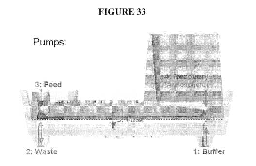
CA 02973388 2017-07-07
WO 2016/112349 PCT/US2016/012744
[0095] FIG. 29 shows an exemplary embodiment of a cartridge.
[0096] FIG. 30 a-d show cell viability after ammonium chloride lysing.
[0097] FIG. 31 shows cell viability after filtration.
[0098] FIG. 32 illustrates an exemplary filter work process. In the exemplary
embodiment of
the process, there are two syringe pumps, one on the right, and the other on
the bottom. Suction on
the bottom one is simultaneous as output on the right one, but faster so that
blood is drawn through
the filter in the differential. Once filtering is done, the suction on the
bottom one is turned off, and
the nucleated cells are pushed back from the filter, which has been flipped
upside down at this time
to dispense the cells directly into a cytometry tube (as in step 6 but with
the syringe replaced with a
receiving cytometry tube).
[0099] FIG. 33 shows an exemplary embodiment of a filtration chamber wherein
the
antechamber and the post-filtration subchamber both have an inlet and an
outlet that allow fluid to
flow trough. In the exemplary embodiment depicted, the fluid in the
antechamber flows antiparallel
to the fluid in the post-filtration subchamber.
[0100] FIG. 34 shows an exemplary embodiment of a multiplex configuration of
eight
filtration chambers that each contains an independent filtration chamber with
fluidic paths
similar to that illustrated in Figure 33.
[0101] FIG. 35 shows an exemplary embodiment of an automated system for
separating
and analyzing a target component of a fluid sample, wherein the sample may be
collected by a
syphon that is placed into the sample, and the sample may pass continuously
through the
antechamber and then be fed directly into an analytical instrument, which in
this schematic is
shown as the flow-cell of a flow cytometer.
[0102] FIG. 36 shows a schematic representation of an exemplary embodiment of
a high-
rinse capacity filtration chamber, wherein the same fluidic path present in
Figure 33 now has a
rinsing reagent (buffer or buffer plus biomarker, or any suitable substance)
introduced from
above and passed through both filters to maximize the interaction between the
sample and the
bottom microfabricated filter.
[0103] FIG. 37 shows an exemplary embodiment of two filtration chambers in
tandem,
wherein the sample may be cleared of debris and small components in the first
filtration
chamber, then the second filtration chamber separates larger cells from
smaller cells among
those remaining. For example, leukocytes may be preferentially directed to the
Recovery 1 port,
and the larger tumor cells may continue to the Recovery 2 port.
19
CA 02973388 2017-07-07
WO 2016/112349 PCT/US2016/012744
[0104] FIG. 38 shows an exemplary embodiment of a filtration chamber with
multiple
recovery ports, wherein the microfabricated filter contains an array of slots
with increasing
width such that each port will output cells of progressively larger size and
the ports may be
spaced as to deliver their output directly into a multi-well screening plate.
Detailed Description of the Invention
Definitions
[0105] Unless defined otherwise, all technical and scientific terms used
herein have the
same meaning as is commonly understood by one of ordinary skill in the art to
which this
invention belongs. All patents, applications, published applications and other
publications
referred to herein are incorporated by reference in their entireties. If a
definition set forth in this
section is contrary to or otherwise inconsistent with a definition set forth
in the patents,
applications, published applications and other publications that are herein
incorporated by
reference, the definition set forth in this section prevails over the
definition that is incorporated
herein by reference.
[0106] As used herein, the singular forms "a", "an", and "the" include plural
references
unless indicated otherwise. For example, "a" dimer includes one or more
dimers.
[0107] A "component" of a sample or "sample component" is any constituent of a
sample,
and can be an ion, molecule, compound, molecular complex, organelle, virus,
cell, aggregate, or
particle of any type, including colloids, aggregates, particulates, crystals,
minerals, etc. A
component of a sample can be soluble or insoluble in the sample media or a
provided sample
buffer or sample solution. A component of a sample can be in gaseous, liquid,
or solid form. A
component of a sample may be a moiety or may not be a moiety.
[0108] A "moiety" or "moiety of interest" is any entity whose isolation,
purification and/or
manipulation is desirable. A moiety can be a solid, including a suspended
solid, or can be in
soluble form. A moiety can be a molecule. Molecules that can be manipulated
include, but are
not limited to, inorganic molecules, including ions and inorganic compounds,
or can be organic
molecules, including amino acids, peptides, proteins, glycoproteins,
lipoproteins,
glycolipoproteins, lipids, fats, sterols, sugars, carbohydrates, nucleic acid
molecules, small
organic molecules, or complex organic molecules. A moiety can also be a
molecular complex,
can be an organelle, can be one or more cells, including prokaryotic and
eukaryotic cells, or can
CA 02973388 2017-07-07
WO 2016/112349 PCT/US2016/012744
be one or more etiological agents, including viruses, parasites, or prions, or
portions thereof. A
moiety can also be a crystal, mineral, colloid, fragment, micelle, droplet,
bubble, or the like, and
can comprise one or more inorganic materials such as polymeric materials,
metals, minerals,
glass, ceramics, and the like. Moieties can also be aggregates of molecules,
complexes, cells,
organelles, viruses, etiological agents, crystals, colloids, or fragments.
Cells can be any cells,
including prokaryotic and eukaryotic cells. Eukaryotic cells can be of any
type. Of particular
interest are cells such as, but not limited to, white blood cells, malignant
cells, stem cells,
progenitor cells, fetal cells, and cells infected with an etiological agent,
and bacterial cells.
Moieties can also be artificial particles such polystyrene microbeads,
microbeads of other
polymer compositions, magnetic microbeads, and carbon microbeads.
[0109] As used herein, "manipulation" refers to moving or processing of the
moieties,
which results in one-, two- or three-dimensional movement of the moiety,
whether within a
single chamber or on a single chip, or between or among multiple chips and/or
chambers.
Moieties that are manipulated by the methods of the present invention can
optionally be coupled
to binding partners, such as microparticles. Non-limiting examples of the
manipulations include
transportation, capture, focusing, enrichment, concentration, aggregation,
trapping, repulsion,
levitation, separation, isolation or linear or other directed motion of the
moieties. For effective
manipulation of moieties coupled to binding partners, the binding partner and
the physical force
used in the method must be compatible. For example, binding partners with
magnetic properties
must be used with magnetic force. Similarly, binding partners with certain
dielectric properties
(e.g., plastic particles, polystyrene microbeads) must be used with
dielectrophoretic force.
[0110] "Binding partner" refers to any substances that both bind to the
moieties with
desired affinity or specificity and are manipulatable with the desired
physical force(s). Non-
limiting examples of the binding partners include cells, cellular organelles,
viruses,
microparticles or an aggregate or complex thereof, or an aggregate or complex
of molecules.
[0111] "Coupled" means bound. For example, a moiety can be coupled to a
microparticle
by specific or nonspecific binding. As disclosed herein, the binding can be
covalent or
noncovalent, reversible or irreversible.
[0112] As used herein, "the moiety to be manipulated is substantially coupled
onto surface
of the binding partner" means that a percentage of the moiety to be
manipulated is coupled onto
surface of the binding partner and can be manipulated by a suitable physical
force via
manipulation of the binding partner. Ordinarily, at least 0.1% of the moiety
to be manipulated is
21
CA 02973388 2017-07-07
WO 2016/112349 PCT/US2016/012744
coupled onto surface of the binding partner. Preferably, at least 1%, 5%, 10%,
20%, 30%, 40%,
50%, 60%, 70%, 80% or 90% of the moiety to be manipulated is coupled onto
surface of the
binding partner.
[0113] As used herein, "the moiety to be manipulated is completely coupled
onto surface of
the binding partner" means that at least 90% of the moiety to be manipulated
is coupled onto
surface of the binding partner. Preferably, at least 91%, 92%, 93%, 94%, 95%,
96%, 97%, 98%,
99% or 100% of the moiety to be manipulated is coupled onto surface of the
binding partner.
[0114] A "specific binding member" is one of two different molecules having an
area on
the surface or in a cavity that specifically binds to and is thereby defined
as complementary with
a particular spatial and chemical organization of the other molecule. A
specific binding member
can be a member of an immunological pair such as antigen-antibody or antibody-
antibody, can
be biotin-avidin, biotin-streptavidin, or biotin-neutravidin, ligand-receptor,
nucleic acid
duplexes, IgG-protein A, DNA-DNA, DNA-RNA, RNA-RNA, and the like.
[0115] An "antibody" is an immunoglobulin molecule, and can be, as a non-
limiting
example, an IgG, an IgM, or other type of immunoglobulin molecule. As used
herein,
"antibody" also refers to a portion of an antibody molecule that retains the
binding specificity of
the antibody from which it is derived (for example, single chain antibodies or
Fab fragments).
[0116] A "nucleic acid molecule" is a polynucleotide. A nucleic acid molecule
can be
DNA, RNA, or a combination of both. A nucleic acid molecule can also include
sugars other
than ribose and deoxyribose incorporated into the backbone, and thus can be
other than DNA or
RNA. A nucleic acid can comprise nucleobases that are naturally occurring or
that do not occur
in nature, such as xanthine, derivatives of nucleobases, such as 2-
aminoadenine, and the like. A
nucleic acid molecule of the present invention can have linkages other than
phosphodiester
linkages. A nucleic acid molecule of the present invention can be a peptide
nucleic acid
molecule, in which nucleobases are linked to a peptide backbone. A nucleic
acid molecule can
be of any length, and can be single-stranded, double-stranded, or triple-
stranded, or any
combination thereof.
[0117] "Homogeneous manipulation" refers to the manipulation of particles in a
mixture
using physical forces, wherein all particles of the mixture have the same
response to the applied
force.
[0118] "Selective manipulation" refers to the manipulation of particles using
physical
forces, in which different particles in a mixture have different responses to
the applied force.
22
CA 02973388 2017-07-07
WO 2016/112349 PCT/US2016/012744
[0119] A "fluid sample" is any fluid from which components are to be separated
or
analyzed. A sample can be from any source, such as an organism, group of
organisms from the
same or different species, from the environment, such as from a body of water
or from the soil,
or from a food source or an industrial source. A sample can be an unprocessed
or a processed
sample. A sample can be a gas, a liquid, or a semi-solid, and can be a
solution or a suspension.
A sample can be an extract, for example a liquid extract of a soil or food
sample, an extract of a
throat or genital swab, or an extract of a fecal sample, or a wash of an
internal area of the body.
[0120] A "blood sample" as used herein can refer to a processed or unprocessed
blood
sample, i.e., it can be a centrifuged, filtered, extracted, or otherwise
treated blood sample,
including a blood sample to which one or more reagents such as, but not
limited to,
anticoagulants or stabilizers have been added. An example of blood sample is a
buffy coat that
is obtained by processing human blood for enriching white blood cells. Another
example of a
blood sample is a blood sample that has been "washed" to remove serum
components by
centrifuging the sample to pellet cells, removing the serum supernatant, and
resuspending the
cells in a solution or buffer. Other blood samples include cord blood samples,
bone marrow
aspirates, internal blood or peripheral blood. A blood sample can be of any
volume, and can be
from any subject such as an animal or human. A preferred subject is a human.
[0121] A "rare cell" is a cell that is either 1) of a cell type that is less
than 1% of the total
nucleated cell population in a fluid sample, or 2) of a cell type that is
present at less than one
million cells per milliliter of fluid sample. A "rare cell of interest" is a
cell whose enrichment is
desirable.
[0122] A "white blood cell" or "WBC" is a leukocyte, or a cell of the
hematopoietic
lineage that is not a reticulocyte or platelet and that can be found in the
blood of an animal or
human. Leukocytes can include nature killer cells ("NK cells") and
lymphocytes, such as B
lymphocytes ("B cells") or T lymphocytes ("T cells"). Leukocytes can also
include phagocytic
cells, such as monocytes, macrophages, and granulocytes, including basophils,
eosinophils and
neutrophils. Leukocytes can also comprise mast cells.
[0123] A "red blood cell" or "RBC" is an erythrocyte. Unless designated a
"nucleated red
blood cell" ("nRBC") or "fetal nucleated red blood cell" or nucleated fetal
red blood cell, as
used herein, "red blood cell" is used to mean a non-nucleated red blood cell.
[0124] "Neoplastic cells" or "tumor cells" refers to abnormal cells that have
uncontrolled
cellular proliferation and can continue to grow after the stimuli that induced
the new growth has
23
CA 02973388 2017-07-07
WO 2016/112349 PCT/US2016/012744
been withdrawn. Neoplastic cells tend to show partial or complete lack of
structural
organization and functional coordination with the normal tissue, and may be
benign or
malignant.
[0125] A "malignant cell" is a cell having the property of locally invasive
and destructive
growth and metastasis. Examples of "malignant cells" include, but are not
limited to, leukemia
cells, lymphoma cells, cancer cells of solid tumors, metastatic solid tumor
cells (e.g., breast
cancer cells, prostate cancer cells, lung cancer cells, colon cancer cells) in
various body fluids
including blood, bone marrow, ascitic fluids, stool, urine, bronchial washes
etc.
[0126] A "cancerous cell" is a cell that exhibits deregulated growth and, in
most cases, has
lost at least one of its differentiated properties, such as, but not limited
to, characteristic
morphology, non-migratory behavior, cell-cell interaction and cell-signaling
behavior, protein
expression and secretion pattern, etc.
[0127] "Cancer" refers to a neoplastic disease that the natural course of
which is fatal.
Cancer cells, unlike benign tumor cells, exhibit the properties of invasion
and metastasis and are
highly anaplastic. Cancer cells include the two broad categories of carcinoma
and sarcoma.
[0128] A "stem cell" is an undifferentiated cell that can give rise, through
one or more cell
division cycles, to at least one differentiated cell type.
[0129] A "progenitor cell" is a committed but undifferentiated cell that can
give rise,
through one or more cell division cycles, to at least one differentiated cell
type. Typically, a
stem cell gives rise to a progenitor cell through one or more cell divisions
in response to a
particular stimulus or set of stimuli, and a progenitor gives rise to one or
more differentiated cell
types in response to a particular stimulus or set of stimuli.
[0130] An "etiological agent" refers to any causal factor, such as bacteria,
fungus,
protozoan, virus, parasite or prion, that can infect a subject. An etiological
agent can cause
symptoms or a disease state in the subject it infects. A human etiological
agent is an etiological
agent that can infect a human subject. Such human etiological agents may be
specific for
humans, such as a specific human etiological agent, or may infect a variety of
species, such as a
promiscuous human etiological agent.
[0131] "Subject" refers to any organism, such as an animal or a human. An
animal can
include any animal, such as a feral animal, a companion animal such as a dog
or cat, an
agricultural animal such as a pig or a cow, or a pleasure animal such as a
horse.
24
CA 02973388 2017-07-07
WO 2016/112349 PCT/US2016/012744
[0132] A "chamber" is a structure that is capable of containing a fluid
sample, in which at
least one processing step can be performed. In some embodiments, a chamber may
have various
dimensions and its volume may vary between 0.01 microliters and 0.5 liter.
[0133] A "filtration chamber" is a chamber through which or in which a fluid
sample can
be filtered.
[0134] A "filter" is a structure that comprises one or more pores or slots of
particular
dimensions (that can be within a particular range), that allow the passage of
some sample
components but not others from one side of the filter to the other, based on
the size, shape,
deformability, binding affinity and/or binding specificity of the components.
A filter can be
made of any suitable material that prevents passage of insoluble components,
such as metal,
ceramics, glass, silicon, plastics, polymers, fibers (such as paper or
fabric), etc.
[0135] A "filtration unit" is a filtration chamber and the associated inlets,
valves, and
conduits that allow sample and solutions to be introduced into the filtration
chamber and sample
components to be removed from the filtration chamber. A filtration unit
optionally also
comprises a loading reservoir.
[0136] A "cartridge" is a structure that comprises at least one chamber that
is part of a
manual or automated system and one or more conduits for the transport of fluid
into or out of at
least one chamber. A cartridge may or may not comprise one or more chips.
[0137] An "automated system for separating a target component from a fluid
sample" or an
"automated system" is a device that comprises at least one filtration chamber,
automated means
for directing fluid flow through the filtration chamber, and at least one
power source for
providing fluid flow and, optionally, providing a signal source for the
generation of forces on
active chips. An automated system of the present invention can also optionally
include one or
more active chips, separation chambers, separation columns, or permanent
magnets.
[0138] A "port" is an opening in the housing of a chamber through which a
fluid sample
can enter or exit the chamber. A port can be of any dimensions, but preferably
is of a shape and
size that allows a sample to be dispensed into a chamber by pumping a fluid
through a conduit,
or by means of a pipette, syringe, or other means of dispensing or
transporting a sample.
[0139] An "inlet" is a point of entrance for sample, solutions, buffers, or
reagents into a
fluidic chamber. An inlet can be a port of a chamber, or can be an opening in
a conduit that
leads, directly or indirectly, to a chamber of an automated system.
CA 02973388 2017-07-07
WO 2016/112349 PCT/US2016/012744
[0140] An "outlet" is the opening at which sample, sample components, or
reagents exit a
fluidic chamber. The sample components and reagents that leave a chamber can
be waste, i.e.,
sample components that are not to be used further, or can be sample components
or reagents to
be recovered, such as, for example, reusable reagents or target cells to be
further analyzed or
manipulated. An outlet can be a port of a chamber, but preferably is an
opening in a conduit that,
directly or indirectly, leads from a chamber of an automated system.
[0141] A "conduit" is a means for fluid to be transported from a container to
a chamber of
the present invention. Preferably a conduit directly or indirectly engages a
port in the housing of
a chamber. A conduit can comprise any material that permits the passage of a
fluid through it.
Conduits can comprise tubing, such as, for example, rubber, Teflon, or tygon
tubing. Conduits
can also be molded out of a polymer or plastic, or drilled, etched, or
machined into a metal, glass
or ceramic substrate. Conduits can thus be integral to structures such as, for
example, a cartridge
of the present invention. A conduit can be of any dimensions, but preferably
ranges from 10
microns to 5 millimeters in internal diameter. A conduit is preferably
enclosed (other than fluid
entry and exit points), or can be open at its upper surface, as a canal-type
conduit.
[0142] A "chip" is a solid substrate on which one or more processes such as
physical,
chemical, biochemical, biological or biophysical processes can be carried out,
or a solid
substrate that comprises or supports one or more applied force-generating
elements for carrying
out one or more physical, chemical, biochemical, biological, or biophysical
processes. Such
processes can be assays, including biochemical, cellular, and chemical assays;
separations,
including separations mediated by electrical, magnetic, physical, and chemical
(including
biochemical) forces or interactions; chemical reactions, enzymatic reactions,
and binding
interactions, including captures. The micro structures or micro-scale
structures such as,
channels and wells, bricks, dams, filters, electrode elements, electromagnetic
elements, or
acoustic elements, may be incorporated into or fabricated on the substrate for
facilitating
physical, biophysical, biological, biochemical, chemical reactions or
processes on the chip. The
chip may be thin in one dimension and may have various shapes in other
dimensions, for
example, a rectangle, a circle, an ellipse, or other irregular shapes. The
size of the major surface
of chips of the present invention can vary considerably, e.g., from about 1
mm2 to about 0.25 m2.
Preferably, the size of the chips is from about 4 mm2 to about 25 cm2 with a
characteristic
dimension from about 1 mm to about 5 cm. The chip surfaces may be flat, or not
flat. The chips
26
CA 02973388 2017-07-07
WO 2016/112349 PCT/US2016/012744
with non-flat surfaces may include channels or wells fabricated on the
surfaces. A chip can have
one or more openings, such as pores or slots.
[0143] An "active chip" is a chip that comprises micro-scale structures that
are built into or
onto a chip that when energized by an external power source can generate at
least one physical
force that can perform a processing step or task or an analysis step or task,
such as, but not
limited to, mixing, translocation, focusing, separation, concentration,
capture, isolation, or
enrichment. An active chip uses applied physical forces to promote, enhance,
or facilitate
desired biochemical reactions or processing steps or tasks or analysis steps
or tasks. On an
active chip, "applied physical forces" are physical forces that, when energy
is provided by a
power source that is external to an active chip, are generated by micro-scale
structures built into
or onto a chip.
[0144] "Micro-scale structures" are structures integral to or attached on a
chip, wafer, or
chamber that have characteristic dimensions of scale for use in microfluidic
applications ranging
from about 0.1 micron to about 20 mm. Example of micro-scale structures that
can be on chips
of the present invention are wells, channels, dams, bricks, filters,
scaffolds, electrodes,
electromagnetic units, acoustic elements, or microfabricated pumps or valves.
A variety of
micro-scale structures are disclosed in United States Patent Application
Number 09/679,024,
having attorney docket number 471842000400, entitled "Apparatuses Containing
Multiple
Active Force Generating Elements and Uses Thereof' filed October 4, 2000,
herein incorporated
by reference in its entirety. Micro-scale structures that can, when energy,
such as an electrical
signal, is applied, generate physical forces useful in the present invention,
can be referred to as
"physical force-generating elements" "physical force elements", "active force
elements", or
"active elements".
[0145] A variety of micro-scale structures are disclosed in United States
Patent Application
Number 09/679,024, having attorney docket number 471842000400, entitled
"Apparatuses
Containing Multiple Active Force Generating Elements and Uses Thereof' filed
October 4,
2000, herein incorporated by reference in its entirety. Micro-scale structures
that can, when
energy, such as an electrical signal, is applied, generate physical forces
useful in the present
invention, can be referred to as "physical force-generating elements",
"physical force elements",
"active force elements", or "active elements".
[0146] A "multiple force chip" or "multiforce chip" is a chip that generates
physical force
fields and that has at least two different types of built-in structures each
of which is, in
27
CA 02973388 2017-07-07
WO 2016/112349 PCT/US2016/012744
combination with an external power source, capable of generating one type of
physical field. A
full description of the multiple force chip is provided in United States
Application Number
09/679,024 having attorney docket number 471842000400, entitled "Apparatuses
Containing
Multiple Active Force Generating Elements and Uses Thereof' filed October 4,
2000, herein
incorporated by reference in its entirety.
[0147] "Acoustic forces" are the forces exerted, directly or indirectly on
moieties (e.g.,
particles and/or molecules) by an acoustic wave field. Acoustic forces can be
used for
manipulating (e.g., trapping, moving, directing, handling) particles in fluid.
Acoustic waves,
both standing acoustic wave and traveling acoustic wave, can exert forces
directly on moieties
and such forces are called "acoustic radiation forces". Acoustic wave may also
exert forces on
the fluid medium in which the moieties are placed, or suspended, or dissolved
and result in so-
called acoustic streaming. The acoustic streaming, in turn, will exert forces
on the moieties
placed, suspended or dissolved in such a fluid medium. In this case, the
acoustic wave fields
can exert forces on moieties in directly.
[0148] "Acoustic elements" are structures that can generate an acoustic wave
field in
response to a power signal. Preferred acoustic elements are piezoelectric
transducers that can
generate vibrational (mechanical) energy in response to applied AC voltages.
The vibrational
energy can be transferred to a fluid that is in proximity to the transducers,
causing an acoustic
force to be exerted on particles (such as, for example, cells) in the fluid. A
description of
acoustic forces and acoustic elements can be found in U.S. Patent Application
09/636,104, filed
Aug. 10, 2000, incorporated by reference in its entirety.
[0149] "Piezoelectic transducers" are structures capable of generating an
acoustic field in
response to an electrical signal. Non-limiting examples of the piezoelectric
transducers are
ceramic disks (e.g. PZT, Lead Zirconium Titinate) covered on both surfaces
with metal film
electrodes, piezoelectric thin films (e.g. zinc-oxide).
[0150] "Mixing", as used herein, means the use of physical forces to cause
movement in a
sample, solution, or mixture, such that components of the sample, solution, or
mixture become
interspersed. Preferred methods of mixing for use in the present invention
include use of
acoustic forces.
[0151] "Processing" refers to the preparation of a sample for analysis, and
can comprise
one or multiple steps or tasks. Generally a processing task serves to separate
components of a
28
CA 02973388 2017-07-07
WO 2016/112349 PCT/US2016/012744
sample, concentrate components of a sample, at least partially purify
components of a sample, or
structurally alter components of a sample (for example, by lysis or
denaturation).
[0152] As used herein, "isolating" means separating a desirable sample
component from
other non-desirable components of a sample, such that preferably, at least
15%, more preferably
at least 30%, even more preferably at least 50%, and further preferably, at
least 80% of the
desirable sample components present in the original sample are retained, and
preferably at least
50%, more preferably at least 80%, even more preferably, at least 95%, and yet
more preferably,
at least 99%, of at least one nondesirable component of the original component
is removed, from
the final preparation.
[0153] "Enrich" means increase the concentration of a sample component of a
sample
relative to other sample components (which can be the result of reducing the
concentration of
other sample components), or increase the concentration of a sample component.
For example,
as used herein, "enriching" nucleated fetal cells from a blood sample means
increasing the
proportion of nucleated fetal cells to all cells in the blood sample,
enriching cancer cells of a
blood sample can mean increasing the concentration of cancer cells in the
sample (for example,
by reducing the sample volume) or reducing the concentration of other cellular
components of
the blood sample, and "enriching" cancer cells in a urine sample can mean
increasing their
concentration in the sample.
[0154] "Separation" is a process in which one or more components of a sample
are spatially
separated from one or more other components of a sample. A separation can be
performed such
that one or more sample components of interest is translocated to or retained
in one or more
areas of a separation apparatus and at least some of the remaining components
are translocated
away from the area or areas where the one or more sample components of
interest are
translocated to and/or retained in, or in which one or more sample components
is retained in one
or more areas and at least some or the remaining components are removed from
the area or
areas. Alternatively, one or more components of a sample can be translocated
to and/or retained
in one or more areas and one or more sample components can be removed from the
area or
areas. It is also possible to cause one or more sample components to be
translocated to one or
more areas and one or more sample components of interest or one or more
components of a
sample to be translocated to one or more other areas. Separations can be
achieved through, for
example, filtration, or the use of physical, chemical, electrical, or magnetic
forces. Nonlimiting
29
CA 02973388 2017-07-07
WO 2016/112349 PCT/US2016/012744
examples of forces that can be used in separations are gravity, mass flow,
dielectrophoretic
forces, traveling-wave dielectrophoretic forces, and electromagnetic forces.
[0155] "Separating a sample component from a (fluid) sample" means separating
a sample
component from other components of the original sample, or from components of
the sample
that are remaining after one or more processing steps. "Removing a sample
component from a
(fluid) sample" means removing a sample component from other components of the
original
sample, or from components of the sample that are remaining after one or more
processing steps.
[0156] "Capture" is a type of separation in which one or more moieties or
sample
components is retained in or on one or more areas of a surface, chamber, chip,
tube, or any
vessel that contains a sample, where the remainder of the sample can be
removed from that area.
[0157] An "assay" is a test performed on a sample or a component of a sample.
An assay
can test for the presence of a component, the amount or concentration of a
component, the
composition of a component, the activity of a component, etc. Assays that can
be performed in
conjunction with the compositions and methods of the present invention
include, but are not
limited to, immunocytochemical assays, interphase FISH (fluorescence in situ
hybridization),
karyotyping, immunological assays, biochemical assays, binding assays,
cellular assays, genetic
assays, gene expression assays and protein expression assays.
[0158] A "binding assay" is an assay that tests for the presence or
concentration of an entity
by detecting binding of the entity to a specific binding member, or that tests
the ability of an
entity to bind another entity, or tests the binding affinity of one entity for
another entity. An
entity can be an organic or inorganic molecule, a molecular complex that
comprises, organic,
inorganic, or a combination of organic and inorganic compounds, an organelle,
a virus, or a cell.
Binding assays can use detectable labels or signal generating systems that
give rise to detectable
signals in the presence of the bound entity. Standard binding assays include
those that rely on
nucleic acid hybridization to detect specific nucleic acid sequences, those
that rely on antibody
binding to entities, and those that rely on ligands binding to receptors.
[0159] A "biochemical assay" is an assay that tests for the presence,
concentration, or
activity of one or more components of a sample.
[0160] A "cellular assay" is an assay that tests for a cellular process, such
as, but not
limited to, a metabolic activity, a catabolic activity, an ion channel
activity, an intracellular
signaling activity, a receptor-linked signaling activity, a transcriptional
activity, a translational
activity, or a secretory activity.
CA 02973388 2017-07-07
WO 2016/112349 PCT/US2016/012744
[0161] A "genetic assay" is an assay that tests for the presence or sequence
of a genetic
element, where a genetic element can be any segment of a DNA or RNA molecule,
including,
but not limited to, a gene, a repetitive element, a transposable element, a
regulatory element, a
telomere, a centromere, or DNA or RNA of unknown function. As nonlimiting
examples,
genetic assays can be gene expression assays, PCR assays, karyotyping, or
FISH. Genetic assays
can use nucleic acid hybridization techniques, can comprise nucleic acid
sequencing reactions,
or can use one or more enzymes such as polymerases, as, for example a genetic
assay based on
PCR. A genetic assay can use one or more detectable labels, such as, but not
limited to,
fluorochromes, radioisotopes, or signal generating systems.
[0162] "Immunostaining" refers to staining of a specific antigen or structure
by any method
in which the stain (or stain-generating system) is complexed with a specific
antibody.
[0163] "Polymerase chain reaction" or "PCR" refers to method for amplifying
specific
sequences of nucleotides (amplicon). PCR depends on the ability of a nucleic
acid polymerase,
preferably a thermostable one, to extend a primer on a template containing the
amplicon. RT-
PCR is a PCR based on a template (cDNA) generated from reverse transcription
from mRNA
prepared from a sample. Quantitative Reverse Transcription PCR (qRT-PCR) or
the Real-Time
RT-PCR is a RT-PCR in which the RT-PCR products for each sample in every cycle
are
quantified.
[0164] "FISH" or "fluorescence in situ hybridization" is an assay wherein a
genetic marker
can be localized to a chromosome by hybridization. Typically, to perform FISH,
a nucleic acid
probe that is fluorescently labeled is hybridized to interphase chromosomes
that are prepared on
a slide. The presence and location of a hybridizing probe can be visualized by
fluorescence
microscopy. The probe can also include an enzyme and be used in conjunction
with a
fluorescent enzyme substrate.
[0165] "Karyotyping" refers to the analysis of chromosomes that includes the
presence and
number of chromosomes of each type (for example, each of the 24 chromosomes of
the human
haplotype (chromosomes 1-22, X, and Y)), and the presence of morphological
abnormalities in
the chromosomes, such as, for example, translocations or deletions.
Karyotyping typically
involves performing a chromosome spread of a cell in metaphase. The
chromosomes can then be
visualized using, for example, but not limited to, stains or genetic probes to
distinguish the
specific chromosomes.
31
CA 02973388 2017-07-07
WO 2016/112349 PCT/US2016/012744
[0166] A "gene expression assay" (or "gene expression profiling assay") is an
assay that
tests for the presence or quantity of one or more gene expression products,
i.e. messenger RNAs.
The one or more types of mRNAs can be assayed simultaneously on cells of the
interest from a
sample. For different applications, the number and/or the types of mRNA
molecules to be
assayed in the gene expression assays may be different.
[0167] A "protein expression assay" (or "protein expression profiling assay")
is an assay
that tests for the presence or quantity of one or more proteins. One or more
types of protein can
be assayed simultaneously on the cells of the interest from a sample. For
different applications,
the number and/or the types of protein molecules to be assayed in the protein
expression assays
may be different.
[0168] "Histological examination" refers to the examination of cells using
histochemical or
stains or specific binding members (generally coupled to detectable labels)
that can determine
the type of cell, the expression of particular markers by the cell, or can
reveal structural features
of the cell (such as the nucleus, cytoskeleton, etc.) or the state or function
of a cell. In general,
cells can be prepared on slides and "stained" using dyes or specific binding
members directly or
indirectly bound to detectable labels, for histological examination. Examples
of dyes that can be
used in histological examination are nuclear stains, such as Hoechst stains,
or cell viability
stains, such as Trypan blue, or cellular structure stains such as Wright or
Giemsa, enzyme
activity benzidine for HRP to form visible precipitate. Examples of specific
binding members
that can be used in histological examination of fetal red blood cells are
antibodies that
specifically recognize fetal or embryonic hemoglobin.
[0169] An "electrode" is a structure of highly electrically conductive
material. A highly
conductive material is a material with a conductivity greater than that of
surrounding structures
or materials. Suitable highly electrically conductive materials include
metals, such as gold,
chromium, platinum, aluminum, and the like, and can also include nonmetals,
such as carbon
and conductive polymers. An electrode can be any shape, such as rectangular,
circular,
castellated, etc. Electrodes can also comprise doped semi-conductors, where a
semi-conducting
material is mixed with small amounts of other "impurity" materials. For
example, phosphorous-
doped silicon may be used as conductive materials for forming electrodes.
[0170] A "well" is a structure in a chip, with a lower surface surrounded on
at least two
sides by one or more walls that extend from the lower surface of the well or
channel. The walls
can extend upward from the lower surface of a well or channel at any angle or
in any way. The
32
CA 02973388 2017-07-07
WO 2016/112349 PCT/US2016/012744
walls can be of an irregular conformation, that is, they may extend upward in
a sigmoidal or
otherwise curved or multi-angled fashion. The lower surface of the well or
channel can be at the
same level as the upper surface of a chip or higher than the upper surface of
a chip, or lower than
the upper surface of a chip, such that the well is a depression in the surface
of a chip. The sides
or walls of a well or channel can comprise materials other than those that
make up the lower
surface of a chip.
[0171] A "channel" is a structure in a chip with a lower surface and at least
two walls that
extend upward from the lower surface of the channel, and in which the length
of two opposite
walls is greater than the distance between the two opposite walls. A channel
therefore allows for
flow of a fluid along its internal length. A channel can be covered (a
"tunnel") or open.
[0172] A "pore" is an opening in a surface, such as a filter of the present
invention, that
provides fluid communication between one side of the surface and the other. A
pore can be of
any size and of any shape, but preferably a pore is of a size and shape that
restricts passage of at
least one insoluble sample component from one side of a filter to the other
side of a filter based
on the size, shape, deformability, binding affinity and/or binding specificity
(or lack thereof), of
the sample component.
[0173] A "slot" is an opening in a surface, such as a filter of the present
invention. The slot
length is longer than its width (slot length and slot width refer to the slots
dimensions in the
plane or the surface of the filter into which the sample components will go
through, and slot
depth refers to the thickness of the filter). The term "slot" therefore
describes the shape of a
pore, which will in some cases be approximately rectangular, ellipsoid, or
that of a quadrilateral
or parallelogram.
[0174] "Bricks" are structures that can be built into or onto a surface that
can restrict the
passage of sample components between bricks. The design and use of one type of
bricks (called
"obstacles") on a chip is described in U.S. Patent No. 5,837,115 issued Nov.
17, 1998 to Austin
et al., herein incorporated by reference in its entirety.
[0175] A "dam" is a structure that can be built onto the lower surface of a
chamber that
extends upward toward the upper surface of a chamber leaving a space of
defined width between
the top of the dam and the top of the chamber. Preferably, the width of the
space between the top
of the dam and the upper wall of the chamber is such that fluid sample can
pass through the
space, but at least one sample component is unable to pass through the space
based on its size,
shape, or deformability (or lack thereof). The design and use of one type of
dam structure on a
33
CA 02973388 2017-07-07
WO 2016/112349 PCT/US2016/012744
chip is described in U.S. Patent No. 5,928,880 issued Jul. 27, 1999 to Wilding
et al., herein
incorporated by reference in its entirety.
[0176] "Continuous flow" means that fluid is pumped or injected into a chamber
of the
present invention continuously during the separation process. This allows for
components of a
sample that are not selectively retained in a chamber to be flushed out of the
chamber during the
separation process.
[0177] "Binding partner" refers to any substances that both bind to the
moieties with
desired affinity or specificity and are manipulatable with the desired
physical force(s). Non-
limiting examples of the binding partners include microparticles.
[0178] A "microparticle" is a structure of any shape and of any composition
that is
manipulatable by desired physical force(s). The microparticles used in the
methods could have a
dimension from about 0.01 micron to about ten centimeters. Preferably, the
microparticles used
in the methods have a dimension from about 0.1 micron to about several hundred
microns. Such
particles or microparticles can be comprised of any suitable material, such as
glass or ceramics,
and/or one or more polymers, such as, for example, nylon,
polytetrafluoroethylene
(TEFLONTm), polystyrene, polyacrylamide, sepaharose, agarose, cellulose,
cellulose
derivatives, or dextran, and/or can comprise metals. Examples of
microparticles include, but are
not limited to, magnetic beads, magnetic particles, plastic particles, ceramic
particles, carbon
particles, polystyrene microbeads, glass beads, hollow glass spheres, metal
particles, particles of
complex compositions, microfabricated free-standing microstructures, etc. The
examples of
microfabricated free-standing microstructures may include those described in
"Design of
asynchronous dielectric micromotors" by Hagedorn et al., in Journal of
Electrostatics, Volume:
33, Pages 159-185 (1994). Particles of complex compositions refer to the
particles that
comprise or consists of multiple compositional elements, for example, a
metallic sphere covered
with a thin layer of non-conducting polymer film.
[0179] "A preparation of microparticles" is a composition that comprises
microparticles of
one or more types and can optionally include at least one other compound,
molecule, structure,
solution, reagent, particle, or chemical entity. For example, a preparation of
microparticles can
be a suspension of microparticles in a buffer, and can optionally include
specific binding
members, enzymes, inert particles, surfactants, ligands, detergents, etc.
[0180] As used herein, the term "substantially anti-parallel" and
"substantially opposite"
are understood to mean "approximately anti-parallel" and "approximately
opposite",
34
CA 02973388 2017-07-07
WO 2016/112349 PCT/US2016/012744
respectively, such as within about 30 , preferably within about 20 , more
preferably within
about 10 , and most preferably within about 5 or less of being perfectly anti-
parallel or
opposite.
[0181] As used herein, the term "engaged" refers to any mode of mechanical or
physical
attachment, interlocking, mating, binding, or coupling, such that members that
are said to be
"engaged" do not come apart or detach from one another without some positive
effort,
application of energy, or the like.
[0182] It is understood that aspects and embodiments of the invention
described herein
include "consisting" and/or "consisting essentially of' aspects and
embodiments.
[0183] Throughout this disclosure, various aspects of this invention are
presented in a range
format. It should be understood that the description in range format is merely
for convenience
and brevity and should not be construed as an inflexible limitation on the
scope of the invention.
Accordingly, the description of a range should be considered to have
specifically disclosed all
the possible sub-ranges as well as individual numerical values within that
range. For example,
description of a range such as from 1 to 6 should be considered to have
specifically disclosed
sub-ranges such as from 1 to 3, from 1 to 4, from 1 to 5, from 2 to 4, from 2
to 6, from 3 to 6
etc., as well as individual numbers within that range, for example, 1, 2, 3,
4, 5, and 6. This
applies regardless of the breadth of the range.
[0184] Other technical terms used herein have their ordinary meaning in the
art that they
are used, as exemplified by a variety of technical dictionaries.
Introduction
[0185] The present invention recognizes that analysis of complex fluids, such
as biological
fluid samples, can be confounded by many sample components that can interfere
with the
analysis. Sample analysis can be even more problematic when the target of the
analysis is a rare
cell type: for example, when the target cells are fetal cells present in
maternal blood or
malignant cells present in the blood or urine of a patient. In processing such
samples, it is often
necessary to both "debulk" the sample, by reducing the volume to a manageable
level, and to
enrich the population of rare cells that are the target of analysis (see,
e.g., U.S. Patent Nos.
6,949,355 and 7,166,443; U.S. Patent Publication Nos. 2006/0252054,
2007/0202536,
2008/0057505 and 2008/0206757). Procedures for the processing of fluid samples
are often time
CA 02973388 2017-07-07
WO 2016/112349 PCT/US2016/012744
consuming and inefficient. In some aspects, the present invention provides
efficient methods and
automated systems for the separation of a target component from fluid samples.
[0186] As a non-limiting introduction to the breadth of the present invention,
the present
invention includes several general and useful aspects, including:
1) a filtration chamber comprising a microfabricated filter enclosed in a
housing, wherein
the filtration chamber comprises an antechamber and a post-filtration
subchamber, and the fluid
flow path in the antechamber is substantially opposite to the fluid flow path
in the post-filtration
subchamber;
2) a filtration chamber comprising a microfabricated filter enclosed in a
housing, wherein
the surface of said filter and/or the inner surface of said housing are
modified by vapor
deposition, sublimation, vapor-phase surface reaction, or particle sputtering
to produce a
uniform coating;
3) a filtration chamber comprising a microfabricated filter enclosed in a
housing, wherein
the surface of said filter and/or the inner surface of said housing are
modified by a metal nitride,
a metal halide, a Parylene or derivative thereof, a polytetrafluoroethylene
(PTFE), a Teflon-AF
or a perfluorocarbon;
4) a cartridge comprising a filtration chamber disclosed herein;
5) an automated filtration unit for separating a target component in a fluid
sample,
comprising a filtration chamber disclosed herein;
6) an automated system for separating and analyzing a target component in a
fluid
sample, comprising an automated filtration unit disclosed herein and an
analysis apparatus
connected to the filtration unit;
7) a method for separating a target component in a fluid sample, comprising:
a)
dispensing a fluid sample into the filtration chamber disclosed herein; and b)
providing a fluid
flow of the fluid sample through the filtration chamber, wherein the target
component of the
fluid sample is retained by or passes through the filter;
8) a method of separating a target component in a fluid sample using the
automated
filtration unit disclosed herein, comprising: a) dispensing the fluid sample
into the filtration
chamber; and b) providing a fluid flow of the fluid sample through the
filtration chamber,
wherein the target component of the fluid sample is retained by or flows
through the filter; and
9) a method of enriching and analyzing a component in a fluid sample using the
automated system disclosed herein, comprising: a) dispensing the fluid sample
into the filtration
36
CA 02973388 2017-07-07
WO 2016/112349 PCT/US2016/012744
chamber; b) providing a fluid flow of the fluid sample through the antechamber
of the filtration
chamber and a fluid flow of a solution through the post-filtration subchamber
of the filtration
chamber, wherein the target component of the fluid sample is retained in the
antechamber and
non-target components flow through the filter into the post-filtration
subchamber; c) labeling the
target component; and d) analyzing the labeled target component using the
analysis apparatus.
[0187] These aspects of the invention, as well as others described herein, can
be achieved
by using the methods, articles of manufacture and compositions of matter
described herein. To
gain a full appreciation of the scope of the present invention, it will be
further recognized that
various aspects of the present invention can be combined to make desirable
embodiments of the
invention.
I Filtration Chamber
[0188] In one aspect, the present invention provides a filtration chamber
comprising a
microfabricated filter enclosed in a housing. In embodiments in which a
filtration chamber of
the present invention comprises one or more microfabricated filters that are
internal to the
chamber, the filter or filters can divide the chamber into subchambers. Where
a filtration
chamber comprises a single internal microfabricated filter, for example, the
filtration chamber
can comprise a prefiltration "antechamber", or where appropriate, "upper
subchamber" and a
"post-filtration subchamber", or, where appropriate, "lower subchamber". In
other cases, a
microfabricated filter can form a wall of a filtration chamber, and during
filtration, filterable
sample components exit the chamber via the filter.
[0189] In some embodiments of the present invention, a filtration chamber of
the present
invention has at least one port that allows for the introduction of a sample
into the chamber, and
conduits can transport sample to and from a filtration chamber of the present
invention. When
fluid flow commences, sample components that flow through one or more filters
can flow into
one or more areas of the chamber and then out of the chamber through conduits,
and, preferably
but optionally, from the conduits into a vessel, such as a waste vessel. The
filtration chamber can
also optionally have one or more additional ports for the additions of one or
more reagents,
solutions, or buffers. Throughout this description, it is understood that the
inflow ports or
outflow ports may be used with flow in the direction opposite to their named
function.
37
CA 02973388 2017-07-07
WO 2016/112349 PCT/US2016/012744
[0190] In some embodiments, the filtration chamber may comprise an additional
filter, or
where appropriate, a "suprafilter". In some embodiments, the suprafilter,
between the
antechamber and the suprachamber, may be any filter sufficiently rigid to
maintain its flatness in
slow flow conditions and be produced by any method that results in holes or
slots with openings
smaller than 5 microns. The suprafilter may further divide the antechamber or
post-filtration
subchamber. In some embodiments, the filtration antechamber may comprise an
inflow port, an
outflow port, and an additional inflow port, further where the additional
inflow port is separated
from the antechamber by another microfabricated filter thereby creating a
suprachamber.
[0191] A filtration chamber of the present invention can comprise one or more
fluid-
impermeable materials, such as but not limited to, metals, polymers, plastics,
ceramics, glass,
silicon, or silicon dioxide. Preferably, a filtration chamber of the present
invention has a
volumetric capacity of from about 0.01 milliliters to about ten liters, more
preferably from about
0.2 milliliters to about two liters. In some preferred embodiments of the
present invention, a
filtration chamber can have a volume of from about 1 milliliter to about 80
milliliters.
[0192] A filtration chamber of the present invention can comprise or engage
any number of
filters. In one preferred embodiment of the present invention, a filtration
chamber comprises one
filter (see, for example Figure 5 and Figure 14). In another preferred
embodiment of the present
invention, a filtration chamber comprises more than one filter, such as the
chamber exemplified
in Figure 6 and Figure 7. Various filter chamber configurations are possible.
For example, it is
within the scope of the present invention to have a filtration chamber in
which one or more walls
of the filter chamber comprises a microfabricated filter. It is also within
the scope of the present
invention to have a filtration chamber in which a filter chamber engages one
or more filters. In
this case, the filters can be permanently engaged with the chamber, or can be
removable (for
example, they can be inserted into slots or tracks provided on the chamber). A
filter can be
provided as a wall of a chamber, or internal to a chamber, and filters can
optionally be provided
in tandem for sequential filtering. Where filters are inserted into a chamber,
they are inserted to
form a tight seal with the walls of a chamber, such that during the filtration
operation, fluid flow
through the chamber (from one side of a filter to the other) must be through
the pores of the
filter.
[0193] In a preferred embodiment of the present invention, a filtration
chamber of, for
example, approximately one centimeter by one centimeter by 0.2 to ten
centimeters in
dimensions can have one or more filters comprising from four to 1,000,000
slots, preferably
38
CA 02973388 2017-07-07
WO 2016/112349 PCT/US2016/012744
from 100 to 250,000 slots. In this preferred embodiment, the slots are
preferably of rectangular
shape, with a slot length of from about 0.1 to about 1,000 microns, and slot
width is preferably
from about 0.1 to about 100 microns, depending on the application.
[0194] Preferably, slots can allow for the passage of mature red blood cells
(lacking nuclei)
through the channels and thus out of the chamber, while not or minimally
allowing cells having
a greater diameter or shape (for example but not limited to, nucleated cells
such as white blood
cells and nucleated red blood cells) to exit the chamber. A filtration chamber
that can allow the
removal of red blood cells by fluid flow through the chamber, while retaining
other cells of a
blood sample, is illustrated in Figure 7, Figure 14, and Figure 16. For
example, for removing
matured red blood cells from nucleated RBCs and white blood cells, slot widths
between 2.5 and
6.0 microns, more preferably between 2.2 and 4.0 microns, could be used. Slot
length could
vary between, for example, 20 and 200 microns. Slot depth (i.e., filter
membrane thickness) can
vary between 40 and 100 microns. The slot width between 2.0 and 4.0 microns
would allow the
double-discoid-shaped RBCs to go through the slots while primarily retaining
the nucleated
RBCs and WBCs with diameters or shapes larger than 7 micron.
Anti-Parallel Flow
[0195] In some embodiments, a filtration chamber of the present invention may
be
configured to allow parallel or anti-parallel fluid flow in the antechamber
and the post-filtration
subchamber. The antechamber may have two ports, an inflow port and an out flow
port. The
post-filtration subchamber may have two ports, an inflow port and an outflow
port. The ports
may be arranged in such a way that fluid flows in the antechamber and in the
post-filtration
subchamber are substantially opposite, or anti-parallel, of each other. The
inflow port of the
antechamber may be used to dispense a fluid sample, such as a blood sample, a
cell suspension,
or the like, into the filtration chamber.
[0196] In some embodiments, the device has a single antechamber with two ports
for
inflow and outflow, one on either side of the one or more filters, such that
blood samples can
flow through the antechamber. For example, blood samples can be pumped through
the
antechamber to fill the chamber. In preferred embodiments in which one opening
comprises a
reservoir at its end, particles such as cells and compounds can optionally be
added via the
reservoir. In the alternative, either particles, compounds, or both can be
added to the
antechamber at an opening that is not connected to a reservoir. In some
embodiments, the
39
CA 02973388 2017-07-07
WO 2016/112349 PCT/US2016/012744
antechamber may comprise more than one inflow and/or outflow ports. For
example, an
additional inflow port may be used for provide inflow of a solution for
rinsing, or provide a
fluidic force to push components of a fluid sample across the filter. In
embodiments wherein a
suprafilter is included to divide the antechamber into a suprachamber and an
antechamber, the
additional inflow port may provide fluid flow to the suprafilter.
[0197] In some preferred embodiments, the post-filtration subchamber is also a
single flow-
through channel, with an opening at one end for the introduction of solutions,
and an opening at
the other end for outflow of solutions. In some embodiments, the post-
filtration subchamber
may comprise more than one inflow and/or outflow ports. For example, multiple
outflow ports
in the post-filtration subchamber may be used to collect different filtration
components based on
the size, shape, deformability, binding affinity and/or binding specificity of
the components.
[0198] In some embodiments, the fluid flow in the antechamber and the post-
filtration
subchamber may be such that a negative pressure may be created to draw
components or cells
through the filter. In some embodiments, the outflow from the bottom chamber
is greater than
the inflow into the bottom chamber such that a portion of the fluid sample
traversing the
antechamber may be drawn into the post-filtration subchamber such that the red
blood cells and
platelets will be separated from the white blood cells and other nucleated
cells that will be
retained in the antechamber by the filter. In some embodiments, the outflow
fluid may contain
fewer cells than the inflow fluid.
[0199] In some embodiments, the fluid flow of the antechamber and post-
filtration
subchamber may be configured so that they have different flow rates. It is
contemplated that the
difference in the fluid flow in the antechamber and post-filtration subchamber
may create a fluid
force across the filter between the antechamber and post-filtration
subchamber. The flow rate of
the fluid in the antechamber and post-filtration subchamber may be controlled
by a pressure
control unit, such as a pump, at the inflow and/or outflow ports. In some
embodiments, the
pressure control unit may be adjusted by an automatic control system, such as
a computer
running an algorithm.
[0200] The filtration chamber may include one or more surface contours to
affect the flow
of a sample, a solution such as wash or elution solution or both. For example
contours may
deflect, disperse or direct a sample to assist in the spreading of the sample
along the filter.
Alternatively, contours may deflect, disperse or direct a wash solution such
that the wash
solution washes the chamber or filter with greater efficiency. Such surface
contours may be in
CA 02973388 2017-07-07
WO 2016/112349 PCT/US2016/012744
any appropriate configuration. The contours may include surfaces that project
generally toward
the chip or may project generally away from the chip. They may generally
encircle the filter.
Contours may include but are not limited to projections, recessed portions,
slots, deflection
structures such as ball-like portions, bubbles (formed from e.g. air,
detergent, or polymers), and
the like. Contours such as two or more slots may be configured generally
parallel to one another
yet generally angled when viewing the chamber upright to direct flow in a
generally spiraled
path.
[0201] In some embodiments, the outflow port of the antechamber may be
connected to a
collection chamber, wherein the target components of the fluid sample, such as
nucleated cells
from a blood sample, or cancerous cells from a cell suspension, may be
collected after unwanted
components have been separated by filtration.
[0202] In some embodiments, the filtration chamber of the present invention
may be
formed by two housing parts, for example, a top housing part and a bottom
housing part, which
may reversibly engage to form the filtration chamber that encloses the filter.
The housing parts
may be bound together using any suitable methods, such as but not limited to,
laser bonding,
adhesive material, or the like. The bottom housing part can be in the form of
a tray or tank, and
preferably has at least one inlet and at least one outlet for allowing buffer
to flow through the
chamber.
Surface Treatment or Modification
[0203] In some embodiments, the present invention provides treatment or
modifications to
the surface of a microfabricated filter and/or the inner surface of a housing
that encloses the
microfabricated filter to improve its filtering efficiency. In some
embodiments, the surface
treatment produces a uniform coating of the filter and the housing. In some
embodiments, one
or both surfaces of the filter is treated or coated or modified to increase
its filtering efficiency.
The surface modifications may facilitate the filtration of components of the
fluid sample across
the filter, or reduce blocking of the slots on the filter by components of the
fluid sample, such as
cells, cell debris, protein aggregates, lipids, or the like. In some
embodiments, one or both
surfaces of the filter is treated or modified to reduce the possibility of
sample components (such
as but not limited to cells) interacting with or adhering to the filter.
41
CA 02973388 2017-07-07
WO 2016/112349 PCT/US2016/012744
[0204] The surface of the filter and/or the inner surface of the housing may
be modified by
a metal nitride, a metal halide, a Parylene, a polytetrafluoroethylene (PTFE),
a Teflon-AF or a
perfluorocarbon. In some embodiments, the perfluorocarbon may be in liquid
form. In some
embodiments, the perfluorocarbon may be 1H,1H,2H,2H-
perfluorooctyltriethoxysilane,
1H,1H,2H,2H-perfluorodecyltriethoxysilane, trichloro(1H,1H,2H,2H-
perfluorooctyl)silane or
trichloro(octadecyl)silane, which may be in liquid form. In some embodiments,
the
perfluorocarbon may be covalently bound to the surface. The surface
modification of the filter
and/or inner surface of the housing may be via vapor deposition, sublimation,
vapor-phase
surface reaction, or particle sputtering to produce a uniform coating.
[0205] A filter and/or housing can be physically or chemically treated, for
example, to alter
its surface properties (e.g., hydrophobic, hydrophilic). For example, vapor
deposition,
sublimation, vapor-phase surface reaction, or particle sputtering are some of
the methods that
can be used to treat or modify the surface of a filter and/or housing. Any
suitable vapor
deposition methods can be used, e.g., physical vapor deposition, plasma-
enhanced chemical
vapor deposition, chemical vapor deposition, etc. Suitable materials for
physical vapor
deposition, chemical vapor deposition, plasma-enhanced chemical vapor
deposition or particle
sputtering may include, but are not limited to, a metal nitride or a metal
halide, such as titanium
nitride, silicon nitride, zinc nitride, indium nitride, boron nitride,
Parylene or a derivative
thereof, such as Parylene, Parylene-N, Parylene-D, Parylene AF-4, Parylene SF,
and Parylene
HT. Polytetrafluoroethylene (PTFE) or Teflon-AF can also be used for chemical
vapor
deposition.
[0206] For example, a filter and/or housing can be heated or treated with
plasma in
chamber with a low nitrogen or ammonia or nitrous gas or other gases or any
combination or
sequence of these, modified to silicon nitride or can be treated with at least
one acid or at least
one base, to apply the desired surface charge and species. For example, a
glass or silica filter
and/or housing can be heated in a nitrogen or argon environment to remove
oxide from the
surface of the filter and/or housing. Heating times and temperatures can vary
depending on the
filter and/or housing material and the degree of reaction desired. In one
example, a glass filter
and/or housing can be heated to a temperature of from about 200 to 1200
degrees Celsius for
from about thirty minutes to twenty-four hours.
42
CA 02973388 2017-07-07
WO 2016/112349 PCT/US2016/012744
[0207] In another example, a filter and/or housing can be treated with one or
more acids or
one or more bases to increase the electropositivity of the filter surface. In
preferred
embodiments, a filter and/or housing that comprises glass or silica is treated
with at least one
acid.
[0208] An acid used in treating a filter and/or housing of the present
invention can be any
acid. As nonlimiting examples, the acid can be formic acid, oxalic acid,
ascorbic acid. The acid
can be of a concentration about 0.1 N or greater, and preferably is about 0.5
N or higher in
concentration, and more preferably is greater than about 1 N in concentration.
For example, the
concentration of acid preferably is from about 1 N to about 10 N. The
incubation time can be
from one minute to days, but preferably is from about 5 minutes to about 2
hours.
[0209] Optimal concentrations and incubation times for treating a
microfabricated filter
and/or housing to increase its hydrophilicity can be determined empirically.
The microfabricated
filter and/or housing can be placed in a solution of acid for any length of
time, preferably for
more than one minute, and more preferably for more than about five minutes.
Acid treatment
can be done under any non-freezing and non-boiling temperature, preferably at
a temperature
greater than or equal to room temperature.
[0210] Alternatively a reducing agent may be used in place of an acid or in
addition to an
acid or in any sequence with an acid, such as, but not limited to, hydrazine,
lithium aluminum
hydride, borohydrides, sulfites, phosphites, dithiothreitol, iron-containing
compounds such as
iron(II) sulfate. The reducing solution can be of a concentration of about
0.01 M or greater, and
preferably is greater than about 0.05 M, and more preferably greater than
about 0.1 M in
concentration. The microfabricated filter and/or housing can be placed in a
reducing solution for
any length of time, preferably for more than one minute, and more preferably
for more than
about five minutes. Treatment can be done under any non-frozen and non-boiling
temperature,
preferably at a temperature greater than or equal to room temperature.
[0211] The effectiveness of a physical or chemical treatment in increasing the
hydrophilicity of a filter and/or housing surface can be tested by measuring
the spread of a drop
of water placed on the surface of a treated and non-treated filter and/or
housing, where increased
spreading of a drop of uniform volume indicates increased hydrophilicity of a
surface (Figure
5). The effectiveness of a filter and/or housing treatment can also be tested
by incubating a
treated filter and/or housing with cells or biological samples to determine
the degree of sample
component adhesion to the treated filter and/or housing.
43
CA 02973388 2017-07-07
WO 2016/112349 PCT/US2016/012744
[0212] In another embodiment, the surface of a filter and/or housing, such as
but not limited
to a polymeric filter and/or housing, can chemically treated to alter the
surface properties of the
filter and/or housing. For example, the surface of a glass, silica, or
polymeric filter and/or
housing can be derivatized by any of various chemical treatments to add
chemical groups that
can decrease the interaction of sample components with the filter and/or
housing surface.
[0213] One or more compounds can also be adsorbed onto or conjugated to the
surface of a
microfabricated filter and/or housing made of any suitable material, such as,
for example, one or
more metals, one or more ceramics, one or more polymers, glass, silica,
silicon nitride, or
combinations thereof. In preferred embodiments of the present invention, the
surface or surfaces
of a microfabricated filter and/or housing of the present invention is coated
with a compound to
increase the efficiency of filtration by reducing the interaction of sample
components with the
filter and/or housing surface.
[0214] For example, the surface of a filter and/or housing can be coated with
a molecule,
such as, but not limited to, a protein, peptide, or polymer, including
naturally occurring or
synthetic polymers. The material used to coat the filter and/or housing is
preferably
biocompatible, meaning it does not have deleterious effects on cells or other
components of
biological samples, such as proteins, nucleic acids, etc. Albumin proteins,
such as bovine serum
albumin (BSA) are examples of proteins that can be used to coat a
microfabricated filter and/or
housing of the present invention. Polymers used to coat a filter and/or
housing can be any
polymer that does not promote cell sticking to the filter and/or housing, for
example, non-
hydrophobic polymers such as, but not limited to, polyethylene glycol (PEG),
polyvinylacetate
(PVA), and polyvinylpyrrolidone (PVP), and a cellulose or cellulose-like
derivative.
[0215] A filter and/or housing made of, for example, metal, ceramics, a
polymer, glass, or
silica can be coated with a compound by any feasible means, such as, for
example, adsorption or
chemical conjugation.
[0216] In many cases, it can be advantageous to surface-treat the filter
and/or housing prior
to coating with a compound or polymer. Surface treatment can increase the
stability and
uniformity of the coating. For example, a filter and/or housing can be treated
with at least one
acid or at least one base, or with at least one acid and at least one base,
prior to coating the filter
and/or housing with a compound or polymer. In preferred aspects of the present
invention, a
filter and/or housing made of a polymer, glass, or silica is treated with at
least one acid and then
incubated in a solution of the coating compound for a period of time ranging
from minutes to
44
CA 02973388 2017-07-07
WO 2016/112349 PCT/US2016/012744
days. For example, a glass filter and/or housing can be incubated in acid,
rinsed with water, and
then incubated in a solution of BSA, PEG, or PVP.
[0217] In some aspects of the present invention, it can be preferred to rinse
the filter and/or
housing, such as in water (for example, deionized water) or a buffered
solution before acid or
base treatment or treatment with an oxidizing agent, and, preferably again
before coating the
filter and/or housing with a compound or polymer. Where more than one type of
treatment is
performed on a microfabricated filter and/or housing, rinses can also be
performed between
treatments, for example, between treatment with an oxidizing agent and an
acid, or between
treatment with an acid and a base. A filter and/or housing can be rinsed in
water or an aqueous
solution that has a pH of between about 3.5 and about 10.5, and more
preferably between about
and about 9. Non-limiting examples of suitable aqueous solutions for rinsing
microfabricated
filter and/or housing can include salt solutions (where salt solutions can
range in concentration
from the micromolar range to 5M or more), biological buffer solutions, cell
media, or dilutions
or combinations thereof. Rinsing can be performed for any length of time, for
example from
minutes to hours.
[0218] The concentration of a compound or polymer solution used to coat a
filter and/or
housing can vary from about 0.02% to 20% or more, and will depend in part on
the compound
used. The incubation in coating solution can be from minutes to days, and
preferably is from
about 10 minutes to two hours.
[0219] After coating, the filter and/or housing can be rinsed in water or a
buffer.
[0220] The treatment methods of the present invention can also be applied to
chips other
than those that comprise pores for filtration. For example, chips that
comprise metals, ceramics,
one or more polymers, silicon, silicon dioxide, or glass can be physically or
chemically treated
using the methods of the present invention. Such chips can be used, for
example, in separation,
analysis, and detection devices in which biological species such as cells,
organelles, complexes,
or biomolecules (for example, nucleic acids, proteins, small molecules) are
separated, detected,
or analyzed. The treatment of the chip can enhance or reduce the interaction
of the biological
species with the chip surface, depending of the treatment used, the properties
of the biological
species being manipulated, and the nature of the manipulation. For example, a
chip can be
coated with a hydrophilic or hydrophobic polymer, depending on the biological
species being
manipulated and the nature of the manipulation. As a further example, coating
the surface of the
CA 02973388 2017-07-07
WO 2016/112349 PCT/US2016/012744
chip with a hydrophilic polymer (for example but not limited to coating the
chip with PVP or
PVA) may reduce or minimize the interaction between the surface of the chip
and the cells.
Multiplexing
[0221] In some embodiments of the present invention, more than one filtration
chambers
may be combined in a multiplex configuration. For example, at least 2, 3, 4,
5, 6, 7, 8, 9, 10 or
more filtration chambers may be combined. Figure 34 shows an exemplary
embodiment
wherein eight filtration chambers are combined. In some embodiments, each
filtration chamber
of the multiplex configuration is independent of each other, i.e., is not in
fluidic connection with
other filtration chambers in the multiplex configuration. In some embodiments,
some or all of
the filtration chambers of the multiplex configuration may be in fluidic
connection with each
other. For example, some or all of the filtration chambers may have a common
housing, or may
be connected with each other by a fluidic channel or conduit.
[0222] The filtration chambers in a multiplex configuration may be arranged
side by side,
as shown in Figure 34, or arranged in linear fashion, or both. The filtration
chambers in a
multiplex configuration may be arranged in the same orientation, or opposite
orientation, or a
combination thereof. In some embodiments, at least two filtration chambers
operate in tandem
further wherein the slots of the filters within each filtration chamber are of
different widths
where the filtration chambers are arranged in order of increasing slot widths.
[0223] In some embodiments, at least two filtration chambers are arranged in
tandem and
where subsequent filtration chambers comprise filters of increasing slot
widths. In some
embodiments, the filter contains slot widths of increasing size along the
fluidic path and further
where a suprafiltration chamber exists and the post-filtration chamber
contains multiple
partitions that direct the fluidic flow out through one outflow port per
partition. In some
embodiments, the outflow ports from each partition segment of the post-
filtration chamber may
be aligned with and deposit its outflow directly into individual wells of a
multiwell drug
screening plate with wells spaced every 2.25mm or every 4.5mm or every 9mm or
every 18mm.
[0224] Figure 37 illustrates another embodiment of a multiplex configuration.
In this
configuration, the two filtration chambers are in fluidic connection through
the antechamber
between a suprafilter and a microfabricated filter. The filters of the
filtration chambers may
have different slot sizes, so that different components may be recovered in
recovery areas 1 and
2.
46
CA 02973388 2017-07-07
WO 2016/112349 PCT/US2016/012744
Automated Filtration Unit
[0225] In some embodiments, a filtration chamber of the present invention is
part of a
filtration unit which comprise a means to control fluid flow through the
filtration chamber. Any
suitable mechanisms may be used to control the fluid flow in the filtration
chamber, such as
fluidic pumps, valves, conduits, channels, or the like. In some embodiments, a
control
algorithm, for example, a computer program, may be used to control the fluid
flow. Fluid flow
in both the antechamber and post-filtration subchamber may be controlled by
the control
algorithm.
[0226] In embodiments wherein the fluid flows in the antechamber and post-
filtration
subchamber are substantially anti-parallel, such as depicted in Figure 33,
multiple fluidic pumps
may be used to separately control the flow rate in the antechamber and post-
filtration
subchamber. A feed pump (3) may be used to control the fluid flow rate in the
antechamber,
and a buffer pump (1) and a waste pump (2) may be used to control the fluid
flow rate in the
post-filtration subchamber.
[0227] In some embodiments, the fluid flow of the antechamber and post-
filtration
subchamber may be configured so that they have different flow rates. It is
contemplated that the
difference in the fluid flow in the antechamber and post-filtration subchamber
may create a fluid
force across the filter between the antechamber and post-filtration
subchamber.
[0228] In some embodiments, the fluid flow in the antechamber and the post-
filtration
subchamber may be such that a negative pressure (5) may be created to draw
components or
cells through the filter. In some embodiments, the outflow from the bottom
chamber is greater
than the inflow into the bottom chamber such that a portion of the fluid
sample traversing the
antechamber may be drawn into the post-filtration subchamber such that the red
blood cells and
platelets will be separated from the white blood cells and other nucleated
cells that will be
retained in the antechamber by the filter. In some embodiments, the outflow
fluid may contain
fewer cells than the inflow fluid.
[0229] For example, one preferred filtration unit of the present invention,
depicted in
Figure 5, comprises a valve-controlled inlet for the addition of sample (valve
A (6)), a valve
connected to a conduit through which negative pressure is applied for the
filtration of the sample
(valve B (7)), and a valve controlling the flow of wash buffer into the
filtration chamber for
washing the chamber (valve C (8)). In some embodiments of the present
invention, a filtration
47
CA 02973388 2017-07-07
WO 2016/112349 PCT/US2016/012744
unit can comprise valves that can optionally be under automatic control that
allow sample to
enter the chamber, waste to exit the chamber, and negative pressure to provide
fluid flow for
filtration.
[0230] In order to transfer a solution or supernatant to the filtration
chamber, a needle (but
not limited to stated object) can be used. A needle may be connected to the
container (e.g.
tubing or chamber) that can hold a volume. The needle may collect cells from a
tube containing
a solution and dispense the solution into another chamber using a device to
push or pull a
solution (e.g. pump or syringe).
[0231] In some embodiments, the inflow port of the antechamber may be
connected to a
column, so that a specific binding member for an unwanted component of the
sample fluid may
be immobilized on a solid surface in the column. For example, a lectin, a
receptor ligand or an
antibody may be immobilized in the column to remove red blood cells, white
blood cells, or
platelets from a blood sample.
Automated System for Separating and Analyzing Components of a Fluid Sample
[0232] Further provided herein is an automated system for separating and
analyzing a target
components of a fluid sample, which comprise a filtration chamber in fluid
connection with an
apparatus for analyzing the target component separated by the filtration
chamber. In some
embodiments, the antechamber of the filtration chamber may be directly
connected to the
apparatus, so that the target component, such as nucleated cells or rare cells
retained by the
filter, may directly enter the apparatus for analysis. The outflow port of the
antechamber, or the
collection chamber, may also be connected to the apparatus, for example, a
flow cytometer, so
that the separated component may be directly analyzed without further
manipulation. In some
embodiments, the target component by be labeled before the analysis.
Filter Comprising Electrodes
[0233] In some preferred embodiments, traveling-wave dielectrophoretic forces
can be
generated by electrodes built onto a chip that is part of a filtration
chamber, and can be used to
move sample components such as cells away from a filter. In this case, the
microelectrodes are
fabricated onto the filter surfaces and the electrodes are arranged so that
the traveling wave
dielectrophoresis can cause the sample components such as cells to move on the
electrode plane
48
CA 02973388 2017-07-07
WO 2016/112349 PCT/US2016/012744
or the filter surface through which the filtration process occur. A full
description of the traveling
wave dielectrophoresis is provided in United States Application Number
09/679,024 having
attorney docket number 471842000400, entitled "Apparatuses Containing Multiple
Active Force
Generating Elements and Uses Thereof' filed October 4, 2000, herein
incorporated by reference
in its entirety.
[0234] In one embodiment of the filters, interdigitated microelectrodes are
fabricated onto
the filter surfaces such as those shown in Figure 2 or described in "Novel
dielectrophoresis-
based device of the selective retention of viable cells in cell culture media"
by Docoslis et al, in
Biotechnology and Bioengineering, Vol. 54, No. 3, pages 239 ¨250, 1997, and in
the US Patent
5,626,734, issued to Docoslis et al. on May 7, 1997. For this embodiment, the
negative
dielectrophoretic forces generated by the electrodes can repel the sample
components such as the
cells from the filter surface or from the filter slots so that the collected
cells on the filters are not
clogging the filters during the filtration process. Where traveling-wave
dielectrophoresis or
negative dielectrophoresis is used to enhance filtration, electrode elements
can be energized
periodically throughout the filtration process, during periods when fluid flow
is halted or greatly
reduced.
[0235] Filters having slots in the micron range that incorporate electrodes
that can generate
dielectrophoretic forces are illustrated in Figure 3 (A and B). For example,
filters have been
made in which the interdigitated electrodes of 18 micron width and 18 micron
gaps were
fabricated on the filters, which were made on silicon substrates. Individual
filter slots were of
rectangular shape with dimensions of 100 micron (length) by 2 ¨ 3.8 micron
(width). Each filter
had a unique slot size (e.g. length by width: 100 micron by 2.4 micron, 100
micron by 3 micron,
100 micron by 3.8 micron). Along the length direction, the gap between the
adjacent filter slots
was 20 micron. Along the width direction, the adjacent slots were not aligned;
instead, they were
offset. The offset distance between neighboring columns of the filter slots
were 50 micron or 30
micron, alternatively. The filter slots were positioned with respect to the
electrodes so that the
slot center lines along the length direction were aligned with the center line
of the electrodes, or
the electrode edges, or the center line of the gaps between the electrodes.
[0236] Electrodes may also be positioned on the housing of the filtration
chamber that
encloses the filter. In some embodiments, electrodes may be positioned in an
antechamber
and/or a post-filtration subchamber. The electrodes may be positioned in
relation to the filter in
such a way that dielectrophoretic forces are generated around the filter
slots. In some
49
CA 02973388 2017-07-07
WO 2016/112349 PCT/US2016/012744
embodiments, the dielectrophoretic forces may keep the cells or other sample
components away
from the filter slots or filter surface.
[0237] The following discussion and references can provide a framework for the
design and
use of electrodes to facilitate filtration by translocating sample components,
such as
nonfilterable cells, away from a filter:
[0238] Dielectrophoresis refers to the movement of polarized particles in a
non-uniform AC
electrical field. When a particle is placed in an electrical field, if the
dielectric properties of the
particle and its surrounding medium are different, the particle will
experience dielectric
polarization. Thus, electrical charges are induced at the particle/medium
interface. If the applied
field is non-uniform, then the interaction between the non-uniform field and
the induced
polarization charges will produce net force acting on the particle to cause
particle motion
towards the region of strong or weak field intensity. The net force acting on
the particle is called
dielectrophoretic force and the particle motion is dielectrophoresis.
Dielectrophoretic force
depends on the dielectric properties of the particles, particle surrounding
medium, the frequency
of the applied electrical field and the field distribution.
[0239] Traveling-wave dielectrophoresis is similar to dielectrophoresis in
which the
traveling-electric field interacts with the field-induced polarization and
generates electrical
forces acting on the particles. Particles are caused to move either with or
against the direction of
the traveling field. Traveling-wave dielectrophoretic forces depend on the
dielectric properties
of the particles and their suspending medium, the frequency and the magnitude
of the traveling-
field. The theory for dielectrophoresis and traveling-wave dielectrophoresis
and the use of
dielectrophoresis for manipulation and processing of microparticles may be
found in various
publications (e.g., "Non-uniform Spatial Distributions of Both the Magnitude
and Phase of AC
Electric Fields determine Dielectrophoretic Forces by Wang et al., in Biochim
Biophys Acta
Vol. 1243, 1995, pages 185-194", "Dielectrophoretic Manipulation of Particles"
by Wang et al,
in IEEE Transaction on Industry Applications, Vol. 33, No. 3, May/June, 1997,
pages 660-669,
"Electrokinetic behavior of colloidal particles in traveling electric fields:
studies using yeast
cells" by Huang et al, in J. Phys. D: Appl. Phys., Vol. 26, pages 1528-1535,
"Positioning and
manipulation of cells and microparticles using miniaturized electric field
traps and traveling
waves" By Fuhr et al., in Sensors and Materials. Vol. 7: pages 131-146,
"Dielectrophoretic
manipulation of cells using spiral electrodes" by Wang, X-B. et al., in
Biophys. J. Volume 72,
pages 1887-1899, 1997, "Separation of human breast cancer cells from blood by
differential
CA 02973388 2017-07-07
WO 2016/112349 PCT/US2016/012744
dielectric affinity" by Becker et al, in Proc. Natl. Acad. Sci., Vol., 92,
January 1995, pages 860-
864). The manipulation of microparticles with dielectrophoresis and traveling
wave
dielectrophoresis include concentration/aggregation, trapping, repulsion,
linear or other directed
motion, levitation, or separation of particles. Particles may be focused,
enriched and trapped in
specific regions of the electrode reaction chamber. Particles may be separated
into different
subpopulations over a microscopic scale. Relevant to the filtration methods of
the present
invention, particles may be transported over certain distances. The electrical
field distribution
necessary for specific particle manipulation depends on the dimension and
geometry of
microelectrode structures and may be designed using dielectrophoresis theory
and electrical field
simulation methods.
[0240] The dielectrophoretic force F DEp z acting on a particle of radius r
subjected to a non-
uniform electrical field can be given by
F DEP z = 27ce mr3 X DErV E2 s ' '4z
where Erms is the RMS value of the field strength, em is the dielectric
permitivity of the
medium. % DEp is the particle dielectric polarization factor or
dielectrophoresis polarization
factor, given by
( * *
E ¨En,
X DEP - Re : *
eP +2em I
[0241] "Re" refers to the real part of the "complex number". The symbol ex*
=ex¨
27if
is the complex permitivity (of the particle x=p, and the medium x=m). The
parameters ep and
o-P are the effective permitivity and conductivity of the particle,
respectively. These parameters
may be frequency dependent. For example, a typical biological cell will have
frequency
dependent, effective conductivity and permitivity, at least, because of
cytoplasm membrane
polarization.
[0242] The above equation for the dielectrophoretic force can also be written
as
F DEP z = 27C e Mr3 X DEP V2 P(Z) '4z
where p(z) is the square-field distribution for a unit-voltage excitation (V =
1 V) on the
electrodes, V is the applied voltage.
51
CA 02973388 2017-07-07
WO 2016/112349 PCT/US2016/012744
[0243] There are generally two types of dielectrophoresis, positive
dielectrophoresis and
negative dielectrophoresis. In positive dielectrophoresis, particles are moved
by
dielectrophoresis forces towards the strong field regions. In negative
dielectrophoresis, particles
are moved by dielectrophoresis forces towards weak field regions. Whether
particles exhibit
positive and negative dielectrophoresis depends on whether particles are more
or less polarizable
than the surrounding medium. In the filtration methods of the present
invention, electrode
patterns on one or more filters of a filtration chamber can be designed to
cause sample
components such as cells to exhibit negative dielectrophoresis, resulting in
sample components
such as cells being repelled away from the electrodes on the filter surfaces.
[0244] Traveling-wave DEP force refers to the force that is generated on
particles or
molecules due to a traveling-wave electric field. A traveling-wave electric
field is characterized
by the non-uniform distribution of the phase values of AC electric field
components.
[0245] Here we analyze the traveling-wave DEP force for an ideal traveling-
wave field.
The dielectrophoretic force F DEp acting on a particle of radius r subjected
to a traveling-wave
electrical field E TwD = E COS(27 ( ft ¨ z I A 0)P, (i.e., a x-direction field
is traveling along the z-
direction) is given by
FTWD = ¨22-cen,r3 cTwDE2 =eiz
where E is the magnitude of the field strength, em is the dielectric
permittivity of the
medium. TwD is the particle polarization factor, given by
( * *
4 ...TWD ¨ IM I)2;
v . i
,
"Im" refers to the imaginary part of the "complex number". The symbol
o-x
ex = ex¨ j¨ is the complex permittivity (of the particle x=p, and the medium
x=m). The
27if
parameters Ey and o-p are the effective permittivity and conductivity of the
particle,
respectively. These parameters may be frequency dependent.
[0246] Particles such as biological cells having different dielectric property
(as defined by
permittivity and conductivity) will experience different dielectrophoretic
forces. For traveling-
wave DEP manipulation of particles (including biological cells), traveling-
wave DEP forces
acting on a particle of 10 micron in diameter can vary somewhere between 0.01
and 10000 pN.
52
CA 02973388 2017-07-07
WO 2016/112349 PCT/US2016/012744
[0247] A traveling wave electric field can be established by applying
appropriate AC
signals to the microelectrodes appropriately arranged on a chip. For
generating a traveling-wave-
electric field, it is necessary to apply at least three types of electrical
signals each having a
different phase value. An example to produce a traveling wave electric field
is to use four
phase-quardrature signals (0, 90, 180 and 270 degrees) to energize four
linear, parallel
electrodes patterned on the chip surfaces. Such four electrodes form a basic,
repeating unit.
Depending on the applications, there may be more than two such units that are
located next to
each other. This will produce a traveling-electric field in the spaces above
or near the
electrodes. As long as electrode elements are arranged following certain
spatially sequential
orders, applying phase-sequenced signals will result in establishing traveling
electrical fields in
the region close to the electrodes.
[0248] Both dielectrophoretic and traveling-wave dielectrophoretic forces
acting on
particles depend on not only the field distributions (e.g., the magnitude,
frequency and phase
distribution of electrical field components; the modulation of the field for
magnitude and/or
frequency) but also the dielectric properties of the particles and the medium
in which particles
are suspended or placed. For dielectrophoresis, if particles are more
polarizable than the
medium (e.g., having larger conductivities and/or permittivities depending on
the applied
frequency), particles will experience positive dielectrophoretic forces and
are directed towards
the strong field regions. The particles which are less polarizable than the
surrounding medium
will experience negative dielectrophoretic forces and are directed towards the
weak field
regions. For traveling wave dielectrophoresis, particles may experience
dielectrophoretic forces
that drive them in the same direction as the field traveling direction or
against it, dependent on
the polarization factor -TwD . The following papers provide basic theories and
practices for
dielectrophoresis and traveling-wave-dielectrophoresis: Huang, et al., J.
Phys. D: Appl. Phys.
26:1528-1535 (1993);Wang, et al., Biochim. Biophys. Acta. 1243:185-194 (1995);
Wang, et al.,
IEEE Trans. Ind. Appl. 33:660-669 (1997).
Filtration Chamber Comprising Active Chip
[0249] A filtration chamber can also preferably comprise or engage at least a
portion of at
least one active chip, where an active chip is a chip that uses applied
physical forces to promote,
enhance, or facilitate processing or desired biochemical reactions of a
sample, or and to decrease
53
CA 02973388 2017-07-07
WO 2016/112349 PCT/US2016/012744
or reduce any undesired effects that might otherwise occur to or in a sample.
An active chip of a
filtration chamber of the present invention preferably comprises acoustic
elements, electrodes, or
even electromagnetic elements. An active chip can be used to transmit a
physical force that can
prevent clogging of the slots or around the structures used to create a filter
(for example, blocks,
dams, or channels, slots etched into and through the filter substrate) by
components of the
sample that are too large to go through the pores or slots or openings, or
become aggregated at
the pores or slots or openings. For example, when an electric signal is
applied, acoustic elements
can cause mixing of the components within the chamber, thereby dislodging
nonfilterable
components from the slots or pores.
[0250] In an alternative embodiment, a pattern of electrodes on a chip can
provide negative
dielectrophoresis of sample components to move the nonfilterable components
from the vicinity
of the slots, channels, or openings around structures and allow access of
filterable sample
components to the slots or openings. Example of such electrode arrays
fabricated onto a filter
under a different operating mechanism of "dielectrophoretic-base selective
retention" have been
described in "Novel dielectrophoresis-based device of the selective retention
of viable cells in
cell culture media" by Docoslis et al, in Biotechnology and Bioengineering,
Vol. 54, No. 3,
pages 239 ¨250, 1997, herein incorporated by reference and in the US patent
5,626,734, issued
to Docoslis et al on May 7, 1997, herein incorporated by reference. Active
chips, including chips
that can be used to mix samples by acoustic forces and chips that can be used
to move moieties,
including sample components, by dielectrophoretic forces, are described in
U.S. Application
09/636,104, filed Aug. 10, 2000, entitled "Methods for Manipulating Moieties
in Microfluidic
Systems", U.S. provisional application 60/239,299, entitled "An Integrated
Biochip System for
Sample Preparation and Analysis", filed October 10, 2000, and U.S. application
09/686,737,
filed Oct. 10, 2000 entitled "Compositions and Methods for Separation of
Moieties on Chips",
all herein incorporated by reference.
[0251] The incorporation of electrodes that can be used for traveling wave
dielectrophoresis
on a filter of the present invention, as well as principles of
dielectrophoresis and traveling wave
dielectrophoresis, has been described herein in a previous description of
microfabricated filters.
Electrodes can also be incorporated onto active chips that are used in
filtration chambers of the
present invention to improve filtration efficiency.
54
CA 02973388 2017-07-07
WO 2016/112349 PCT/US2016/012744
[0252] A filtration chamber can also comprise a chip that comprises
electromagnetic
elements. Such electromagnetic elements can be used for the capture of sample
components
before or, preferably, after, filtering of the sample. Sample components can
be captured after
being bound to magnetic beads. The captured sample components can be either
undesirable
components to be retained in the chamber after the sample containing desirable
components has
already been removed from the chamber, or the captured sample components can
be desirable
components captured in the chamber after filtration.
[0253] An acoustic force chip can engage or be part of a filtration chamber,
or one or more
acoustic elements can be provided on one or more walls of a filtration
chamber. Mixing of a
sample by the activation of the acoustic force chip can occur during the
filtration procedure.
Preferably, a power supply is used to transmit an electric signal to the
acoustic elements of one
or more acoustic chips or one or more acoustic elements on one or more walls
or a chamber.
One or more acoustic elements can be active continuously throughout the
filtration procedure, or
can be activated for intervals (pulses) during the filtration procedure.
[0254] Sample components and, optionally, solutions or reagents added to the
sample can
be mixed by acoustic forces that act on both the fluid and the moieties,
including, but not limited
to, molecules, complexes, cells, and microparticles, in the chamber. Acoustic
forces can cause
mixing by acoustic streaming of fluid that occurs when acoustic elements, when
energized by
electrical signals generate mechanical vibrations that are transmitted into
and through the fluid.
In addition, acoustic energy can cause movement of sample components and/or
reagents by
generating acoustic waves that generate acoustic radiation forces on the
sample components
(moieties) or reagents themselves.
[0255] The following discussion and references can provide a framework for the
design and
use of acoustic elements to provide a mixing function:
[0256] Acoustic force refers to the force that is generated on moieties, e.g.,
particles and/or
molecules, by an acoustic wave field. (It may also be termed acoustic
radiation forces.) The
acoustic forces can be used for manipulating, e.g., trapping, moving,
directing, handling, mixing,
particles in fluid. The use of the acoustic force in a standing ultrasound
wave for particle
manipulation has been demonstrated for concentrating erythrocytes (Yasuda et
al, J. Acoust.
Soc. Am., 102(1):642-645 (1997)), focusing micron-size polystyrene beads (0.3
to 10 micron in
diameter, Yasuda and Kamakura, Appl. Phys. Lett, 71(13):1771-1773 (1997)),
concentrating
DNA molecules (Yasuda et al, J. Acoust. Soc. Am., 99(2):1248-1251, (1996)),
batch and semi-
CA 02973388 2017-07-07
WO 2016/112349 PCT/US2016/012744
continuous aggregation and sedimentation of cells (Pui et al, Biotechnol.
Prog., 11:146-152
(1995)). By competing electrostatic and acoustic radiation forces, separation
of polystyrene
beads of different size and charges have been reported (Yasuda et al, J.
Acoust. Soc. Am.,
99(4):1965-1970 (1996); and Yasuda et al., Jpn. J. Appl. Phys., 35(1):3295-
3299 (1996)).
Furthermore, little or no damage or harming effect was observed when acoustic
radiation force
was used to manipulate mammalian cells, as characterized in terms of ion
leakage (for
erythrocytes, Yasuda et al, J. Acoust. Soc. Am., 102(1):642-645 (1997)) or
antibody production
(for hybridoma cells, Pui et al, Biotechnol. Pro g. , 11:146-152 (1995)).
[0257] An acoustic wave can be established by an acoustic transducer, e.g.,
piezoelectric
ceramics such as PZT material. The piezoelectric transducers are made from
"piezoelectric
materials" that produce an electric field when exposed to a change in
dimension caused by an
imposed mechanical force (piezoelectric or generator effect). Conversely, an
applied electric
field will produce a mechanical stress (electrostrictive or motor effect) in
the materials. They
transform energy from mechanical to electrical and vice-versa. When AC
voltages are applied
to the piezoelectric transducers, the vibration occurs to the transducers and
such vibration can be
coupled into a fluid that is placed in the chamber comprising the
piezoelectric transducers.
[0258] An acoustic chip can comprise acoustic transducers so that when AC
signals at
appropriate frequencies are applied to the electrodes on the acoustic
transducers, the alternating
mechanical stress is produced within the piezoelectric materials and is
transmitted into the liquid
solutions in the chamber. In a situation where the chamber is set up so that a
standing acoustic
wave is established along the direction (e.g.: z-axis) of wave propagation and
reflection, the
standing wave spatially varying along the z axis in a fluid can be expressed
as:
Ap(z) = pc, sin(kz)cos(cot)
where Ap is acoustic pressure at z, pc, is the acoustic pressure amplitude, k
is the wave
number (2t /2 , where X is the wavelength), z is the distance from the
pressure node, co is the
angular frequency, and t is the time. In one example, the standing-wave
acoustic field may be
generated by the superimposition of an acoustic wave generated from an
acoustic transducer that
forms a major surface of a chamber and the reflective wave from another major
surface of the
chamber that is positioned in parallel with the acoustic transducer and
reflects the acoustic wave
from the transducer. According to the theory developed by Yosioka and Kawasima
(Acoustic
Radiation Pressure on a Compressible Sphere by Yosioka K. and Kawasima Y. in
Acustica,
56
CA 02973388 2017-07-07
WO 2016/112349 PCT/US2016/012744
Volume 5, pages 167-173, 1955), the acoustic force Fõousgm acting on a
spherical particle in the
stationary standing wave field is given by
F acoustic =471- r3k E acoustic A sin(2kz)
3
where r is the particle radius, E acoustic is the average acoustic energy
density, A is a
constant given by
A=
5pP ¨2pm 7
2Pp P. 7m
where pm and pp are the density of the particle and the medium, yin and 7õ are
the
compressibility of the particle and medium, respectively. The compressibility
of a material is
the product of the density of the material and the velocity of acoustic-wave
in the material. The
compressibility is sometimes termed acoustic impedance. A is termed as the
acoustic-
polarization-factor.
[0259] When A>0, the particle moves towards the pressure node (z=0) of the
standing
wave.
[0260] When A<O, the particle moves away from the pressure node.
[0261] The acoustic radiation forces acting on particles depend on acoustic
energy density
distribution and on particle density and compressibility. Particles having
different density and
compressibility will experience different acoustic-radiation-forces when they
are placed into the
same standing acoustic wave field. For example, the acoustic radiation force
acting on a particle
of 10 micron in diameter can vary somewhere between < 0.01 and > 1000 pN,
depending on the
established acoustic energy density distribution.
[0262] The above analysis considers the acoustic radiation forces exerted on
particles in a
standing acoustic wave. Further analysis may be extended to the case of the
acoustic radiation
forces exerted on particles in a traveling-wave case. Generally, an acoustic
wave field may
consist of both standing and traveling-wave components. In such cases,
particles in the chamber
will experience acoustic radiation forces in the form other than those
described by above
equations. The following papers provide detailed analysis of acoustic
radiation forces on
spherical particles by traveling acoustic wave and standing acoustic waves:
Yosioka et al.,
Acoustic Radiation Pressure on a Compressible Sphere. Acustica (1955) 5:167-
173; and
57
CA 02973388 2017-07-07
WO 2016/112349 PCT/US2016/012744
Hasegawa, Acoustic-Radiation force on a solid elastic sphere. J. Acoust. Soc.
Am. (1969)
46:1139.
[0263] The acoustic radiation forces on particles may also be generated by
various special
cases of acoustic waves. For example, acoustic forces may be produced by a
focused beam
("Acoustic radiation force on a small compressible sphere in a focused beam"
by Wu and Du, J.
Acoust. Soc. Am., 87:997-1003 (1990)), or by acoustic tweezers ("Acoustic
tweezers" by Wu J.
Acoust. Soc. Am., 89:2140-2143 (1991)).
[0264] Acoustic wave field established in a fluid can also induce a time-
independent fluid
flow, as termed acoustic streaming. Such fluid flow may also be utilized in
biochip applications
or microfluidic applications for transporting or pumping fluids. Furthermore,
such acoustic-
wave fluid flow may be exploited for manipulating molecules or particles in
fluids. The
acoustic streaming depends on acoustic field distributions and on fluid
properties ("Nonlinear
phenomena" by Rooney J.A. in "Methods of Experimental Physics: Ultrasonics,
Editor: P.D.
Edmonds", Chapter 6.4, pages 319-327, Academic Press, 1981; "Acoustic
Streaming" by
Nyborg W.L.M. in "Physical Acoustics, Vol. II-Part B, Properties of Polymers
and Nonlinear
Acoustics", Chapter 11, pages 265-330, 1965).
[0265] Thus, one or more active chips, such as one or more acoustic force
chips, can also
be used to promote mixing of reagents, solutions, or buffers, that can be
added to a filtration
chamber, before, during, or after the addition of a sample and the filtration
process. For
example, reagents, such as, but not limited to specific binding members that
can aid in the
removal of undesirable sample components, or in the capture of desirable
sample components,
can be added to a filtration chamber after the filtration process has been
completed and the
conduits have been closed off. The acoustic elements of the active chip can be
used to promote
mixing of one or more specific binding members with the sample whose volume
has been
reduced by filtration. One example is the mixing of sample components with
magnetic beads
that comprise antibodies that can bind particular cell types (for example,
white blood cells, or
fetal nucleated red blood cells) within the sample. The magnetic beads can be
used to selectively
remove or separate (capture) undesirable or desirable sample components,
respectively, in
subsequent steps of a method of the present invention. The acoustic elements
can be activated
for a continuous mixing period, or in pulses.
58
CA 02973388 2017-07-07
WO 2016/112349 PCT/US2016/012744
Microfabricated Filter
[0266] In one aspect, the present invention includes a microfabricated filter
that comprises
at least one tapered pore, where a pore is an opening in the filter. A pore
can be of any shape and
any dimensions. For example, a pore can be quadrilateral, rectangular,
ellipsoid, or circular in
shape, or of any other shape. A pore can have a diameter (or widest dimension)
from about 0.1
micron to about 1000 microns, preferably from about 20 to about 200 microns,
depending on the
filtering application. Preferably, a pore is made during the machining of a
filter, and is micro-
etched or bored into the filter material that comprises a hard, fluid-
impermeable material such as
glass, silicon, ceramic, metal or hard plastic such as acrylic, polycarbonate,
or polyimide. It is
also possible to use a relatively non-hard surface for the filter that is
supported on a hard solid
support. Another aspect of this invention is to modify the material (for
example but not limited
to chemically or thermally modifying the material to silicon oxide or silicon
nitride). Preferably,
however, the filter comprises a hard material that is not deformable by the
pressure (such as
suction pressure) used in generating fluid flow through the filter.
[0267] A slot is a pore with a length that is greater than its width, where
"length" and
"width" are dimensions of the opening in the plane of the filter. (The "depth"
of the slot
corresponds to the thickness of the filter.) That is, "slot" describes the
shape of the opening,
which will in most cases be approximately rectangular or ellipsoid, but can
also approximate a
quadrilateral or parallelogram. In preferred embodiments of the present
invention in which slot
width is the critical dimension in determining which sample components flow
through or are
retained by the filter, the shape of the slot can vary at the ends (for
example, be regular or
irregular in shape, curved or angular), but preferably the long sides of the
slot are a consistent
distance from one another for most of the length of the slot, that distance
being the slot width.
Thus the long sides of a slot will be parallel or very nearly parallel, for
most of the length of the
slot.
[0268] Preferably, the filters used for filtration in the present invention
are microfabricated
or micro-machined filters so that the pores or the slots within a filter can
achieve precise and
uniform dimensions. Such precise and uniform pore or slot dimensions are a
distinct advantage
of the microfabricated or micro-machined filters of the present invention, in
comparison with the
conventional membrane filters made of materials such as nylon, polycarbonate,
polyester, mixed
cellulose ester, polytetrafluoroethylene, polyethersulfone, etc. In the
filters of the present
59
CA 02973388 2017-07-07
WO 2016/112349 PCT/US2016/012744
invention, individual pores are isolated, have similar or almost identical
feature sizes, and are
patterned on a filter. Such filters allow precise separation of particles
based on their sizes and
other properties.
[0269] The filtration area of a filter is determined by the area of the
substrate comprising
the pores. The filtration area for microfabricated filters of the present
invention can be between
about 0.01 mm2 and about 0.1 m2. Preferably, the filtration area is between
about 0.25 mm2 and
about 25 cm2, and more preferably is between about 0.5 mm2 andabout 10 cm2.
The large
filtration areas allow the filters of the invention to process sample volumes
from about 10
microliters to about 10 liters. The percent of the filtration area encompassed
by pores can be
from about 1% to about 70%, preferably is from about 10% to about 50%, and
more preferably
is from about 15 to about 40%. The filtration area of a microfabricated filter
of the present
invention can comprise any number of pores, and preferably comprises at least
two pores, but
more preferably the number of pores in the filtration area of a filter of the
present invention
ranges from about 4 to about 1,000,000, and even more preferably ranges from
about 100 to
about 250,000. The thickness of the filter in the filtration area can range
from about 10 to about
500 microns, but is preferably in the range of between about 40 and about 100
microns.
[0270] The microfabricated filters of the present invention have slots or
pores that are
etched through the filter substrate itself. The pores or openings of the
filters can be made by
using microfabrication or micromachining techniques on substrate materials,
including, but not
limited to, silicon, silicon dioxide, ceramics, glass, polymers such as
polyimide, polyamide, etc.
Various fabrication methods, as known to those skilled in the art of
microlithography and
microfabrication (See, for example, Rai-Choudhury P. (Editor), Handbook of
Microlithography,
Micromachining and Microfabrication, Volume 2: Micromachining and
microfabrication. SPIE
Optical Engineering Press, Bellingham, Washington, USA (1997)), may be used.
In many cases,
standard microfabrication and micromachining methods and protocols may be
involved. One
example of suitable fabrication methods is photolithography involving single
or multiple
photomasks. The protocols in the microfabrication may include many basic
steps, for example,
photolithographic mask generation, deposition of photoresist, deposition of
"sacrificial" material
layers, photoresist patterning with masks and developers, or "sacrificial"
material layer
patterning. Pores can be made by etching into the substrate under certain
masking process so
that the regions that have been masked are not etched off and the regions that
have not been
mask-protected are etched off. The etching method can be dry-etching such as
deep RIE
CA 02973388 2017-07-07
WO 2016/112349 PCT/US2016/012744
(reactive ion etching), laser ablation, or can be wet etching involving the
use of wet chemicals.
The material may be grown by a positive method whereby the slots or pores
appear as the
substrate material is depositioned or grown around them or the material may be
grown around a
masking resist that when removed will produce the holes or slots.
[0271] Preferably, appropriate microfabrication or micromachining techniques
are chosen
to achieve a desired aspect ratio for the filter pores. The aspect ratio
refers to the ratio of the slot
depth (corresponding to the thickness of the filter in the region of the
pores) to the slot width or
slot length. The fabrication of filter slots with higher aspect ratios (i.e.,
greater slot depth) may
involve deep etching methods. Many fabrication methods, such as deep RIE,
useful for the
fabrication of MEMS (microelectronic mechanical systems) devices can be used
or employed in
making the microfabricated filters. The resulting pores can, as a result of
the high aspect ratio
and the etching method, have a slight tapering, such that their openings are
narrower on one side
of the filter than the other. For example, in Figure 4, the angle Y, of a
hypothetical pore bored
straight through the filter substrate is 90 degrees, and the tapering angle X
by which a tapered
pore of a microfabricated filter of the present invention differs from the
perpendicular is
between about 0 degree and about 90 degrees, and preferably between 0.1
degrees and 45
degrees and most preferably between about 0.5 degrees and 10 degrees,
depending on the
thickness of the filter (pore depth).
[0272] The present invention includes microfabricated filters comprising two
or more
tapered pores. The substrate on which the filter pores, slots or openings are
fabricated or
machined may be silicon, silicon dioxide, plastic, glass, ceramics or other
solid materials. The
solid materials may be porous or non-porous. Those who are skilled in
microfabrication and
micromachining fabrication may readily choose and determine the fabrication
protocols and
materials to be used for fabrication of particular filter geometries.
[0273] Using the microfabrication or micromachining methods, the filter slots,
pores or
openings can be made with precise geometries. Depending on the fabrication
methods or
materials used, the accuracy of a single dimension of the filter slots (e.g.
slot length, slot width)
can be within 20%, or less than 10%, or less than 5%. Thus, the accuracy of
the critical, single
dimension of the filter pores (e.g. slot width for oblong or quadrilateral
shaped slots) for the
filters of the present invention are made within, preferably, less than 2
microns, more preferably,
less than 1 micron, or even more preferably less than 0.5 micron.
61
CA 02973388 2017-07-07
WO 2016/112349 PCT/US2016/012744
[0274] Preferably, filters of the present invention can be made using the
track-etch
technique, in which filters made of glass, silicon, silicon dioxides, or
polymers such as
polycarbonate or polyester with discrete pores having relatively-uniform pore
sizes are made.
For example, the filter can be made by adapting and applying the track-etch
technique described
for Nucleopore Track-etch membranes to filter substrates. In the technique
used to make
membrane filters, a thin polymer film is tracked with energetic heavy ions to
produce latent
tracks on the film. The film is then put in an etchant to produce pores.
[0275] Preferred filters for the cell separation methods and systems of the
present invention
include microfabricated or micromachined filters that can be made with precise
geometries for
the openings on the filters. Individual openings are isolated with similar or
almost identical
feature sizes and are patterned on a filter. The openings can be of different
shapes such as, for
example, circular, quadrilateral, or elliptical. Such filters allow precise
separation of particles
based on their sizes and other properties.
[0276] In a preferred embodiment of a microfabricated filter, individual pores
are isolated
and of a cylindrical shape, and the pore size is within a 20% variation, where
the pore size is
calculated by the smallest and largest dimension of the pore (width and
length, respectively).
II. Method of Separating a Target Component of a Fluid Sample Using
Microfiltration
[0277] In another aspect, the present invention provides methods of separating
a target
component of a fluid sample using filtration through a filtration chamber of
the present
invention that comprises a microfabricated filter enclosed in a housing. The
filtration chamber
may be configured to allow substantially anti-parallel flow in the antechamber
and post-filtration
subchamber. The surface of the filter and/or the inner surface of the housing
may be modified
by vapor deposition, sublimation, vapor-phase surface reaction, or particle
sputtering to produce
a uniform coating. In some embodiments, the surface of the filter and/or the
inner surface of
said housing are modified by vapor deposition, sublimation, vapor-phase
surface reaction, or
particle sputtering to produce a uniform coating. The method includes:
dispensing a sample into
a filtration chamber that comprises or engages a microfabricated filter
enclosed in a housing;
providing fluid flow of the sample through the filtration chamber, such that
the target component
of the fluid sample flows through or is retained by the one or more
microfabricated filters.
62
CA 02973388 2017-07-07
WO 2016/112349 PCT/US2016/012744
Separation of the components may be based on the size, shape, deformability,
binding affinity
and/or binding specificity of the components.
[0278] In some embodiments, the method may further comprise manipulating the
fluid
sample with a physical force, wherein said manipulation is effected through a
structure that is
external to the filter and/or a structure that is built-in on the filter. In
some embodiments, the
method may further comprise collecting the target component, such as nucleated
cells or rare
cells from said filtration chamber. In some embodiments, filtration can
separate soluble and
small components of a sample from at least a portion of the nucleated cells or
rare cells that are
in the sample, in order to concentrate the cells to facilitate further
separation and analysis. In
some aspects, filtration can remove undesirable components from a sample, such
as, but not
limited to, undesirable cell types. Where filtration reduces the volume of a
sample by at least
50% or removes greater than 50% of the cellular components of a sample,
filtration can be
considered a debulking step. The present invention contemplates the use of
filtration for
debulking as well as other functions in the processing of a fluid sample, such
as, for example,
concentration of sample components or separation of sample components
(including, for
example, removal of undesirable sample components and retention of desirable
sample
components).
[0279] Fluid sample preparation and rare cell enrichment methods known in the
art and
disclosed United States Patent Application number 11/777,962, filed July 13,
2007, United
States Patent Application number 11/497,919, filed August 2, 2006, United
States Patent
Application number 11/264,413, filed September 15, 2004, United States Patent
Application
number 10/701,684, filed November 4, 2003, United States Patent Application
number
10/268,312, filed October 10, 2002, hereby incorporated by reference for all
disclosure of blood
sample preparation and rare cell isolation from blood samples, can be combined
with the
methods and designs disclosed herein.
Sample
[0280] A sample can be any fluid sample, such as an environmental sample,
including air
samples, water samples, food samples, and biological samples, including
suspensions, extracts,
or leachates of environmental or biological samples. Biological samples can be
blood, a bone
marrow sample, an effusion of any type, ascitic fluid, pelvic wash fluid, or
pleural fluid, spinal
fluid, lymph, serum, mucus, sputum, saliva, urine, semen, ocular fluid,
extracts of nasal, throat
63
CA 02973388 2017-07-07
WO 2016/112349 PCT/US2016/012744
or genital swabs, cell suspension from digested tissue, or extracts of fecal
material. Biological
samples can also be samples of organs or tissues, including tumors, such as
fine needle aspirates
or samples from perfusions of organs or tissues. Biological samples can also
be samples of cell
cultures, including both primary cultures and cell lines. The volume of a
sample can be very
small, such as in the microliter range, and may even require dilution, or a
sample can be very
large, such as up to about two liters for ascites fluid. A preferred sample is
a blood sample.
[0281] A blood sample can be any blood sample, recently taken from a subject,
taken from
storage, or removed from a source external to a subject, such as clothing,
upholstery, tools, etc.
A blood sample can therefore be an extract obtained, for example, by soaking
an article
containing blood in a buffer or solution. A blood sample can be unprocessed or
partially
processed, for example, a blood sample that has been dialyzed, had reagents
added to it, etc. A
blood sample can be of any volume. For example, a blood sample can be less
than five
microliters, or more than 5 liters, depending on the application. Preferably,
however, a blood
sample that is processed using the methods of the present invention will be
from about 10
microliters to about 2 liters in volume, more preferably from about one
milliliter to about 250
milliliters in volume, and most preferably between about 5 and 50 milliliters
in volume.
[0282] The rare cells to be enriched from a sample can be of any cell type
present at less
than one million cells per milliliter of fluid sample or that constitute less
than 1% of the total
nucleated cell population in a fluid sample. Rare cells can be, for example,
bacterial cells, fungal
cells, parasite cells, cells infected by parasites, bacteria, or viruses, or
eukaryotic cells such as
but not limited to fibroblasts or blood cells. Rare blood cells can be RBCs
(for example, if the
sample is an extract or leachate containing less than one million red blood
cells per milliliter),
subpopulations of blood cells and blood cell types, such as WBCs, or subtypes
of WBCs (for
example, T cells or macrophages), nucleated red blood cells, or can be fetal
cells (including but
not limited to nucleated red blood cells, trophoblasts, granulocytes, or
monocytes). Rare cells
can be stem or progenitor cells of any type. Rare cells can also be cancer
cells, including but not
limited to neoplastic cells, malignant cells, and metastatic cells. Rare cells
of a blood sample can
also be non-hematopoietic cells, such as but not limited to epithelial cells.
64
CA 02973388 2017-07-07
WO 2016/112349 PCT/US2016/012744
Maternal Blood Sample Selection for Fetal Cell Isolation
[0283] The present invention includes methods for rare cell isolation from
blood samples
that include the selection of a blood sample of a particular gestational age
for isolation of
particular fetal cell types.
[0284] In one preferred embodiment of the present invention, a maternal blood
sample for
the isolation of fetal nucleated cells is selected to be from the gestational
age of between about 4
weeks and about 37 weeks, preferably about 7 weeks and about 24 weeks, and
more preferably
between about 10 weeks and about 20 weeks. In this embodiment, a maternal
blood sample for
the isolation of fetal nucleated cells is drawn from a pregnant subject at the
gestational age of
between about 4 weeks and about 37 weeks, preferably about 7 weeks and about
24 weeks, and
more preferably between about 10 weeks and about 20 weeks. As used herein, a
pregnant
subject can also include a woman of the given gestational age that has aborted
within twenty-
four hours of the blood sample draw.
Use of the Second Wash Supernatant for Isolation Fetal Cells from a Maternal
Blood
Sample
[0285] The present invention also includes methods for isolating fetal cells
from a maternal
blood sample in which the supernatant of a second centrifugation performed on
the blood
sample to wash the cells prior to a debulking or separation step is used as at
least a part of the
sample from which fetal cells are isolated.
Dispensing of Sample into Filtration Chamber
[0286] A sample can be dispensed into a filtration chamber of the present
invention by any
convenient means. As non-limiting examples, sample can be introduced using a
conduit (such as
tubing) through which a sample is pumped or injected into the chamber, or can
be directly
poured, injected, or dispensed or pipetted manually, by gravity feed, or by a
machine.
Dispensing of a sample into a filtration chamber of the present invention can
be directly into the
filtration chamber, via a loading reservoir that feeds directly or indirectly
into a filtration
chamber, or can be into a conduit that leads to a filtration chamber, or into
a vessel that leads,
via one or more conduits, to a filtration chamber. A needle (or any fluid
drawing device) in
fluid communication with tubing or a chamber can also be used to enter a tube.
The needle may
CA 02973388 2017-07-07
WO 2016/112349 PCT/US2016/012744
collect cells from a tube containing a solution and dispense the solution into
another chamber
using a device to push or pull a solution (e.g. pump or syringe).
Filtering
[0287] Following the addition to a filtration chamber of the present
invention, filtering is
effected by providing fluid flow through the chamber. Fluid flow can be
provided by any means,
including positive or negative pressure (for example, by a manual or machine
operated syringe-
type system), pumping, or even gravity. The filtration chamber can have ports
that are connected
to conduits through which a buffer or solution and the fluid sample or
components thereof can
flow. A filtration unit can also have valves that can control fluid flow
through the chamber.
When the sample is added to the filtration chamber, and fluid flow is directed
through the
chamber, filter slots can allow the passage of fluid, soluble components of
the samples, and
filterable non-soluble components of a fluid sample through a filter, but,
because of the slot
dimensions, can prevent the passage of other components of the fluid sample
through the filter.
[0288] In some embodiments, fluid flow in the antechamber and post-filtration
subchamber
are substantially anti-parallel. The flow can be effected by automated means
through the inflow
and/or outflow ports of the filtration chamber. In embodiments wherein an
additional inflow
port is provided, a fluid flow of a solution substantially perpendicular to
the anti-parallel flow
may be introduced. For example, wherein a suprafilter is included that divides
the antechamber
into a suprachamber and an antechamber, the antechamber may be used for a
fluid flow across
the filter(s) to push the components of the fluid sample across the filter(s).
[0289] Preferably, fluid flow through a filtration chamber of the present
invention is
automated, and performed by a pump or positive or negative pressure system,
but this is not a
requirement of the present invention. The optimal flow rate will depend on the
sample being
filtered, including the concentration of filterable and non-filterable
components in the sample
and their ability to aggregate and clog the filter. For example, the flow rate
through the filtration
chamber can be from less than 1 milliliter per hour to more than 1000
milliliters per hour, and
flow rate is in no way limiting for the practice of the present invention.
Preferably, however,
filtration of a blood sample occurs at a rate of from 5 to 500 milliliters per
hour, and more
preferably at a rate of between about 5 and about 40 milliliters per hour.
66
CA 02973388 2017-07-07
WO 2016/112349 PCT/US2016/012744
[0290] Blood (either whole blood or diluted whole blood) may be introduced
into the
antechamber by engaging the delivery mechanism, namely a pipette sealed to the
inflow port
and driven by a pump or gravity, or by any flow generating method, and
delivering a known
quantity of the blood continuously through the antechamber of the filter and
collecting the
debulked blood from the outflow port of the antechamber. Alternatively, a
fixed volume of
blood or blood mixture may be delivered into a reservoir that is part of the
inflow port, and a
flow mechanism will engage with the outflow port of the antechamber and draw
said sample
continuously through the antechamber until the desired volume is collected.
[0291] During the passage of the blood through the top chamber, the bottom
chamber will
have an inflow and an outflow port, both of which will be connected to pumps
where the
outflow rate will be greater than the inflow rate such that some contents from
the top chamber
are slowly drawn across the filter and into the post-filtration subchamber.
The flow through the
post-filtration subchamber will preferably be in the opposite direction to
flow in the top
chamber, or antiparallel flow, such that particles traversing the filter will
not have an
opportunity to diffuse back through the filter into a region of the blood
which may not contain as
many of those particles, as depicted in Figure 33. In so doing, the blood will
be cleared of the
smaller particles, namely platelets and/or red blood cells, and preferably
both.
[0292] The traversing of the filter material may optionally be aided by
electrostatic,
electromagnetic, electrophoretic, or electroosmotic flow by introducing two or
more electrodes
into any of the ports, or by connecting to electrodes integrated into the
unit, potentially forming
the ceiling and floor of the opposing chambers. Optionally, the separation of
the particles by
size may be aided by oscillatory flow produced by oscillating the pumps or by
introducing an
acoustic force to the flow across the filters. This acoustic force may be a
pressure wave from
impact anywhere along the fluidics, or created by a speaker or piezoelectric
device embedded in
the waste chamber (post-filtration subchamber) or anywhere along the post-
filtration
subchamber fluidics.
[0293] In some embodiments, the device may be operated oriented upside-down,
or on its
side such that the function of the bottom chamber of removing unwanted
particles may actually
be on a side chamber or top chamber.
[0294] In fabricating the filter slots through the filter substrate, slight
tapering of the slot
along the slot depth direction can occur. Thus a particular slot width may not
be maintained
constant throughout the entire depth of the filter and the slot width on one
surface of the filter is
67
CA 02973388 2017-07-07
WO 2016/112349 PCT/US2016/012744
typically larger than the width on the opposite surface. In utilizing such
filters with tapered slot
width, it is preferred to have the narrow-slot side of the filter facing the
sample, so that during
filtering the sample goes through the narrow-width side of the slot first and
then filtered cells
exit at the wide-width side of the slot. This avoids trapping cells that are
being filtered within the
funnel-shaped slots. However, the orientation of a filter with one or more
tapered slots is not a
restriction in using the filters of the present invention. Depending on
specific applications, the
filters can also be used in the orientation such that the wide-width side of
the filter slots faces the
sample.
[0295] In the methods of the present invention, preferably desirable
components, such as
rare cells whose enrichment is desired, are retained by the filter.
Preferably, in the methods of
the present invention as rare cells of interest of the sample are retained by
the filter and one or
more undesirable components of the sample flow through the filter, thereby
enriching the rare
cells of interest of the sample by increasing the proportion of the rare cells
to total cells in the
filter-retained portion of the sample, although that is not a requirement of
the present invention.
For example, in some embodiments of the present invention, filtration can
enrich rare cells of a
fluid sample by reducing the volume of the sample and thereby concentrating
rare cells.
Specific Binding Member for Removing Undesirable Components
[0296] In addition to the components of a sedimenting solution of the present
invention, a
combined solution of the present invention can comprise at least one specific
binding member
that can selectively bind undesirable components of a blood sample (such as
but not limited to
white blood cells, platelets, serum proteins) and have less binding to
desirable components. One
or more specific binding members that can selectively bind non-RBC undesirable
components of
a blood sample can be used to remove the undesirable components of the sample,
increasing the
relative proportion of rare cells in the sample, and thus contribute to the
enrichment of rare cells
of the sample.
[0297] By "selectively binds" is meant that a specific binding member used in
the methods
of the present invention to remove one or more undesirable sample components
does not
appreciably bind to rare cells of interest of the fluid sample. By "does not
appreciably bind" is
meant that not more than 30%, preferably not more than 20%, more preferably
not more than
10%, and yet more preferably not more than 1.0% of one or more rare cells of
interest are bound
by the specific binding member used to remove non-RBC undesirable components
from the
68
CA 02973388 2017-07-07
WO 2016/112349 PCT/US2016/012744
fluid sample. In many cases, the undesirable components of a blood sample will
be white blood
cells. In preferred embodiments of the present invention, a combined solution
of the present
invention can be used for sedimenting red blood cells and selectively removing
white blood cells
from a blood sample.
[0298] A specific binding member that can specifically bind white blood cells
can be as
non-limiting examples, an antibody, a ligand for a receptor, transporter,
channel or other moiety
of the surface of a white blood cell, or a lectin or other protein that can
specifically bind
particular carbohydrate moieties on the surface of a white blood cell (for
example, a selectin).
[0299] Preferably, a specific binding member that selectively binds white
blood cells is an
antibody that binds white blood cells but does not appreciably bind fetal
nucleated cells, such as,
for example, an antibody to CD3, CD11b, CD14, CD17, CD31, CD45, CD50, CD53,
CD63,
CD69, CD81, CD84, CD102, CD166, CD138, CD27, CD49 (for plasma cells), CD235a
(for
RBCs), CD71 (for nucleated RBCs and fetal RBCs), CD19, CD20 (for B-cells),
CD56/CD16
(for NK cells), CD34 (for stem cells), CD8/CD4 (for T cells), and/or CD62p
(for activated
platelets). Antibodies can be purchased commercially from suppliers such as,
for example
Dako, BD Pharmingen, Antigenix America, Neomarkers, Leinco Technologies,
Research &
Diagnostic Systems, Serotec, United States Biological, Bender Medsystems
Diagnostics, Ancell,
Leinco Technologies, Cortex Biochem, CalTag, Biodesign, Biomeda, Accurate
Chemicals &
Scientific and Chemicon International. Antibodies can be tested for their
ability to bind an
efficiently remove white blood cells and allow for the enrichment of rare
cells of interest from a
sample using capture assays well known in the art.
[0300] Specific binding members that selectively bind to one or more
undesirable
components of the present invention can be used to capture one or more non-RBC
undesirable
components, such that one or more desirable components of the fluid sample can
be removed
from the area or vessel where the undesirable components are bound. In this
way, the
undesirable components can be separated from other components of the sample
that include the
rare cells to be separated. The capture can be affected by attaching the
specific binding members
that recognize the undesirable component or components to a solid support, or
by binding
secondary specific binding members that recognize the specific binding members
that bind the
undesirable component or components, to a solid support, such that the
undesirable components
become attached to the solid support. In preferred embodiments of the present
invention,
specific binding members that selectively bind undesirable sample components
provided in a
69
CA 02973388 2017-07-07
WO 2016/112349 PCT/US2016/012744
combined solution of the present invention are coupled to a solid support,
such as
microparticles, but this is not a requirement of the present invention.
[0301] Magnetic beads are preferred solid supports for use in the methods of
the present
invention to which specific binding members that selectively bind undesirable
sample
components can be coupled. Magnetic beads are known in the art, and are
available
commercially. Methods of coupling molecules, including proteins such as
antibodies and lectins,
to microparticles such as magnetic beads are known in the art. Preferred
magnetic beads of the
present invention are from 0.02 to 20 microns in diameter, preferably from
0.05 to 10 microns in
diameter, and more preferably from 0.05 to 5 microns in diameter, and even
more preferably
from 0.05 to 3 microns in diameter and are preferably provided in a combined
solution of the
present invention coated with a primary specific binding member, such as an
antibody that can
bind a cell that is to be removed from the sample, or a secondary specific
binding member, such
as streptavidin, that can bind primary specific binding members that bind
undesirable sample
components (such as biotinylated primary specific binding members).
[0302] In preferred embodiments of the present invention, the fluid sample is
a maternal
blood sample, the rare cells whose separation is desirable are fetal cells,
and the undesirable
components of the sample to be removed from the sample are white blood cells.
In these
embodiments, a specific binding member that selectively binds white blood
cells is used to
remove the white blood cells from the sample by magnetic capture. Preferably,
the specific
binding member provided is attached to magnetic beads for direct capture, or,
is provided in
biotinylated form for indirect capture of white blood cells by streptavidin-
coated magnetic
beads.
[0303] A combined solution for enriching rare cells of a blood sample of the
present
invention can also include other components, such as, but not limited to,
salts, buffering agents,
agents for maintaining a particular osmolality, chelators, proteins, lipids,
small molecules,
anticoagulants, etc. For example, in some preferred aspects of the present
invention, a combined
solution comprises physiological salt solutions, such as PBS, PBS lacking
calcium and
magnesium or Hank's balanced salt solution. In some preferred aspects of the
present invention,
EDTA or heparin are present to prevent red blood cell clotting.
[0304] The present invention also includes the use of an antibody or molecule
capable of
specifically binding a platelet or a molecule associated with a platelet. As a
non-limiting
example, antibodies or molecules or the present invention may specifically
bind CD31, CD36,
CA 02973388 2017-07-07
WO 2016/112349 PCT/US2016/012744
CD41, CD42(a,b,c), CD51, CD51/61, CD138, CD27, CD49 (for plasma cells), CD235a
(for
RBCs), CD71 (for nucleated RBCs and fetal RBCs), CD19, CD20 (for B-cells),
CD56/CD16
(for NK cells), CD34 (for stem cells), CD8/CD4 (for T cells), and/or CD62p
(for activated
platelets). CD31 is an endothelial and platelet cell marker that has minimal
binding to fetal
cells. Its use in separating platelets from a blood sample is described in the
examples.
Improved Magnet Configurations for Capture of Sample Components
[0305] A debulked sample, such as a debulked blood sample, can be incubated
with one or
more specific binding members, such as, but not limited to, antibodies, that
specifically
recognize one or more undesirable components of a fluid sample. Where a
filtration chamber has
been used for debulking the sample, mixing and incubation of one or more
specific binding
members with the sample can optionally be performed in a filtration chamber.
The one or more
undesirable components can be captured, either directly or indirectly, via
their binding to the
specific binding member. For example, a specific binding member can be bound
to a solid
support, such as a bead, membrane, or column matrix, and following incubation
of the fluid
sample with the specific binding member, the fluid sample, containing unbound
components,
can be removed from the solid support. Alternatively, one or more primary
specific binding
members can be incubated with the fluid sample, and, preferably following
washing to remove
unbound specific binding members, the fluid sample can be contacted with a
secondary specific
binding member that can bind or is bound to a solid support. In this way the
one or more
undesirable components of the sample can become bound to a solid support,
enabling separation
of the undesirable components from the fluid sample.
[0306] In a preferred aspect of the present invention, a debulked blood sample
from a
pregnant individual is incubated with magnetic beads that are coated with
antibody that
specifically binds white blood cells and does not appreciably bind fetal
nucleated cells. The
magnetic beads are collected using capture by activated electromagnetic units
(such as on an
electromagnetic chip), or capture by at least one permanent magnet that is in
physical proximity
to a vessel, such as a tube or column, that contains the fluid sample. After
capture of the
magnetic beads by the magnet, the remaining fluid sample is removed from the
vessel. The
sample can be removed manually, such as by pipetting, or by physical forces
such as gravity, or
by fluid flow through a separation column. In this way, undesirable white
blood cells can be
selectively removed from a maternal blood sample. The sample can optionally be
further filtered
71
CA 02973388 2017-07-07
WO 2016/112349 PCT/US2016/012744
using a microfabricated filter of the present invention. Filtration preferably
removes residual red
blood cells from the sample and can also further concentrate the sample.
[0307] In one preferred embodiment, after incubation of magnetic beads that
comprise a
specific binding member that specifically bind undesirable components with a
sample, the
sample is transported through a separation column that comprises or engages at
least one
magnet. As the sample flows through the column, undesirable components that
are bound to the
magnetic beads adhere to one or more walls of the tube adjacent to the magnet
or magnets. An
alternative embodiment uses a magnetic separator, such as the magnetic
separator manufactured
by Immunicon (Huntingdon Valley, PA). Magnetic capture can also employ
electromagnetic
chips that comprise electromagnetic physical force-generating elements, such
as those described
in U.S. Patent No. 6,355,491 entitled "Individually Addressable Micro-
Electromagnetic Unit
Array Chips" issued March 12, 2002 to Zhou et al., United States Application
Serial Number
09/955,343 having attorney docket number ART-00104.P.2, filed September 18,
2001, entitled
"Individually Addressable Micro-Electromagnetic Unit Array Chips" and United
States
Application Serial Number 09/685,410 having attorney docket number ART-
00104.P.1.1, filed
October 10, 2000, entitled "Individually Addressable Micro-Electromagnetic
Unit Array Chips
in Horizontal Configurations". In yet another preferred embodiment, a tube
that contains the
sample and magnetic beads is positioned next to one or more magnets for the
capture of non-
desirable components bound to magnetic beads. The supernatant, depleted of the
one or more
non-desirable components, can be removed from the tube after the beads have
collected at the
tube wall.
[0308] In some preferred embodiments of the present invention, removal of
white blood
cells from a sample is performed simultaneously with debulking the blood
sample by selective
sedimentation of red blood cells. In these embodiments, a solution that
selectively sediments red
blood cells is added to a blood sample, and a specific binding member that
specifically binds
white blood cells that is bound to a solid support, such as magnetic beads, is
added to the blood
sample. After mixing, red blood cells are allowed to settle, and white blood
cells are captured,
such as by magnetic capture. This can be conveniently performed in a tube to
which a
sedimenting solution and the specific binding member, preferably bound to
magnetic beads, can
be added. The tube can be rocked for a period of time for mixing the sample,
and then
positioned next to one or more magnets for the capture of the magnetic beads.
In this way, in a
single incubation and separation step, approximately 99% of RBCs and 99% of
WBCs can be
72
CA 02973388 2017-07-07
WO 2016/112349 PCT/US2016/012744
removed from a sample. The supernatant can be removed from the tube and
subjected to
filtration using a microfabricated filter of the present invention. Filtration
removes remaining
RBCs, resulting in a sample in which rare cells, such as, for example, fetal
cells, cancer cells, or
stem cells, have been enriched.
[0309] Undesirable components of a sample can be removed by methods other than
those
using specific binding members. For example, the dielectrical properties of
particular cell types
can be exploited to separate undesirable components dielectrophoretically. For
example, Figure
22 depicts white blood cells of a diluted blood sample retained on electrodes
of a
dielectrophoresis chip after red blood cells have been washed through the
chamber.
Combined Solution for Sedimenting Red Blood Cells and Selectively Removing
Undesirable Sample Components of a Blood Sample
[0310] In preferred embodiments of the present invention, a solution that
sediments red
blood cells can also include one or more additional specific binding members
that can be used to
selectively remove undesirable sample components other than red blood cells
from the blood
sample. In this regard, the present invention includes a combined sedimenting
solution for
enriching rare cells of a blood sample that sediments red blood cells and
provides reagents for
the removal of other undesirable components of the sample. Thus a combined
solution for
processing a blood sample comprises: dextran; at least one specific binding
member that can
induce agglutination of red blood cells; and at least one additional specific
binding member that
can specifically bind undesirable components of the sample other than RBCs.
Additional Enrichment Steps
[0311] The present invention also contemplates using filtration in combination
with other
steps that can be used in enriching rare cells of a fluid sample. For example,
debulking steps or
separation steps can be used prior to or following filtration, such as but not
limited to as
disclosed in United States Patent Application number 10/701,684, entitled
"Methods,
Compositions, and Automated Systems for Separating Rare Cells from Fluid
Samples" filed
November 4, 2003, United States Patent Application number 10/268,312, entitled
"Methods,
Compositions, and Automated Systems for Separating Rare Cells from Fluid
Samples" filed
73
CA 02973388 2017-07-07
WO 2016/112349 PCT/US2016/012744
October 10, 2002, both of which are incorporated herein by reference for all
disclosure relating
to debulking and separation procedures that can be used in enriching rare
cells of a fluid sample.
III. Methods of Using Automated Filtration Unit for Separating a Target
Component
of a Fluid Sample
[0312] In yet another aspect, the present invention also includes method of
separating a
target component in a fluid sample using the automated filtration unit
disclosed herein,
comprising: a) dispensing the fluid sample into the filtration chamber; and b)
providing a fluid
flow of the fluid sample through the antechamber of the filtration chamber and
a fluid flow of a
solution through the post-filtration subchamber of the filtration chamber,
wherein the target
component of the fluid sample is retained by or flows through the filter.
Sample
[0313] A sample can be any fluid sample, such as an environmental sample,
including air
samples, water samples, food samples, and biological samples, including
extracts of biological
samples. Biological samples can be blood, a bone marrow sample, an effusion of
any type,
ascitic fluid, pelvic wash fluid, pleural fluid, spinal fluid, lymph, serum,
mucus, sputum, saliva,
urine, vaginal or uterine washes, semen, ocular fluid, extracts of nasal,
throat or genital swabs,
cell suspension from digested tissue, or extracts of fecal material.
Biological samples can also be
samples of organs or tissues, including tumors, such as fine needle aspirates
or samples from
perfusions of organs or tissues. Biological samples can also be samples of
cell cultures,
including both primary cultures and cell lines. The volume of a sample can be
very small, such
as in the microliter range, and may even require dilution, or a sample can be
very large, such as
up to 10 liters for ascites fluid. One preferred sample is a urine sample.
Another preferred
sample is a blood sample. Also contemplated is a sample of lab-cultured cells
of either mixed
types or mixed sizes or cells that contain contaminants or unbound reactants
that must be
removed from the sample. In some embodiments, the fluid sample is a prepared
cell sample
with labeling reagent meant to bind or absorb or be taken up by the cells and
the component
being removed is the unbound or interstitial components of the labeling
reagent.
[0314] A biological sample can be any sample, recently taken from a subject,
taken from
storage, or removed from a source external to a subject, such as clothing,
upholstery, tools, etc.
74
CA 02973388 2017-07-07
WO 2016/112349 PCT/US2016/012744
As an example, a blood sample can therefore be an extract obtained, for
example, by soaking an
article containing blood in a buffer or solution. A biological sample can be
unprocessed or
partially processed, for example, a blood sample that has been dialyzed, had
reagents added to it,
etc. A biological sample can be of any volume. For example, a blood sample can
be less than
five microliters, or more than 5 liters, depending on the application.
Preferably, however, a
biological sample that is processed using the methods of the present invention
will be from
about 10 microliters to about 2 liters in volume, more preferably from about
one milliliter to
about 250 milliliters in volume, and most preferably between about 5 and 50
milliliters in
volume.
Introduction of Sample
[0315] In some preferred embodiments of the present invention, one or more
samples can
be provided in one or more tubes that can be placed in a rack of the automated
system. The rack
can be automatically or manually engaged with the automated system for sample
manipulations.
[0316] Alternatively, a sample can be dispensed into an automated system of
the present
invention by pipetting or injecting the sample through an inlet of an
automated system, or can be
poured, pipetted, or pumped into a conduit or reservoir of the automated
system. In most cases,
the sample will be in a tube that provides for optimal separation of
sedimented cells, but it can
be in any type of vessel for holding a liquid sample, such as a plate, dish,
well, or chamber.
[0317] Prior to the dispensing of a sample into a vessel or chamber of the
automated
system, solutions or reagents can optionally be added to the sample. Solutions
or reagents can
optionally be added to a sample before the sample is introduced into an
automated system of the
present invention, or after the sample is introduced into an automated system
of the present
invention. If a solution or reagent is added to a sample after the sample is
introduced into an
automated system of the present invention, it can optionally be added to the
sample while the
sample is contained within a tube, vessel, or reservoir prior to its mixing or
incubation step, the
settling step, or its introduction into a filtration chamber. Alternatively, a
solution or reagent can
be added to a sample through one or more conduits, such as tubing, where the
mixing of sample
with a solution or reagent takes place in conduits. It is also possible to add
one or more solutions
or reagents after the sample is introduced into a chamber of the present
invention (such as, but
not limited to, a filtration chamber), by adding one or more of these directly
to the chamber, or
through conduits that lead to the chamber.
CA 02973388 2017-07-07
WO 2016/112349 PCT/US2016/012744
[0318] The sample (and, optionally, any solutions, or reagents) can be
introduced into the
automated system by positive or negative pressure, such as by a syringe-type
pump. The sample
can be added to the automated system all at once, or can be added gradually,
so that as a portion
of the sample is being filtered, additional sample is added. A sample can also
be added in
batches, such that a first portion of a sample is added and filtered through a
chamber, and then
further batches of a sample are added and filtered in succession.
Filtering the Sample Through a Filtration Chamber of the Automated Filtration
Unit
[0319] A sample can be filtered in an automated filtration unit of the present
invention
before or after undergoing one or more debulking steps or one or more
separation steps. These
debulking or separation steps can include but are not limited to a RBC
sedimentation step or
removal by specific binding members. The sample can be directly transferred to
a filtration
chamber (such as by manual or automated dispensing) or can enter a filtration
chamber through
a conduit. After a sample is added to a filtration chamber, it is filtered to
reduce the volume of
the sample, and, optionally, to remove undesirable components of a sample. To
filter the sample,
fluid flow is directed through the chamber. Fluid flow through the chamber is
preferably
directed by automatic rather than manual means, such as by an automatic
syringe-type pump.
The pump can operate by exerting positive or negative pressure through
conduits leading to the
filtration chamber.
[0320] In some embodiments, fluid flow in the antechamber and post-filtration
subchamber
are substantially anti-parallel. The flow can be effected by automated means
through the inflow
and/or outflow ports of the filtration chamber. In embodiments wherein an
additional inflow
port is provided, a fluid flow of a solution substantially perpendicular to
the anti-parallel flow
may be introduced. For example, wherein a suprafilter is included that divides
the antechamber
into a suprachamber and an antechamber, the antechamber may be used for a
fluid flow across
the filter(s) to push the components of the fluid sample across the filter(s).
[0321] The flow rate in the antechamber and the flow rate in the post-
filtration subchamber
may be different, such that a fluidic force is generated on components of the
fluid sample to
flow from the antechamber to the post-filtration subchamber. As used herein,
"filter rate" refers
to the fluidic flow rate across the filter; "feed rate" refers to the fluidic
flow rate in the
antechamber; and "buffer rate" and "waste rate" refers to the fluidic flow
rate in inflow port and
outflow port of the post-filtration subchamber, respectively. Further, the
inflow rate and outflow
76
CA 02973388 2017-07-07
WO 2016/112349 PCT/US2016/012744
rate of the post-filtration subchamber may be different to generate the
desired fluidic force to
direct the fluid flow across the filter. For example, when the outflow rate is
greater than the
inflow rate in the post-filtration subchamber, a fluidic force is generated
from the antechamber
to the post-filtration subchamber, so that components of the fluidic sample in
the antechamber
are drawn to the post-filtration subchamber through the filter.
[0322] The rate of fluid flow through a filtration chamber can be any rate
that allows for
effective filtering, and for a whole blood sample is preferably up to about 10
mL/min, more
preferably between about 10 and about 500 .tt/min, and most preferably between
about 80 and
about 140 .tt/min. The rate of fluid flow in the antechamber may be about 1-10
times the filter
rate. Following the addition of a sample to a filtration chamber, a pump or
fluid dispensing
system can optionally direct fluid flow of a buffer or solution into the
chamber to wash
additional filterable sample components through the chamber.
[0323] When the sample is added to the filtration chamber, and fluid flow is
directed
through the chamber, pores or slots in the filter or filters can allow the
passage of fluid, soluble
components of the samples, and some non-soluble components of a fluid sample
through one or
more filters, but, because of their dimensions, can prevent the passage of
other components of
the fluid sample through the one or more filters.
[0324] For example, in preferred embodiments a fluid sample can be dispensed
into a
filtration chamber that comprises at least one filter that comprises a
plurality of slots. The
chamber can have ports that are optionally connected to conduits through which
a buffer or
solution and the fluid sample or components thereof can flow. When the sample
is added to the
chamber, and fluid flow is directed through the chamber, the slots can allow
the passage of fluid
and, optionally, some components of a fluid sample through the filter, but
prevent the passage of
other components of the fluid sample through the filter.
[0325] In some embodiments of the present invention, an active chip that is
part of the
filtration chamber can be used to mix the sample during the filtration
procedure. For example, an
active chip can be an acoustic chip that comprises one or more acoustic
elements. When an
electric signal from a power supply activates the acoustic elements, they
provide vibrational
energy that causes mixing of the components of a sample. An active chip that
is part of a
filtration chamber of the present invention can also be a dielectrophoresis
chip that comprises
microelectrodes on the surface of a filter. When an electric signal from a
power supply is
transmitted to the electrodes, they provide a negative dielectrophoretic force
that can repel
77
CA 02973388 2017-07-07
WO 2016/112349 PCT/US2016/012744
components of a sample from the filter surface. In this embodiment, the
electrodes on the
surface of the filter/chip are preferably activated intermittently, when fluid
flow is halted or
greatly reduced.
[0326] Mixing of a sample during filtration is performed to avoid reductions
in the
efficiency of filtration based on aggregation of sample components, and in
particular their
tendency to collect, in response to fluid flow through the chamber, at
positions in the chamber
where filtering based on size or shape occurs, such as dams, slots, etc.
Mixing can be done
continuously through the filtration procedure, such as through a continuous
activation of
acoustic elements, or can be done in intervals, such as through brief
activation of acoustic
elements or electrodes during the filtration procedure. Where
dielectrophoresis is used to mix a
sample in a filtration chamber, preferably the dielectrophoretic force is
generated in short
intervals (for example, from about two seconds to about 15 minutes, preferably
from about two
to about 30 seconds in length) during the filtration procedure; for example,
pulses can be given
every five seconds to about every fifteen minutes during the filtration
procedure, or more
preferably between about every ten seconds to about every one minute during
the filtration
procedure. The dielectrophoretic forces generated serve to move sample
components away from
features that provide the filtering function, such as, but not limited to,
slots.
[0327] During the filtration procedure, filtered sample fluid can be removed
from the
filtration chamber by automated fluid flow through conduits that lead to one
or more vessels for
containing the filtered sample. In preferred embodiments, these vessels are
waste receptacles.
After filtration, fluid flow can optionally be directed in the reverse
direction through the filter to
suspend retained components that may have settled or lodged against the
filter.
[0328] After the filtration procedure (and optionally, a mixing and incubation
with one or
more specific binding members), sample components that remain in the
filtration chamber after
the filtration procedure can be directed out of the chamber through additional
ports and conduits
that can lead to collection tubes or vessels or to other elements of the
automated system for
further processing steps, or can be removed from the filtration chamber or a
collection vessel by
pipetting or a fluid uptake means. Ports can have valves or other mechanisms
for controlling
fluid flow. The opening and closing of ports can be automatically controlled.
Thus, ports that
can allow the flow of debulked (retained) sample out of a filtration chamber
(such as to other
chambers or collection vessels) can be closed during the filtration procedure,
and conduits that
78
CA 02973388 2017-07-07
WO 2016/112349 PCT/US2016/012744
allow the flow of filtered sample out of a filtration chamber can optionally
be closed after the
filtration procedure to allow efficient removal of remaining sample
components.
Rinsing
[0329] After filtering of the fluidic sample, optionally buffer can be washed
through the
filtration chamber to wash through any residual components, such as
undesirable cells. The
buffer can be conveniently directed through the filtration chamber in the same
manner as the
sample, that is, preferably by automated fluid flow such as by a pump or
pressure system, or by
gravity, or the buffer can use a different fluid flow means than the sample.
One or more washes
can be performed, using the same or different wash buffers. In addition,
optionally air can be
forced through the filtration chamber, for example by positive pressure or
pumping, to push
residual cells through the filtration chamber. Also, it is possible to have
one or more washes
back flushed into the filtration chamber to assist in the washing of the
chamber or removal of
undesirable cells or assist in the recovery of desirable cells.
[0330] During the rinsing step, the feed rate may be less than or equal to the
filter rate, such
as the rinsing reagent, such as EDTA, may cross the filter into the
antechamber, removing any
residual component blocking the slots on the filter.
Labeling
[0331] Optionally, the separated target component may be labeled using the
automated
filtration unit of the present invention. For example, separated nucleated
cells or rare cells may
be labeled with an antibody or assay reagent for further analysis. In some
embodiments, the
antibody or assay reagent may be conjugated with a detectable molecule, such
as a radioactive
or fluorescent dye.
[0332] The labeling reagent may be added to the collection chamber, where the
target
component is collected after filtration. Alternatively, the labeling reagent
may be added to the
antechamber or the post-filtration subchamber, depending on where the target
component is
located. Adding the reagent may be carried out by the fluidic pumps and
conduits of the
automated filtration unit, and controlled by the control algorithm.
79
CA 02973388 2017-07-07
WO 2016/112349 PCT/US2016/012744
[0333] During the labeling step the fluid flow may be paused in the filtration
chamber to
allow effective binding between the target component and the labeling reagent.
A labeling time
of suitable length may be used, for example, about 1-10 min.
[0334] After the labeling step, the unbound labeling reagent may be rinsed
away by adding
a rinsing buffer to the filtration chamber.
Recovering
[0335] During the recovering step, separated target component is collected. In
some
embodiments, the target component on the filter is lifted from filter slots
and pushed into the
collection chamber. A fluidic force may be generated that lift any components
blocking the
filter slots, for example, by pausing the outflow in the post-filtration
subchamber, or by reducing
the outflow rate of the post-filtration subchamber so that it is less than the
inflow rate of the
post-filtration subchamber. Alternatively, the lifting step may be via
increasing the buffer rate
and the feed rate to about 1-10 mL/min and about 0.5-5 mL/min, respectively.
The duration of
the lifting step may vary, for example, from 10 ms to 1 s or longer. Further,
the lifting step may
be performed intermittently throughout the filtration, so that optimal
filtration effect is achieved.
In some embodiments, the speed at which the wash buffer flows through the
chamber may be
greater than that of a sample.
Selective removal of undesirable components of a sample
[0336] Optionally, sample components that remain in the filtration chamber
either before,
during, or after the filtration procedure can be directed by fluid flow to an
element of the
automated system in which undesirable components of a sample can be separated
from the
sample. In some embodiments of the present invention, prior to either adding
the sample to the
filtration chamber or removing the debulked sample retained in the filtration
chamber, one or
more specific binding members can be added to the debulked sample and either
mixed before
the and afterwards in the filtration chamber, using, for example, one or more
active chips that
engage or are a part of the filtration chamber to provide physical forces for
mixing. Preferably,
one or more specific binding member is added to the debulked sample in the
filtration chamber,
ports of the chamber are closed, and acoustic elements are activated either
continuously or in
pulsed, during the incubation of debulked sample and specific binding members.
Preferably, one
CA 02973388 2017-07-07
WO 2016/112349 PCT/US2016/012744
or more specific binding members are antibodies that are bound to magnetic
beads. The specific
binding members can be antibodies that bind desirable sample components, such
as fetal
nucleated cells, but preferably the specific binding members are antibodies
that bind undesirable
sample components, such as white blood cells while having minimal binding to
desirable sample
components.
[0337] In preferred embodiments of the present invention, sample components
that remain
in the filtration chamber after the filtration procedure are incubated with
magnetic beads, and
following incubation, are directed by fluid flow to a separation column.
Preferably, a separation
column used in the methods of the present invention is a cylindrical glass,
plastic, or polymeric
column with a volumetric capacity of between about one milliliter and ten
milliliters, having
entry and exit ports at opposite ends of the column. Preferably, a separation
column used in the
methods of the present invention comprises or can be positioned alongside at
least one magnet
that runs along the length of the column. The magnet can be a permanent
magnet, or can be one
or more electromagnetic units on one or more chips that is activated by a
power source.
[0338] Sample components that remain in the filtration chamber after the
filtration
procedure can be directed by fluid flow to a separation column. Reagents,
preferably including a
preparation of magnetic beads, can be added to the sample components before or
after they are
added to the chamber. Preferably, reagents are added prior to transfer of
sample components to a
separation chamber. Preferably a preparation of magnetic beads added to the
sample comprises
at least one specific binding member, preferably a specific binding member
that can directly
bind at least one undesirable component of the sample. However, it is also
possible to add a
preparation of magnetic beads that comprise at least one specific binding
member that can
indirectly bind at least one undesirable component of the sample. In this
case, it is necessary to
also add a primary specific binding partner that can directly bind undesirable
components to the
sample. A primary specific binding partner is preferably added to the sample
before the
preparation of magnetic beads comprising a secondary specific binding partner
is added to the
sample, but this is not a requirement of the present invention. Bead
preparations and primary
specific binding partners can be added to a sample before or after the
addition of the sample to a
separation column, separately or together.
[0339] In embodiments where magnetic beads comprise primary specific binding
members,
the sample and magnetic bead preparation are preferably incubated together for
between about
five and about sixty minutes before magnetic separation. In embodiments where
a separation
81
CA 02973388 2017-07-07
WO 2016/112349 PCT/US2016/012744
column comprises or is adjacent to one or more permanent magnets, the
incubation can occur
prior to the addition of the sample to the separation column, in conduits,
chambers, or vessels of
the automated system. In embodiments where a separation column comprises or is
adjacent to
one or more current-activated electromagnetic elements, the incubation can
occur in a separation
column, prior to activating the one or more electromagnetic elements.
Preferably, however,
incubation of a sample with magnetic beads comprising specific binding members
occurs in a
filtration chamber following filtration of the sample, and after conduits
leading into and out of
the filtration chamber has been closed.
[0340] Where magnetic beads comprising secondary specific binding members are
employed, optionally more than one incubation can be performed (for example, a
first
incubation of sample with a primary specific binding member, and a second
incubation of
sample with beads comprising a secondary specific binding member). Separation
of undesirable
components of a sample can be accomplished by magnetic forces that cause the
electromagnetic
beads that directly or indirectly bind the undesirable components. This can
occur when the
sample and magnetic beads are added to the column, or, in embodiments where
one or more
electromagnetic units are employed, by activating the electromagnetic units
with a power
supply. Non-captured sample components can be removed from the separation
column by fluid
flow. Preferably, non-captured sample components exit the column through a
portal that engages
a conduit.
Separation of Desirable Components
[0341] After filtering, a sample can optionally be directed by fluid flow to a
separation
chamber for the separation of rare cells.
[0342] In preferred aspects in which undesirable components of a debulked
sample have
been removed in a separation column, the debulked sample is preferably but
optionally
transferred to a second filtration chamber prior to being transferred to a
separation chamber for
separation rare cells of the sample. A second filtration chamber allows for
further reduction of
the volume of a sample, and also optionally allows for the addition of
specific binding members
that can be used in the separation of rare cells and mixing of one or more
specific binding
members with a sample. Transfer of a sample from a separation column to a
separation chamber
is by fluid flow through conduits that lead from a separation column to a
second filtration
chamber. A second filtration chamber preferably comprises at least one filter
that comprises
82
CA 02973388 2017-07-07
WO 2016/112349 PCT/US2016/012744
slots, and fluid flow through the chamber at a rate of between about one and
about 500
milliliters per hour, more preferably between about two and about 100
milliliters per hour, and
most preferably between about five and about fifty milliliters per hour drives
the filtration of
sample. In this way, the volume of a debulked sample from which undesirable
components have
been selectively removed can be further reduced. A second filtration chamber
can comprise or
engage one or more active chips. Active chips, such as acoustic chips or
dielectrophoresis chips,
can be used for mixing of the sample prior to, during, or after the filtration
procedure.
[0343] A second filtration chamber can also optionally be used for the
addition of one or
more reagents that can be used for the separation of rare cells to a sample.
After filtration of the
sample, conduits that carry sample or sample components out of the chamber can
be closed, and
one or more conduits leading into the chamber can be used for the addition of
one or more
reagents, buffers, or solutions, such as, but not limited to, specific binding
members that can
bind rare cells. The one or more reagents, buffers, or solutions can be mixed
in the closed-off
separation chamber, for example, by activation of one or more acoustic
elements or a plurality of
electrodes on one or more active chips that can produce physical forces that
can move
components of the sample and thus provide a mixing function. In preferred
aspects of the
present invention, magnetic beads that are coated with at least one antibody
that recognizes a
rare cell are added to the sample in the filtration chamber. The magnetic
beads are added via a
conduit, and are mixed with the sample by activation of one or more active
chips that are
integral to or engage a second filtration chamber. The incubation of specific
binding members
with a sample can be from about five minutes to about two hours, preferably
from about eight to
about thirty minutes, in duration, and mixing can occur periodically or
continuously throughout
the incubation.
[0344] It is within the scope of the present invention to have a second
filtration chamber
that is not used for the addition and mixing of one or more reagents,
solutions, or buffers with a
sample. It is also within the scope of the present invention to have a chamber
that precedes a
separation chamber for the separation of rare cells that can be used for the
addition and mixing
of one or more reagents, solutions, or buffers with a sample, but that does
not perform a filtering
function. It is also within the scope of the present invention to have a
sample transferred from a
separation column to a separation chamber, without an intervening filtration
or mixing chamber.
In aspects where the methods are directed toward the separation of rare cells
from a blood
83
CA 02973388 2017-07-07
WO 2016/112349 PCT/US2016/012744
sample, however, the use of a second filtration chamber that is also used for
the addition and
mixing of one or more reagents with a sample is preferred.
[0345] Sample is transferred to a separation chamber by fluid flow.
Preferably, a separation
chamber for the separation of rare cells comprises or engages at least one
active chip that can
perform a separation. Such chips comprise functional elements that can, at
least in part, generate
physical forces that can be used to move or manipulate sample components from
one area of a
chamber to another area of a chamber. Preferred functional elements of a chip
for manipulating
sample components are electrodes and electromagnetic units. The forces used to
translocate
sample components on an active chip of the present invention can be
dielectrophoretic forces,
electromagnetic forces, traveling wave dielectrophoretic forces, or traveling
wave
electromagnetic forces. An active chip used for separating rare cells is
preferably part of a
chamber. The chamber can be of any suitable material and of any size and
dimensions, but
preferably a chamber that comprises an active chip used for separating rare
cells from a sample
(a "separation chamber") has a volumetric capacity of from about one
microliter to ten
milliliters, more preferably from about ten microliters to about one
milliliter.
[0346] In some embodiments of the present inventions, the active chip is a
dielectrophoresis or traveling wave dielectrophoresis chip that comprises
electrodes. Such chips
and their uses are described in U.S. Application Serial Number 09/973,629,
entitled "An
Integrated Biochip System for Sample Preparation and Analysis", filed October
9, 2001; U.S.
application 09/686,737, filed Oct. 10, 2000 entitled "Compositions and Methods
for Separation
of Moieties on Chips", U.S. Application 09/636,104, filed Aug. 10, 2000,
entitled "Methods for
Manipulating Moieties in Microfluidic Systems"; and United States Application
Serial Number
09/679,024 having attorney docket number 471842000400, entitled "Apparatuses
Containing
Multiple Active Force Generating Elements and Uses Thereof' filed October 4,
2000; all
incorporated by reference. Rare cells can be separated from a sample of the
present invention by,
for example, their selective retention on a dielectrophoresis chip, and fluid
flow can remove
non-retained components of the sample.
[0347] In other preferred embodiments of the present invention, the active
chip is an
electromagnetic chip that comprises electromagnetic units, such as, for
example, the
electromagnetic chips described in U.S. Patent No. 6,355,491 entitled
"Individually Addressable
Micro-Electromagnetic Unit Array Chips" issued March 12, 2002 to Zhou et al.,
United States
Application Serial Number 09/955,343 having attorney docket number ART-
00104.P.2, filed
84
CA 02973388 2017-07-07
WO 2016/112349 PCT/US2016/012744
September 18, 2001, entitled "Individually Addressable Micro-Electromagnetic
Unit Array
Chips", and United States Application Serial Number 09/685,410 having attorney
docket
number ART-00104.P.1.1, filed October 10, 2000, entitled "Individually
Addressable Micro-
Electromagnetic Unit Array Chips in Horizontal Configurations".
Electromagnetic chips can be
used for separation by magnetophoresis or traveling wave
electromagnetophoresis. In preferred
embodiments, rare cells can be incubated, before or after addition to a
chamber that comprises
an electromagnetic chip, with magnetic beads comprising specific binding
members that can
directly or indirectly bind the rare cells. Preferably, in embodiments where
rare cells are
captured on an electromagnetic chip, the sample is mixed with the magnetic
beads comprising a
specific binding member in a mixing chamber. Preferably, a mixing chamber
comprises an
acoustic chip for the mixing of the sample and beads. The cells can be
directed through conduits
from the mixing chamber to the separating chamber. The rare cells can be
separated from the
fluid sample by magnetic capture on the surface of the active chip of the
separation chamber,
and other sample components can be washed away by fluid flow.
[0348] The methods of the present invention also include embodiments in which
an active
chip used for separation of rare cells is a multiple-force chip. For example,
a multiple-force chip
used for the separation of rare cells can comprise both electrodes and
electromagnetic units. This
can provide for the separation of more than one type of sample component. For
example,
magnetic capture can be used to isolated rare cells, while negative
dielectrophoresis is used to
remove undesirable cells from the chamber that comprises the multiple-force
chip.
[0349] After the removal of undesirable sample components from the separation
chamber,
either through active physical forces such as negative dielectrophoresis or by
fluid flow, the
captured rare cells can be recovered by removing the physical force that
causes them to adhere
to the chip surface, and collecting the cells in a vessel using fluid flow.
Combined Solution for Sedimenting Red Blood Cells and Selectively Removing
Undesirable Sample Components of a Blood Sample
[0350] In preferred embodiments of the present invention, a solution that
sediments red
blood cells can also include one or more additional specific binding members
that can be used to
selectively remove undesirable sample components other than red blood cells
from the blood
sample. In this regard, the present invention includes a combined sedimenting
solution for
enriching rare cells of a blood sample that sediments red blood cells and
provides reagents for
CA 02973388 2017-07-07
WO 2016/112349 PCT/US2016/012744
the removal of other undesirable components of the sample. Thus a combined
solution for
processing a blood sample comprises: dextran; at least one specific binding
member that can
induce agglutination of red blood cells; and at least one additional specific
binding member that
can specifically bind undesirable components of the sample other than RBCs.
Addition of Sedimenting Solution to Sample
[0351] A red blood cell sedimenting solution can be added to a blood sample by
any
convenient means, such as pipeting, automatic liquid uptake/dispensing devices
or systems,
pumping through conduits, etc. The amount of sedimenting solution that is
added to a blood
sample can vary, and will largely be determined by the concentration of
dextran and specific
binding members in the sedimenting solution (as well as other components), so
that their
concentrations will be optimal when mixed with the blood sample. Optimally,
the volume of a
blood sample is assessed, and an appropriate proportional volume of
sedimenting solution,
ranging from 0.01 to 100 times the sample volume, preferably ranging from 0.1
times to 10
times the sample volume, and more preferably from 0.25 to 5 times the sample
volume, and
even more preferably from 0.5 times to 2 times the sample volume, is added to
the blood
sample. (It is also possible to add a blood sample, or a portion thereof, to a
red blood cell
sedimenting solution. In this case, a known volume of sedimenting solution can
be provided in a
tube or other vessel, and a measured volume of a blood sample can be added to
the sedimenting
solution.)
Specific Binding Member for Removing Undesirable Components
[0352] In addition to the components of a sedimenting solution of the present
invention, a
combined solution of the present invention can comprise at least one specific
binding member
that can selectively bind undesirable components of a blood sample (including
but not limited to
red blood cells, white blood cells, platelets, serum proteins) and have less
binding to desirable
components. One or more specific binding members that can selectively bind
undesirable
components of a sample can be used to remove the undesirable components of the
sample,
increasing the relative proportion of rare cells in the sample, and thus
contribute to the
enrichment of rare cells of the sample. By "selectively binds" is meant that a
specific binding
member used in the methods of the present invention to remove one or more
undesirable sample
86
CA 02973388 2017-07-07
WO 2016/112349 PCT/US2016/012744
components does not appreciably bind to desirable cells of the sample. By
"does not appreciably
bind" is meant that not more than 30%, preferably not more than 10%, and more
preferably not
more than 1.0% of one or more desirable cells are bound by the specific
binding member used to
remove undesirable components from the sample. In many cases, the undesirable
components of
a blood sample will be white blood cells. In preferred embodiments of the
present invention, a
combined solution of the present invention can be used for sedimenting red
blood cells and
selectively removing white blood cells from a blood sample.
[0353] A specific binding member that can specifically bind white blood cells
can be as
nonlimiting examples, an antibody, a ligand for a receptor, transporter,
channel or other moiety
of the surface of a white blood cell, or a lectin or other protein that can
specifically bind
particular carbohydrate moieties on the surface of a white blood cell (for
example, sulfated
Lewis-type carbohydrates, glycolipids, proteoglycans or selectin).
[0354] Preferably, a specific binding member that selectively binds white
blood cells is an
antibody that binds white blood cells but does not appreciably bind fetal
nucleated cells, such as,
for example, an antibody to CD3, CD11b, CD14, CD17, CD31, CD45, CD50, CD53,
CD63,
CD69, CD81, CD84, CD102, CD166, CD138, CD27, CD49 (for plasma cells), CD235a
(for
RBCs), CD71 (for nucleated RBCs and fetal RBCs), CD19, CD20 (for B-cells),
CD56/CD16
(for NK cells), CD34 (for stem cells), CD8/CD4 (for T cells), and/or CD62p
(for activated
platelets). Antibodies can be purchased commercially from suppliers such as,
for example
Dako, BD Pharmingen, Antigenix America, Neomarkers, Leinco Technologies,
Research &
Diagnostic Systems, Serotec, United States Biological, Bender Medsystems
Diagnostics, Ancell,
Leinco Technologies, Cortex Biochem, CalTag, Biodesign, Biomeda, Accurate
Chemicals &
Scientific and Chemicon International. Antibodies can be tested for their
ability to bind an
efficiently remove white blood cells and allow for the enrichment of desirable
cells from a
sample using capture assays well known in the art.
[0355] Specific binding members that selectively bind to one or more
undesirable
components of the present invention can be used to capture one or more
undesirable
components, such that one or more desirable components of the fluid sample can
be removed
from the area or vessel where the undesirable components are bound. In this
way, the
undesirable components can be separated from other components of the sample
that include the
rare cells to be separated. The capture can be affected by attaching the
specific binding members
that recognize the undesirable component or components to a solid support, or
by binding
87
CA 02973388 2017-07-07
WO 2016/112349 PCT/US2016/012744
secondary specific binding members that recognize the specific binding members
that bind the
undesirable component or components, to a solid support, such that the
undesirable components
become attached to the solid support. In preferred embodiments of the present
invention,
specific binding members that selectively bind undesirable sample components
provided in a
combined solution of the present invention are coupled to a solid support,
such as
microparticles, but this is not a requirement of the present invention.
[0356] Magnetic beads are preferred solid supports for use in the methods of
the present
invention to which specific binding members that selectively bind undesirable
sample
components can be coupled. Magnetic beads are known in the art, and are
available
commercially. Methods of coupling molecules, including proteins such as
antibodies, lectins and
avidin and its derivatives, to microparticles such as magnetic beads are known
in the art.
Preferred magnetic beads of the present invention are from 0.02 to 20 microns
in diameter,
preferably from 0.05 to 10 microns in diameter, and more preferably from 0.05
to 5 microns in
diameter, and even more preferably from 0.05 to 3 microns in diameter and are
preferably
provided in a combined solution of the present invention coated with a primary
specific binding
member, such as an antibody that can bind a cell that is to be removed from
the sample, or a
secondary specific binding member, such as streptavidin or neutravidin, that
can bind primary
specific binding members that bind undesirable sample components (such as
biotinylated
primary specific binding members).
[0357] In preferred embodiments of the present invention, the fluid sample is
a maternal
blood sample, the rare cells whose separation are desirable are fetal cells,
and the undesirable
components of the sample to be removed from the sample are white blood cells
and other serum
components. In these embodiments, a specific binding member that selectively
binds white
blood cells is used to remove the white blood cells from the sample by
magnetic capture.
Preferably, the specific binding member provided is attached to magnetic beads
for direct
capture, or, is provided in biotinylated form for indirect capture of white
blood cells by
streptavidin-coated magnetic beads.
[0358] A combined solution for enriching rare cells of a blood sample of the
present
invention can also include other components, such as, but not limited to,
salts, buffering agents,
agents for maintaining a particular osmolality, chelators, proteins, lipids,
small molecules,
anticoagulants, etc. For example, in some preferred aspects of the present
invention, a combined
solution comprises physiological salt solutions, such as PBS, PBS lacking
calcium and
88
CA 02973388 2017-07-07
WO 2016/112349 PCT/US2016/012744
magnesium or Hank's balanced salt solution. In some preferred aspects of the
present invention,
EDTA or heparin or ACD are present to prevent red blood cell clotting.
Mixing
[0359] The blood sample and red blood cell sedimenting solution are mixed so
that the
chemical RBC aggregating agent (such as a polymer, such as, for example,
dextran) and one or
more specific binding members of the sedimenting solution, as well as the
components of the
blood sample are distributed throughout the sample vessel. Mixing can be
achieved means such
as electrically powered acoustic mixing, stirring, rocking, inversion,
agitation, etc., with
methods such as rocking and inversion, that are least likely to disrupt cells,
being favored.
Incubation of Blood Sample and Sedimenting Solution
[0360] The sample mixed with sedimenting solution is allowed to incubate to
allow red
blood cells to sediment. Preferably the vessel comprising the sample is
stationary during the
sedimentation period so that the cells can settle efficiently. Sedimentation
can be performed at
any temperature from about 5 C to about 37 C. In most cases, it is
convenient to perform the
steps of the method from about 15 C to about 27 C. The optimal time for the
sedimentation
incubation can be determined empirically for a given sedimenting solution,
while varying such
parameters as the concentration of dextran and specific binding members in the
solution, the
dilution factor of the blood sample after adding the sedimenting solution, and
the temperature of
incubation. Preferably, the sedimentation incubation is from five minutes to
twenty four hours
in length, more preferably from ten minutes to four hours in length, and most
preferably from
about fifteen minutes to about one hour in length. In some preferred aspects
of the present
invention, the incubation period is about thirty minutes.
IV. Methods of Using Automated Filtration Unit for Separating a Target
Component
of a Fluid Sample
[0361] In still another aspect, the present invention also includes methods of
enriching and
analyzing a component in a fluid sample using the automated system disclosed
herein,
comprising: a) dispensing the fluid sample into the filtration chamber; b)
providing a fluid flow
of the fluid sample through the antechamber of the filtration chamber and a
fluid flow of a
89
CA 02973388 2017-07-07
WO 2016/112349 PCT/US2016/012744
solution through the post-filtration subchamber of the filtration chamber,
wherein the target
component of the fluid sample is retained or flows through the filter; and c)
analyzing the
labeled target component using the analysis apparatus.
V. Methods of Reducing or Removing Cell Aggregates
[0362] In one aspect, disclosed herein is a method for separating a target
component in a
fluid sample, which method comprises: a) passing a fluid sample that comprises
or is suspected
of comprising a target component and cell aggregates through a microfabricated
filter so that
said target component, if present in said fluid sample, is retained by or
passes through said
microfabricated filter, and b) prior to and/or concurrently with passing said
fluid sample through
said microfabricated filter, contacting said fluid sample with an emulsifying
agent and/or a
cellular membrane charging agent to reduce or disaggregate said cell
aggregates, if present in
said fluid sample; and/or, prior to and/or concurrently with passing said
fluid sample through
said microfabricated filter, contacting said fluid sample with a hyperosmotic
saline solution
between about 300 mOsm and about 1000 mOsm, optionally between about 350 mOsm
and
about 1000 mOsm, between about 350 mOsm and about 600 mOsm, between about 400
mOsm
and about 600 mOsm, between about 450 mOsm and about 600 mOsm, or between
about 550
mOsm and about 600 mOsm, to reduce or disaggregate said cell aggregates, if
present in said
fluid sample.
[0363] In one aspect, the method comprises, prior to passing the fluid sample
through the
microfabricated filter, contacting the fluid sample with a hyperosmotic
solution. In another
aspect, the method comprises, concurrently with passing the fluid sample
through the
microfabricated filter, contacting the fluid sample with a hyperosmotic
solution. In particular
embodiments, the hyperosmotic solution is a hyperosmotic saline solution,
e.g., a hyperosmotic
NaC1 solution. In some embodiments, the hyperosmotic solution has an
osmolarity between
about 300 mOsm and about 1000 mOsm. In particular embodiments, the
hyperosmotic solution
has an osmolarity between about 350 mOsm and about 1000 mOsm, between about
350 mOsm
and about 600 mOsm, between about 400 mOsm and about 600 mOsm, between about
450
mOsm and about 600 mOsm, or between about 550 mOsm and about 600 mOsm. In some
embodiments, the hyperosmotic solution is free of calcium and/or protein such
that it reduces
cell membrane cohesion. In some embodiments, the hyperosmotic solution is
substantially free
of calcium and/or protein - for example, the hyperosmotic solution contains
less than about 10-6
CA 02973388 2017-07-07
WO 2016/112349 PCT/US2016/012744
% (w/w), less than about 10-5 % (w/w), less than about 10-4 % (w/w), less than
about 0.001%
(w/w), less than about 0.01% (w/w), less than about 0.1% (w/w), or less than
about 1% (w/w) of
calcium and/or protein.
[0364] In one aspect, the method comprises, prior to passing the fluid sample
through the
microfabricated filter, contacting the fluid sample with a hyperosmotic
solution as a pre-
filtration solution to reduce or disaggregate cell aggregates present in the
fluid sample. In some
embodiments, the fluid sample is contacted with the pre-filtration solution,
such as a
hyperosmotic saline solution, for about 1 second, or about 2, 3, 4, or 5
seconds. In other
embodiments, the fluid sample is contacted with the pre-filtration solution
for between about 5
and 10 seconds, between about 10 and 15 seconds, between about 15 and 20
second, or more
than about 20 seconds. In other embodiments, the fluid sample is contacted
with the pre-
filtration solution for about 30 seconds, about 1 minute, about 2, 3, 4, 5, 6,
7, 8, 9, 10, 11, 12, 13,
14, or 15 minutes, or longer than about 15 minutes. In some aspects, the
sample in contact with
the pre-filtration hyperosmotic solution is fed into the sample feed channel
of the
microfabricated filter, and the wash buffer across the microfabricated filter
(e.g., an isosmotic
buffer) brings the sample to iso-osmosis, effectively removing the
hyperosmotic solution from
the sample.
[0365] In one aspect, the method comprises, prior to passing the fluid sample
through the
microfabricated filter, contacting the fluid sample with an emulsifying agent
and/or a cellular
membrane charging agent.
[0366] In another aspect, the method comprises, concurrently with passing the
fluid sample
through the microfabricated filter, contacting the fluid sample with an
emulsifying agent and/or
a cellular membrane charging agent.
[0367] In yet another aspect, the method comprises, prior to and concurrently
with passing
the fluid sample through the microfabricated filter, contacting the fluid
sample with an
emulsifying agent and/or a cellular membrane charging agent. In one
embodiment, prior to
passing the fluid sample through the microfabricated filter, the emulsifying
agent and/or the
cellular membrane charging agent is used at a first level, and concurrently
with passing the fluid
sample through the microfabricated filter, the emulsifying agent and/or a
cellular membrane
charging agent is used at a second level, and the first level is higher than
the second level.
91
CA 02973388 2017-07-07
WO 2016/112349 PCT/US2016/012744
[0368] In some embodiments, the emulsifying agent is a synthetic emulsifier, a
natural
emulsifier, a finely divided or finely dispersed solid particle emulsifier, an
auxiliary emulsifier, a
monomolecular emulsifier, a multimolecular emulsifier, or a solid particle
film emulsifier.
[0369] In other embodiments, the emulsifying agent is selected from the group
consisting
of PEG 400 Monoleate (polyoxyethylene monooleate), PEG 400 Monostearate
(polyoxyethylene monostearate), PEG 400 Monolaurate (polyoxyethylene
monolaurate),
potassium oleate, sodium lauryl sulfate, sodium oleate, Span 20 (sorbitan
monolaurate),
Span 40 (sorbitan monopalmitate), Span 60 (sorbitan monostearate), Span 65
(sorbitan
tristearate), Span 80 (sorbitan monooleate), Span 85 (sorbitan trioleate),
triethanolamine
oleate, Tween 20 (polyoxyethylene sorbitan monolaurate), Tween 21
(polyoxyethylene
sorbitan monolaurate), Tween 40 (polyoxyethylene sorbitan monopalmitate),
Tween 60
(polyoxyethylene sorbitan monostearate), Tween 61 (polyoxyethylene sorbitan
monostearate),
Tween 65 (polyoxyethylene sorbitan tristearate), Tween 80 (polyoxyethylene
sorbitan
monooleate), Tween 81 (polyoxyethylene sorbitan monooleate) and Tween 85
(polyoxyethylene sorbitan trioleate).
[0370] In still other embodiments, the emulsifying agent is a pluronic acid or
an
organosulfur compound.
[0371] In one embodiment, a cellular membrane charging agent disclosed herein
confers
the same charges on the cellular membrane (e.g., a membrane on the cell
surface) so that the
cells repel each other, thereby preventing, reducing, or removing cell
aggregates. The cellular
membrane charging agent may be an agent that confers charges to the cell
membrane, the
plasma membrane, or membrane of a cellular organelle. In one aspect, the
cellular membrane
charging agent confers negative charges on the cell surfaces. In another
aspect, the cellular
membrane charging agent confers positive charges on the cell surfaces. In some
embodiments,
the cellular membrane charging agent is a negatively charged polysaccharide or
heteropolysaccharide, for example, heparin, heparan sulfate, dextran sulfate,
or chondroitin-4-
and 6-sulphate, keratan sulfate, dermatan sulfate, hirudin, or hyaluronic
acid, or a pluronic acid.
In some embodiments, the cellular membrane charging agent is a pluronic acid,
such as the
Pluronic F-68 non-ionic surfactant. In one aspect, the pluronic acid can
serve as both an
emulsifying agent and a cellular membrane charging agent.
[0372] Pluronics are copolymers from ethylene- and propylene oxide. In
particular
embodiments, the pluronic acid that can be used in the present disclosure is
Pluronic 10R5,
92
CA 02973388 2017-07-07
WO 2016/112349 PCT/US2016/012744
Pluronic 17R2, Pluronic 17R4, Pluronic 25R2, Pluronic 25R4, Pluronic
31R1,
Pluronic F-108, Pluronic F-108NF, Pluronic F-108 Pastille, Pluronic F-
108NF Prill
Poloxamer 338, Pluronic F-127 NF, Pluronic F-127NF 500 BHT Prill, Pluronic
F-127NF
Prill Poloxamer 407, Pluronic F 38, Pluronic F 38 Pastille, Pluronic F 68,
Pluronic F 68
NF, Pluronic F 68 NF Prill Poloxamer 188, Pluronic F 68 Pastille, Pluronic
F 77,
Pluronic F 77 Micropastille, Pluronic F 87, Pluronic F 87 NF, Pluronic F
87 NF Prill
Poloxamer 237, Pluronic F 88, Pluronic F 88 Pastille, Pluronic FT L 61,
Pluronic L 10,
Pluronic L 101, Pluronic L 121, Pluronic L 31, Pluronic L 35, Pluronic L
43,
Pluronic L 61, Pluronic L 62, Pluronic L 62 LF, Pluronic L 62D, Pluronic
L 64,
Pluronic L 81, Pluronic L 92, Pluronic L44 NF INH surfactant Poloxamer 124,
Pluronic
N 3, Pluronic P 103, Pluronic P 104, Pluronic P 105, Pluronic P 123
Surfactant,
Pluronic P 65, Pluronic P 84, Pluronic P 85, or any combination thereof.
[0373] Pluronic F-68 has a molecular weight of 8400 and consists mainly of
ethylene oxid
(approx. 80 %). It is applied in the culturing of mammalian cells in large
batches. It prevents the
sticking of air bubbles to cells, which develope during mixing within the
fermentor, stabilizes
the foam on the surface or improves the resistance of the cell membrane
against hydrodynamic
shearing.
[0374] In some aspects, the pluronic acid is used at a level ranging from
about 1 mg/mL to
about 300 mg/mL, from about 1 mg/mL to about 200 mg/mL, from about 5 mg/mL to
about 50
mg/mL, from about 5 mg/mL to about 15 mg/mL, from about 15 mg/mL to about 50
mg/mL, or
more than about 300 mg/mL. In particular embodiments, the pluronic acid is
used at about 15
mg/mL, from about 1 mg/mL to about 5 mg/mL, from about 5 mg/mL to about 10
mg/mL, from
about 10 mg/mL to about 15 mg/mL, from about 15 mg/mL to about 20 mg/mL, from
about 20
mg/mL to about 25 mg/mL, from about 25 mg/mL to about 30 mg/mL, from about 30
mg/mL to
about 35 mg/mL, from about 35 mg/mL to about 40 mg/mL, from about 40 mg/mL to
about 45
mg/mL, from about 45 mg/mL to about 50 mg/mL, from about 50 mg/mL to about 75
mg/mL,
from about 75 mg/mL to about 100 mg/mL, from about 100 mg/mL to about 125
mg/mL, from
about 125 mg/mL to about 150 mg/mL, from about 150 mg/mL to about 175 mg/mL,
from
about 175 mg/mL to about 200 mg/mL, from about 200 mg/mL to about 225 mg/mL,
from
about 225 mg/mL to about 250 mg/mL, from about 250 mg/mL to about 275 mg/mL,
or from
about 275 mg/mL to about 300 mg/mL.
93
CA 02973388 2017-07-07
WO 2016/112349 PCT/US2016/012744
[0375] In yet another aspect, the organosulfur compound used herein is
dimethyl sulfoxide
(DMSO). In one embodiment, the DMSO is used at a level ranging from about
0.01% (v/v) to
about 15% (v/v), from about 0.02% (v/v) to about 0.4% (v/v), or from about
0.01% (v/v) to
about 0.5% (v/v). In some embodiments, the DMSO is used at about 0.1% (v/v),
about 0.2%
(v/v), about 0.3% (v/v), about 0.4% (v/v), about 0.5% (v/v), about 0.6% (v/v),
about 0.7% (v/v),
about 0.8% (v/v), about 0.9% (v/v), about 1.0% (v/v), about 2.0% (v/v), about
3.0% (v/v), about
4.0% (v/v), about 5.0% (v/v), about 6.0% (v/v), about 7.0% (v/v), about 8.0%
(v/v), about 9.0%
(v/v), about 10.0% (v/v), about 11.0% (v/v), about 12.0% (v/v), about 13.0%
(v/v), about 14.0%
(v/v), or about 15.0% (v/v).
[0376] Heparin is a glycosaminoglycan, an acidic mucopolysaccharide composed
of D-
glucuronic acid and D-glucosamine with a high degree of N-sulphation. It is
present in the form
of proteoglycan in many mammalian tissues, such as the intestine, liver, lung,
being localized in
the connective tissue-type mast cells, which line for example the vascular and
serosal system of
mammals. The main pharmaceutical characteristic of heparin is its ability to
enhance the
activity of the natural anticoagulant, antithrombin III. Hirudin, which is
also an anticoagulating
agent, is similar to heparin in that they are both negatively charged
molecules when contained
within an aqueous system such as blood or a blood fluid.
[0377] Heparins exist naturally bound to proteins, forming so called heparin
proteoglycans.
Usually, the endogenous or native, naturally existing heparin proteoglycans
contain 10-15
heparin glycosaminoglycan chains, each chain having a molecular weight in the
range of 75 25
kDa, and being bound to one core protein or polypeptide. Each native heparin
glycosaminoglycan chain contains several separate heparin units consecutively
placed end-to-
end, which are cleaved by endoglycosidases in their natural environment.
Heparin
glycosaminoglycans belong to a larger group of negatively charged
heteropolysaccharides,
which generally are associated with proteins forming so called proteoglycans.
Examples of
other naturally existing glycosaminoglycans are for example chondroitin-4- and
6-sulphates,
keratan sulfates, dermatan sulfates, hyaluronic acid, heparan sulfates and
heparins. Additional
synthetic heparin-like compounds are disclosed in U.S. 7,504,113, the
disclosure of which is
incorporated herein in its entirety by reference for all purposes.
[0378] In some embodiments, a heparin or a derivative thereof is used as a
cellular
membrane charging agent in the methods disclosed herein. In particular
embodiments, the
concentration of the heparin or derivative thereof is less than about 0.5
IU/ml, between about 0.5
94
CA 02973388 2017-07-07
WO 2016/112349 PCT/US2016/012744
IU/ml and about 1 IU/ml, between about 1 IU/ml and about 5 IU/ml, between
about 5 IU/ml and
about 6 IU/ml, between about 6 IU/ml and about 7 IU/ml, between about 7 IU/ml
and about 8
IU/ml, between about 8 IU/ml and about 9 IU/ml, between about 9 IU/ml and
about 10 IU/ml,
between about 10 IU/ml and about 11 IU/ml, between about 11 IU/ml and about 12
IU/ml,
between about 12 IU/ml and about 13 IU/ml, between about 13 IU/ml and about 14
IU/ml,
between about 14 IU/ml and about 15 IU/ml, between about 15 IU/ml and about 16
IU/ml,
between about 16 IU/ml and about 17 IU/ml, between about 17 IU/ml and about 18
IU/ml,
between about 18 IU/ml and about 19 IU/ml, between about 19 IU/ml and about 20
IU/ml, or
more than about 20 IU/ml. One International Units (IU) of heparin is defined
as being the
required amount of solution to prolong the clotting of 1 ml of whole blood for
three minutes.
[0379] In some embodiments, both an emulsifying agent and a cell cellular
membrane
charging agent are used in the methods disclosed herein. In some aspects, a
compound that has
the functions of both an emulsifying agent and a cell cellular membrane
charging agent, for
example, a pluronic acid, is used in the methods disclosed herein. In other
embodiments, the
methods disclosed herein use an emulsifying agent but not a cell cellular
membrane charging
agent. In still other embodiments, the methods disclosed herein use a cell
cellular membrane
charging agent but not an emulsifying agent.
[0380] In one aspect, a cellular membrane charging agent used herein is a low
molecular
weight (< about 50kD, preferably < about 45 kD, < about 40 kD, < about 35 kD,
< about 30 kD,
< about 25 kD, < about 20 kD, < about 15 kD, < about 10 kD, < about 5 kD, or
more preferably
< about 2kD) dextran. In one aspect, the concentration of the low molecular
weight dextran
used is between about 5 mg/mL and about 10 mg/mL, about 10 mg/mL and about 15
mg/mL,
about 15 mg/mL and about 20 mg/mL, about 20 mg/mL and about 25 mg/mL, about 25
mg/mL
and about 30 mg/mL, about 30 mg/mL and about 35 mg/mL, about 35 mg/mL and
about 40
mg/mL, about 40 mg/mL and about 45 mg/mL, about 45 mg/mL and about 50 mg/mL,
about 50
mg/mL and about 55 mg/mL, about 55 mg/mL and about 60 mg/mL, about 60 mg/mL
and about
65 mg/mL, or more than about 65 mg/mL. Dextran may be digested or hydrolyzed
to make it
lower molecular weight.
[0381] In another aspect, a niacin and salicylic acid combination is used in
the solution to
reduce or disaggregate the cell aggregates. In one aspect, there is a
salicylic acid binding site on
the cell surface which coincides with the proteins that mediate cell-to-cell
binding (e.g., for
platelets). Salicylate binds to a salicylate binding site on the cell
membranes (SIGLEC
CA 02973388 2017-07-07
WO 2016/112349 PCT/US2016/012744
receptors), which for the most part are involved in cell to cell binding. In
one aspect, the niacin
and salicylic acid combination functions as a cellular membrane charging
agent. In another
aspect, in addition to an emulsifying agent and/or a cell cellular membrane
charging agent, the
solution additionally comprises a niacin and salicylic acid combination.
[0382] In any of the preceding embodiments, the method can further comprise
before the
steps a) and/or b), passing the fluid sample through a prefilter that retains
aggregated cells and
microclots, and allows single cells and smaller particles with a diameter
smaller than about
20iim to pass through to generate a pre-treated fluid sample that is subject
to the steps a) and/or
b) subsequently. In one aspect, the method further comprises before passing
the fluid sample
through the prefilter, treating the fluid sample with a cell aggregation agent
to aggregate red
blood cells, and removing the aggregated red blood cells. In another aspect,
the cell aggregation
agent is a dextran, dextran sulfate, dextran or dextran sulfate with a
molecular weight less than
about 15kD, hetastarch, gelatin, pentastarch, poly ethylene glycol (PEG),
fibrinogen, gamma
globulin, hespan, pentaspan, hepastarch, ficoll, gum arabic,
poyvinylpyrrolidone, or any
combination thereof.
[0383] Certain chemical agents can induce red blood cell (RBC) aggregation and
sedimentation. For example, dextran, hespan, pentaspan, hepastarch, ficoll,
gum arabic,
poyvinylpyrrolidone, other natural or synthetic polymers, nucleic acids, and
even some proteins
can be used as the cell aggregation agent (see, for example, U.S. Pat. No.
5,482,829 and U.S.
Patent Application Publication 2009/0081689, herein incorporated by reference
in their
entireties). The optimal molecular weight and concentration of a cell
aggregation agent can be
determined empirically.
[0384] One reagent is based on using reagents to induce cell aggregation. A
chemical or
protein (such as dextran or hepastarch) can be used to induce cell
aggregation. An agent to link
cells (for example but not limited to an antibody or lectin) to cell surface
markers can be
included to either induce cell aggregation or improve the stability of
aggregated cells. The
combination of the two reagents can induce cell aggregation which may result
in cell clumps
that will settle with time.
[0385] One cell aggregation inducing agent for use in a sedimenting solution
of the present
disclosure or for removal of the aggregate by laminar flow is a polymer such
as dextran.
Preferably the molecular weight of dextran in a cell sedimenting solution is
between about 2 and
about 2000 kilodaltons, between about 50 and about 500 kilodaltons, or between
about 1 and
96
CA 02973388 2017-07-07
WO 2016/112349 PCT/US2016/012744
about 15 kilodaltons. Some preferred embodiments are solutions comprising
dextran having a
molecular weight of between 70 and 200 kilodaltons. Preferably, the
concentration of dextran in
a cell sedimenting solution is between about 0.1% and about 20%, more
preferably between
about 0.2% and about 10%, and more preferably yet between about 1% and about
6%.
[0386] In one embodiment, the solution comprising an emulsifying agent and/or
a cellular
membrane charging agent may contain Pluronic acid F68 (30mg/m1), DMSO 0.2%
(v/v), BSA
0.5%, Heparin Sodium (15U/mL), and EDTA 5mM. When diluted with blood sample at
1:1
ratio, the final concentrations are 15mg/m1 for Pluronic acid and 0.1% for
DMSO. In one
aspect, the solution is diluted immediately before the filtering process. In
particular
embodiments, the Pluronic acid F68 concentration in the solution comprising an
emulsifying
agent and/or a cellular membrane charging agent ranges from about 5 mg/ml to
about 10 mg/ml,
about 10 mg/ml to about 15 mg/ml, about 15 mg/ml to about 20 mg/ml, about 20
mg/ml to about
25 mg/ml, about 25 mg/ml to about 30 mg/ml, about 30 mg/ml to about 35 mg/ml,
about 35
mg/ml to about 40 mg/ml, about 40 mg/ml to about 45 mg/ml, about 45 mg/ml to
about 50
mg/ml, about 50 mg/ml to about 55 mg/ml, about 55 mg/ml to about 60 mg/ml, or
more than
about 60 mg/ml. In particular embodiments, the DMSO concentration in the
solution
comprising an emulsifying agent and/or a cellular membrane charging agent
ranges from about
0.01% (v/v) to about 1% (v/v), for example, at about 0.01% (v/v), about 0.02%
(v/v), about
0.04% (v/v), about 0.05% (v/v), about 0.08% (v/v), about 0.10% (v/v), about
0.11% (v/v), about
0.12% (v/v), about 0.13% (v/v), about 0.14% (v/v), about 0.15% (v/v), about
0.16% (v/v), about
0.17% (v/v), about 0.18% (v/v), about 0.19% (v/v), about 0.20% (v/v), about
0.21% (v/v), about
0.22% (v/v), about 0.23% (v/v), about 0.24% (v/v), about 0.25% (v/v), about
0.26% (v/v), about
0.27% (v/v), about 0.28% (v/v), about 0.29% (v/v), about 0.30% (v/v), about
0.31% (v/v), about
0.32% (v/v), about 0.33% (v/v), about 0.34% (v/v), about 0.35% (v/v), about
0.36% (v/v), about
0.37% (v/v), about 0.38% (v/v), about 0.39% (v/v), about 0.40% (v/v), or more
than about
0.40% (v/v). In particular embodiments, the BSA concentration in the solution
comprising an
emulsifying agent and/or a cellular membrane charging agent ranges from about
0.1% to about
0.2%, about 0.2% to about 0.3%, about 0.3% to about 0.4%, about 0.4% to about
0.5%, about
0.5% to about 0.6%, about 0.6% to about 0.7%, about 0.7% to about 0.8%, about
0.8% to about
0.9%, or about 0.9% to about 1.0%. In particular embodiments, the heparin
concentration in the
solution comprising an emulsifying agent and/or a cellular membrane charging
agent ranges
from about 1 U/mL to about 2 U/mL, about 2 U/mL to about 3 U/mL, about 3 U/mL
to about 4
97
CA 02973388 2017-07-07
WO 2016/112349 PCT/US2016/012744
U/mL, about 4 U/mL to about 5 U/mL, about 5 U/mL to about 6 U/mL, about 6 U/mL
to about 7
U/mL, about 7 U/mL to about 8 U/mL, about 8 U/mL to about 9 U/mL, about 9 U/mL
to about
U/mL, about 10 U/mL to about 11 U/mL, about 11 U/mL to about 12 U/mL, about 12
U/mL
to about 13 U/mL, about 13 U/mL to about 14 U/mL, about 14 U/mL to about 15
U/mL, about
U/mL to about 16 U/mL, about 16 U/mL to about 17 U/mL, about 17 U/mL to about
18
U/mL, about 18 U/mL to about 19 U/mL, about 19 U/mL to about 20 U/mL, about 20
U/mL to
about 21 U/mL, about 21 U/mL to about 22 U/mL, about 22 U/mL to about 23 U/mL,
about 23
U/mL to about 24 U/mL, about 24 U/mL to about 25 U/mL, about 25 U/mL to about
26 U/mL,
about 26 U/mL to about 27 U/mL, about 27 U/mL to about 28 U/mL, about 28 U/mL
to about
29 U/mL, about 29 U/mL to about 30 U/mL, or more than about 30 U/mL. In
particular
embodiments, the EDTA concentration in the solution comprising an emulsifying
agent and/or a
cellular membrane charging agent ranges from about 0.5 mM to about 1.0 mM,
about 1.0 mM to
about 1.5 mM, about 1.5 mM to about 2.0 mM, about 2.0 mM to about 2.5 mM,
about 2.5 mM
to about 3.0 mM, about 3.0 mM to about 3.5 mM, about 3.5 mM to about 4.0 mM,
about 4.0
mM to about 4.5 mM, about 4.5 mM to about 5.0 mM, about 5.0 mM to about 5.5
mM, about
5.5 mM to about 6.0 mM, about 6.0 mM to about 6.5 mM, about 6.5 mM to about
7.0 mM,
about 7.0 mM to about 7.5 mM, about 7.5 mM to about 8.0 mM, about 8.0 mM to
about 8.5
mM, about 8.5 mM to about 9.0 mM, about 9.0 mM to about 9.5 mM, about 9.5 mM
to about
10.0 mM, or more than about 10.0 mM.
[0387] In one aspect, provided herein is a solution for diluting the blood
sample before the
filtration. This diluting solution may, but does not have to, have the
disaggregating components.
The contents of an exemplary solution used during the filtering for cell
separation are: BSA
0.5%, Heparin Sodium (15U/m1), and EDTA 5mM. In particular embodiments, the
BSA
concentration ranges from about 0.1% to about 0.2%, about 0.2% to about 0.3%,
about 0.3% to
about 0.4%, about 0.4% to about 0.5%, about 0.5% to about 0.6%, about 0.6% to
about 0.7%,
about 0.7% to about 0.8%, about 0.8% to about 0.9%, or about 0.9% to about
1.0%. In
particular embodiments, the heparin concentration ranges from about 1 U/mL to
about 2 U/mL,
about 2 U/mL to about 3 U/mL, about 3 U/mL to about 4 U/mL, about 4 U/mL to
about 5 U/mL,
about 5 U/mL to about 6 U/mL, about 6 U/mL to about 7 U/mL, about 7 U/mL to
about 8 U/mL,
about 8 U/mL to about 9 U/mL, about 9 U/mL to about 10 U/mL, about 10 U/mL to
about 11
U/mL, about 11 U/mL to about 12 U/mL, about 12 U/mL to about 13 U/mL, about 13
U/mL to
about 14 U/mL, about 14 U/mL to about 15 U/mL, about 15 U/mL to about 16 U/mL,
about 16
98
CA 02973388 2017-07-07
WO 2016/112349 PCT/US2016/012744
U/mL to about 17 U/mL, about 17 U/mL to about 18 U/mL, about 18 U/mL to about
19 U/mL,
about 19 U/mL to about 20 U/mL, about 20 U/mL to about 21 U/mL, about 21 U/mL
to about
22 U/mL, about 22 U/mL to about 23 U/mL, about 23 U/mL to about 24 U/mL, about
24 U/mL
to about 25 U/mL, about 25 U/mL to about 26 U/mL, about 26 U/mL to about 27
U/mL, about
27 U/mL to about 28 U/mL, about 28 U/mL to about 29 U/mL, about 29 U/mL to
about 30
U/mL, about 30 U/mL to about 31 U/mL, about 31 U/mL to about 32 U/mL, about 32
U/mL to
about 33 U/mL, about 33 U/mL to about 34 U/mL, about 34 U/mL to about 35 U/mL,
about 35
U/mL to about 36 U/mL, about 36 U/mL to about 37 U/mL, about 37 U/mL to about
38 U/mL,
about 38 U/mL to about 39 U/mL, about 39 U/mL to about 40 U/mL, or more than
about 40
U/mL. In particular embodiments, the EDTA concentration ranges from about 0.5
mM to about
1.0 mM, about 1.0 mM to about 1.5 mM, about 1.5 mM to about 2.0 mM, about 2.0
mM to
about 2.5 mM, about 2.5 mM to about 3.0 mM, about 3.0 mM to about 3.5 mM,
about 3.5 mM
to about 4.0 mM, about 4.0 mM to about 4.5 mM, about 4.5 mM to about 5.0 mM,
about 5.0
mM to about 5.5 mM, about 5.5 mM to about 6.0 mM, about 6.0 mM to about 6.5
mM, about
6.5 mM to about 7.0 mM, about 7.0 mM to about 7.5 mM, about 7.5 mM to about
8.0 mM,
about 8.0 mM to about 8.5 mM, about 8.5 mM to about 9.0 mM, about 9.0 mM to
about 9.5
mM, about 9.5 mM to about 10.0 mM, or more than about 10.0 mM.
[0388] In some embodiments, using a method disclosed herein (for example, by
contacting
the sample with an emulsifying agent and/or a cellular membrane charging
agent) results in the
disaggregation of rouleaux. In particular embodiments, at least about 5%,
about 10%, about
15%, about 20%, about 25%, about 30%, about 35%, about 40%, about 45%, about
50%, about
55%, about 60%, about 65%, about 70%, about 75%, about 80%, about 85%, about
90%, about
95%, about 99%, or 100% of the rouleaux formed in the sample are
disaggregated.
[0389] In some embodiments, at least about 10%, about 15%, about 20%, about
25%, about
30%, about 35%, about 40%, about 45%, about 50%, about 55%, about 60%, about
65%, about
70%, about 75%, about 80%, about 85%, about 90%, about 95%, or about 99% of
cells in the
sample remain alive after filtering and contacting the sample with an
emulsifying agent and/or a
cellular membrane charging agent prior to and/or concurrently with the
filtration. In one
embodiment, a sample comprising viable cells are subjected to a method
disclosed herein. In
some aspects, the cells maintain their viability and sustainability after
filtration, in which the
sample is contacted with an emulsifying agent and/or a cellular membrane
charging agent prior
to and/or concurrently with passing the sample through a microfabricated
filter. For example, in
99
CA 02973388 2017-07-07
WO 2016/112349 PCT/US2016/012744
case of separating leukocytes from a blood or tissue sample, the viability of
leukocytes
recovered from the filter can be tested and compared to that of leukocytes
with whole blood
lysed with ammonium chloride. In some embodiments, at least about 10%, about
15%, about
20%, about 25%, about 30%, about 35%, about 40%, about 45%, about 50%, about
55%, about
60%, about 65%, about 70%, about 75%, about 80%, about 85%, about 90%, about
95%, or
about 99% of leukocytes remain alive after erythrocytes are removed by
filtering and contacting
the sample with an emulsifying agent and/or a cellular membrane charging agent
prior to and/or
concurrently with the filtration. To measure cell viability, cells can be
stained with FITC
Annexin V in conjunction with propidium iodide (PI).
VI. Exemplary Embodiments
[0390] 1. A filtration chamber comprising a microfabricated filter enclosed in
a housing,
wherein the filtration chamber comprises an antechamber and a post-filtration
subchamber, and
the fluid flow path in the antechamber is substantially opposite to or
substantially antiparallel to
the fluid flow path in the post-filtration subchamber.
[0391] 2. The filtration chamber of embodiment 1, wherein each of the
antechamber and
the post-filtration subchamber has an inflow port and/or an outflow port.
[0392] 3. The filtration chamber of embodiment 2, wherein the antechamber
comprises at
least two inflow ports.
[0393] 4. The filtration chamber of embodiment 3, wherein the antechamber
comprises a
suprafilter thereby creating a suprachamber.
[0394] 5. The filtration chamber of embodiment 4, wherein the suprafilter,
between the
antechamber and the suprachamber, is sufficiently rigid to maintain its
flatness under slow flow
conditions.
[0395] 6. The filtration chamber according to embodiment 4 or 5, wherein the
suprafilter
comprises holes or slots with openings smaller than about 5 microns.
[0396] 7. The filtration chamber according to any one of embodiments 2-6,
wherein the
inflow port and outflow port may be used interchangeably.
[0397] 8. The filtration chamber according to any one of embodiments 1-7,
wherein the
microfabricated filter comprises one or more tapered slots.
[0398] 9. The filtration chamber of embodiment 8, wherein the microfabricated
filter
comprises from about 100 to 5,000,000 tapered slots.
100
CA 02973388 2017-07-07
WO 2016/112349 PCT/US2016/012744
[0399] 10. The filtration chamber according to any one of embodiments 1-9,
wherein the
thickness of the microfabricated filter is from about 20 to about 200 microns.
[0400] 11. The filtration chamber of embodiment 10, wherein the thickness of
the
microfabricated filter is from about 40 to about 70 microns.
[0401] 12. The filtration chamber according to any one of embodiments 8-11,
wherein the
tapered slots are from approximately 20 microns to 200 microns in length and
from about 2
microns to about 16 microns in width, and the tapering of said slots is from
about 0 degree to
about 10 degrees, and wherein the variation in slot size of said tapered slot
is less than about
20%.
[0402] 13. The filtration chamber according to any one of embodiments 8-11,
wherein the
size of the tapered slots varies by more than 20%.
[0403] 14. The filtration chamber of embodiment 13, wherein the size of the
tapered slots
varies by more than 50%.
[0404] 15. The filtration chamber of embodiment 14, wherein the size of the
tapered slots
varies by more than 100%.
[0405] 16. The filtration chamber according to any one of embodiments 13-15,
wherein the
size of the tapered slots varies along the fluid flow path in the antechamber.
[0406] 17. The filtration chamber according to any one of embodiments 2-16,
wherein the
post-filtration subchamber comprises at least two outflow ports.
[0407] 18. The filtration chamber of embodiment 17, wherein the at least two
outflow ports
are arranged along the fluid flow path in the antechamber.
[0408] 19. The filtration chamber according to any one of embodiments 1-18,
comprising
two or more electrodes.
[0409] 20. The filtration chamber of embodiment 19, wherein the electrodes are
placed on
opposite sides of the microfabricated filter.
[0410] 21. The filtration chamber according to embodiment 19 or 20, wherein
the
electrodes are placed on the housing of the filtration chamber.
[0411] 22. The filtration chamber according to any one of embodiments 19-21,
wherein the
electrodes are placed in the antechamber and/or the post-filtration
subchamber.
[0412] 23. The filtration chamber according to any one of embodiments 19-21,
wherein the
electrodes are incorporated or placed into one or more of the ports or
connections that interact
with the antechamber and/or the post-filtration subchamber.
101
CA 02973388 2017-07-07
WO 2016/112349 PCT/US2016/012744
[0413] 24. The filtration chamber according to any one of embodiments 1-23,
wherein the
filtration chamber comprises at least one acoustic element.
[0414] 25. The filtration chamber according to any one of embodiments 1-24,
wherein the
outflow port of the antechamber is connected to a collection chamber or
collection well.
[0415] 26. The filtration chamber according to any one of embodiments 1-25,
wherein the
housing comprises a top part and a bottom part, and the top part and the
bottom part engage or
bond together to form the filtration chamber.
[0416] 27. The filtration chamber according to any one of embodiments 1-26,
wherein the
filtration chamber has a length of about 1 mm to about 10 cm, a width of about
1 mm to about 3
cm, and a depth of about 0.02 mm to about 20 mm.
[0417] 28. The filtration chamber of embodiment 27, wherein the filtration
chamber has a
length of about 10 mm to about 50 mm, a width of about 5 mm to about 20 mm,
and a depth of
about 0.05 mm to about 2.5 mm.
[0418] 29. The filtration chamber of embodiment 28, wherein the filtration
chamber has a
length of about 30 mm, a width of about 6 mm, and a depth of about 1 mm.
[0419] 30. The filtration chamber according to any one of embodiments 1-29,
wherein the
housing has a length of about 38 mm, a width of about 12 mm, and a depth of
about 20 mm as
outer dimensions.
[0420] 31. The filtration chamber according to any one of embodiments 27-30,
wherein its
antechamber has a length of about 1 mm to about 10 cm, a width of about 1 mm
to about 3 cm,
and a depth of about 0.01 mm to about 10 mm.
[0421] 32. The filtration chamber of embodiment 31, wherein its antechamber
has a length
of about 10 mm to about 50 mm, a width of about 5 mm to about 20 mm, and a
depth of about
0.01 mm to about 1 mm.
[0422] 33. The filtration chamber of embodiment 32, wherein its antechamber
has a length
of about 30 mm, a width of about 6 mm, and a depth of about 0.1-0.4 mm.
[0423] 34. The filtration chamber according to any one of embodiments 31-33,
wherein the
volume of the antechamber is about 0.01 i.tt to about 5 mL.
[0424] 35. The filtration chamber of embodiment 34, wherein the volume of the
antechamber is about 1 i.tt to about 100 i.t.L.
[0425] 36. The filtration chamber of embodiment 35, wherein the volume of the
antechamber is about 40 to 80 i.t.L.
102
CA 02973388 2017-07-07
WO 2016/112349 PCT/US2016/012744
[0426] 37. The filtration chamber according to any one of embodiments 27-36,
wherein the
post-filtration subchamber has a length of about 1 mm to about 10 cm, a width
of about 1 mm to
about 3 cm, and a depth of about 0.01 mm to about 1 cm.
[0427] 38. The filtration chamber of embodiment 37, wherein the post-
filtration
subchamber has a length of about 10 mm to about 50 mm, a width of about 5 mm
to about 20
mm, and a depth of about 0.2 mm to about 1.5 mm.
[0428] 39. The filtration chamber of embodiment 38, wherein the post-
filtration
subchamber has a length of about 30 mm, a width of about 6.4 mm, and a depth
of about 0.6-1
mm.
[0429] 40. A filtration chamber comprising a microfabricated filter enclosed
in a housing,
wherein the surface of said filter and/or the inner surface of said housing
are modified by vapor
deposition, sublimation, vapor-phase surface reaction, or particle sputtering
to produce a
uniform coating.
[0430] 41. The filtration chamber of embodiment 40, wherein the filtration
chamber
comprises an antechamber and a post-filtration subchamber.
[0431] 42. The filtration chamber of embodiment 41, wherein the antechamber
comprises a
suprafilter thereby creating a suprachamber.
[0432] 43. The filtration chamber of embodiment 42, wherein the surface of the
suprafilter
is modified by vapor deposition, sublimation, vapor-phase surface reaction, or
particle sputtering
to produce a uniform coating.
[0433] 44. The filtration chamber according to any one of embodiments 40-43,
wherein the
modification is by physical vapor deposition.
[0434] 45. The filtration chamber according to any one of embodiments 40-43,
wherein the
modification is by plasma-enhanced chemical vapor deposition.
[0435] 46. The filtration chamber according to any one of embodiments 40-43,
wherein the
vapor deposition is of a metal nitride or a metal halide.
[0436] 47. The filtration chamber of embodiment 46, wherein the metal nitride
is titanium
nitride, silicon nitride, zinc nitride, indium nitride, and/or boron nitride.
[0437] 48. The filtration chamber according to any one of embodiments 40-43,
wherein the
modification is by chemical vapor deposition.
[0438] 49. The filtration chamber of embodiment 48, wherein the chemical vapor
deposition is by a Parylene or derivative thereof.
103
CA 02973388 2017-07-07
WO 2016/112349 PCT/US2016/012744
[0439] 50. The filtration chamber of embodiment 49, wherein the Parylene or
derivative
thereof is selected from the group consisting of Parylene, Parylene-N,
Parylene-D, Parylene AF-
4, Parylene SF, and Parylene HT.
[0440] 51. The filtration chamber of embodiment 48, wherein the modification
is by
polytetrafluoroethylene (PTFE).
[0441] 52. The filtration chamber of embodiment 48, wherein the modification
is by
Teflon-AF.
[0442] 53. The filtration chamber according to embodiment 40 or 43, wherein
the
modification is by a perfluorocarbon.
[0443] 54. The filtration chamber of embodiment 53, wherein the
perfluorocarbon is
1H,1H,2H,2H-perfluorooctyltriethoxysilane, 1H,1H,2H,2H-
perfluorodecyltriethoxysilane,
trichloro(1H,1H,2H,2H-perfluorooctyl)silane or trichloro(octadecyl)silane and
is in liquid form.
[0444] 55. The filtration chamber according to any one of embodiments 40-54,
wherein the
filter and/or housing comprises silicon, silicon dioxide, glass, metal,
carbon, ceramics, plastic, or
a polymer.
[0445] 56. The filtration chamber according to any one of embodiments 40-54,
wherein the
filter and/or housing comprises silicon nitride or boron nitride.
[0446] 57. A filtration chamber comprising a microfabricated filter enclosed
in a housing,
wherein the surface of said filter and/or the inner surface of said housing
are modified by a metal
nitride, a metal halide, a Parylene or derivative thereof, a
polytetrafluoroethylene (PTFE), a
Teflon-AF or a perfluorocarbon.
[0447] 58. The filtration chamber of embodiment 57, wherein the filtration
chamber
comprises an antechamber and a post-filtration subchamber.
[0448] 59. The filtration chamber of embodiment 58, wherein the antechamber
comprises a
suprafilter thereby creating a suprachamber.
[0449] 60. The filtration chamber of embodiment 59, wherein the surface of the
suprafilter
is modified by a metal nitride, a metal halide, a Parylene or derivative
thereof, a
polytetrafluoroethylene (PTFE), a Teflon-AF or a perfluorocarbon.
[0450] 61. The filtration chamber according to any one of embodiments 57-60,
wherein the
metal nitride is titanium nitride, silicon nitride, zinc nitride, indium
nitride, and/or boron nitride.
104
CA 02973388 2017-07-07
WO 2016/112349 PCT/US2016/012744
[0451] 62. The filtration chamber according to any one of embodiments 57-60,
wherein the
Parylene or derivative thereof is selected from the group consisting of
Parylene, Parylene-N,
Parylene-D, Parylene AF-4, Parylene SF, and Parylene HT.
[0452] 63. The filtration chamber according to any one of embodiments 57-60,
wherein the
perfluorocarbon is 1H,1H,2H,2H-perfluorooctyltriethoxysilane, 1H,1H,2H,2H-
perfluorodecyltriethoxysilane, trichloro(1H,1H,2H,2H-perfluorooctyl)silane or
trichloro(octadecyl)silane, and the perfluorocarbon covalently binds the
surface.
[0453] 64. The filtration chamber according to any one of embodiments 57-63,
wherein the
filter and/or housing comprises silicon, silicon dioxide, glass, metal,
carbon, ceramics, plastic, or
a polymer.
[0454] 65. The filtration chamber according to any one of embodiments 57-63,
wherein the
filter and/or housing comprises silicon nitride or boron nitride.
[0455] 66. The filtration chamber according to any one of embodiments 1-65,
wherein the
surface of the filter and/or the inner surface of said housing are modified by
vapor deposition,
sublimation, vapor-phase surface reaction, or particle sputtering to produce a
uniform coating.
[0456] 67. The filtration chamber of embodiment 66, wherein the vapor
deposition is of a
metal nitride or a metal halide.
[0457] 68. The filtration chamber of embodiment 67, wherein the metal nitride
is titanium
nitride, silicon nitride, zinc nitride, indium nitride, and/or boron nitride.
[0458] 69. The filtration chamber of embodiment 66, wherein the modification
is by
chemical vapor deposition.
[0459] 70. The filtration chamber of embodiment 66, wherein the modification
is by a
perfluorocarbon.
[0460] 71. The filtration chamber of embodiment 70, wherein the
perfluorocarbon is
1H,1H,2H,2H-perfluorooctyltriethoxysilane, 1H,1H,2H,2H-
perfluorodecyltriethoxysilane,
trichloro(1H,1H,2H,2H-perfluorooctyl)silane or trichloro(octadecyl)silane and
is in liquid form.
[0461] 72. The filtration chamber according to any one of embodiments 1-71,
wherein the
surface of the filter and/or the inner surface of said housing are modified by
a metal nitride, a
metal halide, a Parylene, a polytetrafluoroethylene (PTFE), a Teflon-AF or a
perfluorocarbon.
[0462] 73. The filtration chamber of embodiment 72, wherein the metal nitride
is titanium
nitride, silicon nitride, zinc nitride, indium nitride, and/or boron nitride.
105
CA 02973388 2017-07-07
WO 2016/112349 PCT/US2016/012744
[0463] 74. The filtration chamber of embodiment 72, wherein the
perfluorocarbon is
1H,1H,2H,2H-perfluorooctyltriethoxysilane, 1H,1H,2H,2H-
perfluorodecyltriethoxysilane,
trichloro(1H,1H,2H,2H-perfluorooctyl)silane or trichloro(octadecyl)silane, and
the
perfluorocarbon covalently binds the surface.
[0464] 75. A filtration chamber according to any one of embodiments 1-74,
comprising at
least two microfabricated filters.
[0465] 76. The filtration chamber of embodiment 75, wherein the at least two
microfabricated filters are arranged in tandem.
[0466] 77. A filtration chamber comprising at least two filtration chambers
according to
any one of embodiments 1-76 arranged in tandem.
[0467] 78. The filtration chamber of embodiment 77, wherein the antechambers
of the at
least two filtration chambers are in fluid connection.
[0468] 79. The filtration chamber of embodiment 78, wherein the at least two
filtration
chambers share one microfabricated filter and/or suprafilter.
[0469] 80. The filtration chamber according to embodiment 77 or 78, wherein
the slots of
the filters within each filtration chamber are of different widths, and the
filtration chambers are
arranged in order of increasing slot widths.
[0470] 81. A cartridge comprising the filtration chamber according to any one
of
embodiments 1-80.
[0471] 82. The cartridge of embodiment 81, comprising at least two filtration
chambers.
[0472] 83. The cartridge of embodiment 82, comprising eight filtration
chambers.
[0473] 84. An automated filtration unit for separating a target component in a
fluid sample,
comprising the filtration chamber according to any one of embodiments 1-80.
[0474] 85. The automated filtration unit of embodiment 84, further comprising
a control
algorithm for controlling the fluid flow in the filtration chamber.
[0475] 86. The automated filtration unit according to embodiment 84 or 85,
comprising at
least two filtration chambers.
[0476] 87. The automated filtration unit according to embodiment 86, wherein
the at least
two filtration chambers are arranged in tandem, and the filtration chambers
comprise filters of
increasing slot width.
[0477] 88. The automated filtration unit according to embodiment 86 or 87,
wherein the
filters contain slot widths of increasing size along the fluidic path.
106
CA 02973388 2017-07-07
WO 2016/112349 PCT/US2016/012744
[0478] 89. The automated filtration unit of embodiment 88, comprising a
suprachamber.
[0479] 90. The automated filtration unit according to any one of embodiments
84-89,
wherein the post-filtration subchamber comprises multiple partitions each
comprising an
outflow port.
[0480] 91. The automated filtration of embodiment 90, wherein the outflow port
from each
partition of the post-filtration chamber is aligned with individual wells of a
multi-well plate.
[0481] 92. The automated filtration of embodiment 91, wherein the wells are
spaced about
every 1-100 mm.
[0482] 93. The automated filtration of embodiment 91, wherein the wells are
spaced about
every 2.25 mm.
[0483] 94. The automated filtration of embodiment 91, wherein the wells are
spaced about
every 4.5 mm.
[0484] 95. The automated filtration of embodiment 91, wherein the wells are
spaced about
every 9 or 18 mm.
[0485] 96. The automated filtration unit according to any one of embodiments
84-95,
comprising eight filtration chambers.
[0486] 97. The automated filtration unit according to any one of embodiments
84-96,
comprising a means for effecting fluid flow in the filtration chamber.
[0487] 98. The automated filtration unit of embodiment 97, wherein the means
for effecting
fluid flow is a fluidic pump.
[0488] 99. The automated filtration unit according to any one of embodiments
84-98,
comprising a means for collecting the separated target component.
[0489] 100. An automated system for separating and analyzing a target
component in
a fluid sample, comprising the automated filtration unit according to any one
of embodiments
84-98 and an analysis apparatus connected to the filtration unit.
[0490] 101. The automated system of embodiment 100, wherein the analysis
apparatus is a cell sorting device or a flow cytometer.
[0491] 102. A method for separating a target component in a fluid sample,
comprising:
a) dispensing the fluid sample into the filtration chamber according
to any one of
embodiments 1-80; and
107
CA 02973388 2017-07-07
WO 2016/112349 PCT/US2016/012744
b) providing a fluid flow of the fluid sample through the filtration
chamber, wherein
the target component of the fluid sample is retained by or passes through the
filter.
[0492] 103. The method of embodiment 102, comprising providing a fluid flow
of the
fluid sample through the antechamber of the filtration chamber and a fluid
flow of a solution
through the post-filtration subchamber of the filtration chamber, and
optionally a fluid flow of a
solution through the suprachamber of the filtration chamber.
[0493] 104. The method according to embodiment 102 or 103, wherein the
fluid
sample is separated based on the size, shape, deformability, binding affinity
and/or binding
specificity of the components.
[0494] 105. The method according to embodiment 103 or 104, wherein the
fluid
sample is dispensed through the inflow port of the antechamber.
[0495] 106. The method according to any one of embodiments 103-105, wherein
the
solution is introduced to the inflow port of the post-filtration subchamber.
[0496] 107. The method according to any one of embodiments 103-105, wherein
the
solution is introduced to the inflow port of the supra-filtration chamber.
[0497] 108. The method according to any one of embodiments 102-107, wherein
the
fluid sample is manipulated by a physical force effected via a structure that
is external to the
filter and/or a structure that is built-in on the filter.
[0498] 109. The method of embodiment 108, wherein the physical force is
selected
from the group consisting of a dielectrophoretic force, a traveling-wave
dielectrophoretic force,
a magnetic force, an acoustic force, an electrostatic force, a mechanical
force, an optical
radiation force and a thermal convection force.
[0499] 110. The method of embodiment 109, wherein the dielectrophoretic
force or
the traveling-wave dielectrophoretic force is effected via an electrical field
produced by an
electrode.
[0500] 111. The method of embodiment 109, wherein the acoustic force is
effected via
a standing-wave acoustic field or a traveling-wave acoustic field.
[0501] 112. The method of embodiment 109, wherein the acoustic force is
effected via
an acoustic field produced by piezoelectric material.
[0502] 113. The method of embodiment 109, wherein the acoustic force is
effected via
a voice coil or audio speaker.
108
CA 02973388 2017-07-07
WO 2016/112349 PCT/US2016/012744
[0503] 114. The method of embodiment 109, wherein the electrostatic force
is
effected via a direct current (DC) electric field.
[0504] 115. The method of embodiment 109, wherein the optical radiation
force is
effected via laser tweezers.
[0505] 116. The method according to any one of embodiments 102-115, wherein
the
fluid sample is blood, effusion, urine, bone marrow sample, ascitic fluid,
pelvic wash fluid,
pleural fluid, spinal fluid, lymph, serum, mucus, sputum, saliva, semen,
ocular fluid, extract of
nasal, throat or genital swab, cell suspension from digested tissue, extract
of fecal material,
cultured cells of either mixed types and/or mixed sizes, or cells that contain
contaminants or
unbound reactants that need to be removed.
[0506] 117. The method of embodiment 116, wherein the fluid sample is a
blood
sample and the component being removed is a plasma, a platelet and/or a red
blood cell (RBC).
[0507] 118. The method of embodiment 116, wherein the fluid sample
comprises cells
that contain contaminants or unbound reactants that need to be removed, and
the reactant is a
labeling reagent for the cells, or a soluble or dissolved antigen or molecule
that may compete for
or interfere with downstream analyses..
[0508] 119. The method of embodiment 116, wherein the fluid sample is a
blood
sample and the target component is a nucleated cell, e.g., a non-hematopoietic
cell, a
subpopulation of blood cells, a fetal red blood cell, a stem cell, or a
cancerous cell.
[0509] 120. The method of embodiment 116, wherein the fluid sample is an
effusion
or a urine sample and the target component is a nucleated cell, e.g., a
cancerous cell or a non-
hematopoietic cell.
[0510] 121. A method of separating a target component in a fluid sample
using the
automated filtration unit according to any one of embodiments 84-99,
comprising:
a) dispensing the fluid sample into the filtration chamber; and
b) providing a fluid flow of the fluid sample through the filtration
chamber, wherein
the target component of the fluid sample is retained by or flows through the
filter.
[0511] 122. The method of embodiment 121, wherein the fluid sample is
separated
based on the size, shape, deformability, binding affinity and/or binding
specificity of the
components.
109
CA 02973388 2017-07-07
WO 2016/112349 PCT/US2016/012744
[0512] 123. The method according to embodiment 121 or 122, wherein the
fluid
sample in the antechamber flows substantially anti-parallel to the solution in
the post-filtration
subchamber.
[0513] 124. The method according to any one of embodiments 121-123, wherein
the
filter rate is about 0-5 mL/min.
[0514] 125. The method of embodiment 124, wherein the filter rate is about
10-500
i.t.L/min.
[0515] 126. The method of embodiment 125, wherein the filter rate is about
80-140
i.t.L/min.
[0516] 127. The method according to any one of embodiments 124-126, wherein
the
feed rate is about 1-10 times the filter rate.
[0517] 128. The method according to any one of embodiments 102-127, further
comprising:
c) rinsing the retained components of the fluid sample with an additional
sample-
free rinsing reagent.
[0518] 129. The method of embodiment 128, wherein during the rinsing step
the feed
rate is less than or equal to the filter rate.
[0519] 130. The method according to embodiment 128 or 129, wherein a
rinsing
reagent is introduced to the post-filtration subchamber.
[0520] 131. The method according to embodiment 128 or 129, wherein the
rinsing
reagent is introduced to the antechamber and/or the suprachamber.
[0521] 132. The method according to any one of embodiments 102-131, further
comprising:
d) providing a labeling reagent to bind to the target component.
[0522] 133. The method of embodiment 132, wherein the labeling reagent is
an
antibody.
[0523] 134. The method according to embodiment 132 or 133, wherein the
labeling
reagent is added to the collection chamber.
[0524] 135. The method according to embodiment 132 or 133, wherein the
labeling
reagent is added to the antechamber and/or the suprachamber.
[0525] 136. The method according to any one of embodiments 132-135, wherein
during the labeling step the fluid flow in the post-filtration subchamber is
stopped.
110
CA 02973388 2017-07-07
WO 2016/112349 PCT/US2016/012744
[0526] 137. The method according to any one of embodiments 132-136, further
comprising:
e) removing the unbound labeling reagent.
[0527] 138. The method according to any one of embodiments 102-137, further
comprising:
0 recovering the target component in the collection chamber.
[0528] 139. The method of embodiment 138, wherein during the recovering
step the
feed rate is about 5-20 mL/min.
[0529] 140. The method according to embodiment 138 or 139, wherein during
the
recovering step the outflow rate equals the inflow rate in the post-filtration
subchamber.
[0530] 141. The method according to any one of embodiments 138-140, wherein
during the recovering step the outflow is paused for about 50 ms.
[0531] 142. The method according to any one of embodiments 121-141, wherein
the
fluid sample is a blood sample, which comprises removing at least one type of
undesirable
component using a specific binding member.
[0532] 143. The method of embodiment 142, wherein the at least one
undesirable
component are white blood cells (WBCs).
[0533] 144. The method of embodiment 143, wherein the specific binding
member
selectively binds to WBCs and is coupled to a solid support.
[0534] 145. The method of embodiment 144, wherein the specific binding
member is
an antibody or an antibody fragment that selectively binds to WBCs.
[0535] 146. The method of embodiment 145, wherein the specific binding
member is
an antibody that selectively binds to CD3, CD11b, CD14, CD17, CD31, CD45,
CD50, CD53,
CD63, CD69, CD81, CD84, CD102 or CD166.
[0536] 147. The method of embodiment 146, wherein the specific binding
member is
an antibody that selectively binds to CD35 and/or CD50.
[0537] 148. The method according to any one of embodiments 142-147, further
comprising contacting the blood sample with a secondary specific binding
member.
[0538] 149. The method of embodiment 148, wherein said secondary specific
binding
member is an antibody that selectively binds to CD31, CD36, CD41, CD42 (a, b
or c), CD51,
or CD51/61.
111
CA 02973388 2017-07-07
WO 2016/112349 PCT/US2016/012744
[0539] 150. A method of enriching and analyzing a target component in a
fluid sample
using the automated system according to embodiment 100 or 101, comprising,
a) dispensing the fluid sample into the filtration chamber;
b) providing a fluid flow of the fluid sample through the antechamber of
the
filtration chamber and a fluid flow of a solution through the post-filtration
subchamber of the
filtration chamber, wherein the target component of the fluid sample is
retained in the
antechamber and non-target components flow through the filter into the post-
filtration
subchamber;
c) labeling the target component; and
d) analyzing the labeled target component using the analysis apparatus.
[0540] 151. The method of embodiment 150, comprising providing fluid flow
into the
suprachamber.
[0541] 152. The method according to embodiment 150 or 151, wherein the
target
component is a cell or cellular organelle.
[0542] 153. The method of embodiment 152, wherein the cell is a nucleated
cell.
[0543] 154. The method of embodiment 152, wherein the cell is a rare cell.
Examples
Example 1
Fabrication of a filter for removing red blood cells from a blood sample
[0544] A silicon chip of dimensions (1.8 cm by 1.8 cm x 500 micron) was used
to fabricate
a filtration area of 1 cm by 1 cm by 50 micron with slots having dimensions
from about 0.1
micron to about 1000 microns, preferably from about 20 to 200 microns,
preferably from about
1 to 10 microns, more preferably 2.5 to 5 microns. The slots were vertically
straight with a
maximum tapered-angle of less than 2%, preferably less than about 0.5% with an
offset distance
between neighboring columns of the filter slots were 1 to 500 microns,
preferably from 5to 30
microns.
[0545] Manufacturing included providing a silicon chip having the above
referenced
dimensions and coating the top and bottom of the silicon chip with a
dielectric layer. A cavity
along the bottom portion of the chip was then created. The cavity was formed
by removing an
112
CA 02973388 2017-07-07
WO 2016/112349 PCT/US2016/012744
appropriate cavity pattern from the dielectric layer, and then etching the
silicon chip generally
following the pattern, until desired thickness is reached. The chip was re-
oxidized to coat the
contoured region. A filter pattern was then removed from the dielectric layer
coating the top of
the silicon chip in substantial alignment (above) with the cavity. The silicon
chip was etched
(e.g., via deep RIE or ICP processes) at the above referenced angles starting
at the pattern
created along the top of the chip until the silicon layer has been etched
through. The dielectric
layer from the top and bottom were then removed. By removing the dielectric
layer within the
cavity, throughbores, referred to as slots, were created. It is also possible
to create these slots
using laser cuts to bore though materials, including but not limited to silica
or polymers such as
plastic.
Example 2
Chemical treatment of a microfabricated filter.
[0546] A filter chip made as described in Example 1 was placed on a ceramic
heating plate
in an oven and heated at 800 degrees Celsius for 2 hours in oxygen containing
gas (e.g. air). The
heating source was then turned off the chips are slowly cooled overnight. This
results in a
thermally grown layer on the surface of the chip.
[0547] A nitride layer could also be deposited onto the filter surface. An
oxide layer is put
on the surface of the chip by low-pressure chemical vapor deposition (LPCVD)
in a reactor at
temperatures up to ¨9000 C. The deposited film is a product of a chemical
reaction between the
source gases supplied to the reactor. The process is typically performed on
both sides of the
substrate at the same time to form a layer of Si3N4.
Example 3
Polyvinylpyrrolidone (PVP) and polyvinyl alcohol (PVA) filter coatings.
[0548] Filter chips made by the method of Example 1 were coated with either
PVP or PVA.
For coating the chips with either PVP or PVA, the chips were pre-treated as
follows: The filter
chips were rinsed with deionized water and then immersed in 6N nitric acid.
The chips were
placed on a shaker for 30 minutes at 50 degrees Celsius. After acid treatment,
the chips were
rinsed in deionized water.
113
CA 02973388 2017-07-07
WO 2016/112349 PCT/US2016/012744
[0549] For PVP coating, chips were immersed in 0.25% polyvinylpyrrolidone (K-
30) at
room temperature until the chips were ready for use. Chips were then rinsed
with deionized
water and dried by pressurized air.
[0550] For PVA coating, after acid treatment and rinsing in water, the chips
were stored in
water prior to coating. To make the 0.25% PVA (Mn 35,000-50,000) solution,
dissolve the PVA
in water under slow heating to 80 degrees Celsius and gentle stirring. To
coat, the chips were
immersed in a hot PVA solution and heated for 1-2 hours. The chips were then
rinsed in
deionized water and dried by pressurized air.
Example 4
Bovine serum albumin (BSA) filter coating.
[0551] For coating filter chips with BSA, the chips were pre-treated as
follows: The filter
chips were rinsed with deionized water and then immersed in 95% ethanol for 10
seconds at
room temperature and then were rinsed again in deionized water.
[0552] The chips were then immersed in 2.% BSA in PBS for 2 minutes at room
temperature. Chips were then rinsed with deionized water and dried by
pressurized air.
Example 5
PEG filter coating.
[0553] To conjugate PEG to the chip surfaces, filter chips were immersed in a
solution of
DBE-814 (a PEG solution containing polysiloxane from Gelest, Morrisville, PA)
in 5%
methylene chloride. The immersed chips were heated at 70 degrees Celsius for 3
hours under
vacuum. After the incubation, the PEG-coated chips were rinsed in deionized
water and dried by
pressurized air.
Example 6
Process flow chart for enriching nucleated fetal cells from maternal blood.
[0554] Figure 13 shows a process flow chart for enriching fetal nucleated
cells from
maternal blood samples. The whole process comprises the flowing steps:
(1) The blood sample may be transferred to a centrifuge tube.
114
CA 02973388 2017-07-07
WO 2016/112349 PCT/US2016/012744
(2) The sample does not have to be but can be washed before addition to the
automated
unit.
(3) The process starts with a volume of blood sample 10 mls (range of 3-40
ml) in a
tube(s).
[0555] Fluidic level sensing step is used to determine the exact volume of the
blood sample
in the tube to be processed.
[0556] Add a volume of the combined reagent (for example, an equal volume of
the reagent
described in Example 6) to the blood sample in the tube.
[0557] Rotate/shake/tumble/mix the solution for a period of time 0.5 hrs
(range of 0.1-2
hrs).
[0558] Let the solutions in the tube settle upright for 30 minutes (range of
0.1 to 2 hrs) so
that the aggregated RBCs can settle to the bottom of the tube. Simultaneously
during this
period, a magnetic field is applied to collect and attract magnetic beads
(which may or may not
have bound blood components) to a side of tube.
[0559] Another fluidic level sensing step is applied to determine what the
volume of the
"un-aggregated" cell suspension is present in the tube.
[0560] Aspirate appropriate volume of the fluid from the tube into the fetal
cell filtration
chamber (or fetal cell cassette process).
[0561] Filter the sample for 0.2 ¨ 2 hr in the fetal cell filtration
chamber/cassette (Further
details of the filtration process are included in [Example 8], below.)
[0562] Extract solution from the top chamber of the filtration cassette and
dispense into
storage test tube.
Example 7
Process flow chart for silicon membrane filtration process.
[0563] Figure 14 provides a schematic diagram showing the microfiltration
process. The
simplified process steps include the following:
(1) Close valves B&D, open valves A&C.
(2) Test sample (coming from the first step of the procedure in [Example 9])
is loaded
into the 45 mL loading reservoir.
(3) Operate waste pump for 1 h so that the sample loaded in the storage
reservoir is
filtered through the microfabricated filter.
115
CA 02973388 2017-07-07
WO 2016/112349 PCT/US2016/012744
(4) Apply 1 - 10 mL wash solution to the Loading Reservoir.
(5) Close valve A, open valve B.
(6) Wash the bottom subchamber with 1-5 mL.
(7) Close valve C and open valve D.
(8) Rotate the Cassette and filtration chamber 180 degrees.
(9) Flush the filter from valve B.
(10) Collect volume from valve D.
Example 8
Use of an automated system to isolate fetal cells from maternal blood.
[0564] Ten milliliters blood samples of pregnant women (from six to thirty
weeks
gestation) are washed by diluting the samples with PBE and centrifuged at
470xg for 6 minutes
(range of 50-900 x g for 3-20 minutes). The supernatants are aspirated off,
and PBE is added to
the pellets and mixed. The samples are again centrifuged and the supernatants
aspirated off. The
final pellets are resuspended to the original volume with PBE. Ten milliliters
of Combined
Reagent (PBS lacking calcium and magnesium containing: 5 millimolar EDTA, 2%
dextran
(molecular weight from 70 to 200 kilodaltons), 0.05 micrograms (range of 0.01
to ugs) per
milliliter of IgM antibodies to glycophorin A, and approximately 1-10 x 109
pre-coated magnetic
beads are manually added to the sample tubes.
[0565] The Rare Cell Isolation Automated System has control circuits for
automated
processing steps, and plugs into a 110 volt outlet. The tubes containing the
samples are placed
in a rack of a Rare Cell Isolation Automated System. The tubes are
automatically rotated in the
Automated System rack for 30 minutes (range between 5 and 120 minutes). The
tubes are then
allowed to stand upright while a second rack that has a magnet field, which is
automatically
positioned next to the tube rack. It is also possible to have other types of
magnetic fields
including but not limited to electromagnetic fields. The tubes are held in the
upright position for
30 minutes (range of 5-120 minutes) so that the aggregated RBCs can settle to
the bottom of the
tube and WBC-magnetic bead aggregates are attracted to the side of each tube
that is adjacent to
the magnet. After the cells are allowed to settle, the supernatant volume is
determined by the
automated system using a light transmission-light sensor transparency
measuring device.
116
CA 02973388 2017-07-07
WO 2016/112349 PCT/US2016/012744
[0566] The transparency measuring device consists of bars that each have a
collated light
source (the number of bars corresponds to the number of tubes) that can be
focused on a sample
tube, and a light detector that is positioned on the opposite side of the
tube. The light source uses
a laser beam that emits light in the infrared range (780 nanometers) and has
an intensity greater
than 3 milli-watts. The light from the source is focused through the sample
tube, and at the other
side of the sample tube the light detector having an intensity measurement
device records the
amount of light that has passed through the sample (the laser output
measurement). The bars
having the low wattage laser sources and light detectors move upward from a
level at the bottom
of the tubes. As each laser makes initial contact with the aggregated cells in
the corresponding
tube, the laser output measurement is zeroed. When the measured intensity for
a given tube
begins to rise above a threshold valve the vertical movement of the bar stops.
The bar then
moves to find the exact vertical point at which the transmitted light equals
the threshold value.
In this way the vertical point position of the aggregated cell/cell
supernatant interface is
determined. Once this level has been determined, the fluid handling unit moves
to a preset
location and uses a capacitive sensing routine to find the level of the bar
(corresponding to the
level of the interface). Using this data, the fluid handling accurately
removes the supernatant
from the fluid container. The supernatant is automatically dispensed directly
into the loading
reservoir of the filtration unit.
[0567] The following description of the automated separation process performed
by the
Rare Cell Isolation Automated System uses a filtration unit (filtration
chamber, loading
reservoir, and associated ports and valves) as depicted in Figure 23. In this
design, the filtration
chamber can rotate 180 degrees or more within the filtration unit.
[0568] The filtration chamber comprises an antechamber (604) and a
postfiltration
subchamber (605) separated by a single filter (603). The microfabricated
filter measuring 1.8 cm
by 1.8 cm and having a filtration area of approximately 1 cm by 1 cm. The
filter has
approximately 94,000 slots arranged in a parallel configuration as shown in
Figure 2 with the
slots having a taper of one to two degrees and dimensions of 3 microns x 100
microns, within a
10% variation in each dimension. The filter slots can have dimensions of 1-10
microns by 10-
500 microns with a vertical taper of 0.2 to 10 degrees depending on the
target. The thickness of
the filter is 50 microns (range of 10-200 microns). The filter is positioned
in a two piece
filtration chamber with the top half (antechamber) being an approximately
rectangular filtration
antechamber that tapers upward with a volume of approximately 0.5 milliliters.
The bottom
117
CA 02973388 2017-07-07
WO 2016/112349 PCT/US2016/012744
post-filtration subchamber is also approximately circular and tapers toward
the bottom, also
having a volume of approximately 0.5 milliliters. The filter covers
essentially the entire bottom
area of the (top) antechamber and essentially the entire top area of the
(bottom) post-filtration
subchamber.
[0569] In addition to the filtration chamber, the filtration unit comprises a
"frame" having a
loading reservoir (610), a valve controlling the flow of sample form the
loading reservoir into
the filtration chamber ("valve A", 606), and separate ports for the outflow of
waste or filtered
sample (the waste port, 634) and for the collection of enriched rare cells
(the collection port,
635). The post-filtration subchamber (605) comprises a side port (632) that
can be used for the
addition of buffer, and an outlet that can engage the waste port during
filtration for the outflow
of waste (or filtered sample). The antechamber (604) comprises an inlet that
during filtration
can engage the sample loading valve (valve A, 606) and during collection of
enriched cells, can
engage the collection port (635). During operation of an automated system, the
filtration
chamber (comprising the antechamber (604), post-filtration subchamber (605),
and side port
(632)) resides in the frame of the filtration unit.
[0570] During filtration, valve A is open, and the outlet of the post-
filtration subchamber is
aligned with the waste port, allowing a flow path for filtering sample from
the loading reservoir
through the filtration chamber and to the waste. A syringe pump draws fluid
through the
chamber at a flow rate of from about 10 to 500 milliliters per hour, depending
upon the process
step.
[0571] Prior to dispensing the appropriate volume of supernatant from each
tube into the
loading reservoir of the filtration unit, the side port (632) and waste port
(634) of the filtration
unit are closed, and valve A (606) is opened (see Figure 23). (When the
filtration unit is in the
loading/filtering position, the filtration chamber does not engage the
collection port (635)).With
the side port of the filtration unit open, the unit is filled with PBE from
the side port until the
buffer reaches the bottom of the sample reservoir. The side port is then
closed, and the blood
sample supernatant is loaded into the loading reservoir.
[0572] Although the Rare Cell Isolation Automated System can separate several
samples
simultaneously, for clarity, the description of the separation process that
follows will describe
the filtration of a single sample. To filter a sample, the waste port (634) of
a filtration unit is
opened, and, using a syringe pump connected through tubing to the waste port,
sample
supernatant is drawn into and through the filtration chamber. As sample goes
through the
118
CA 02973388 2017-07-07
WO 2016/112349 PCT/US2016/012744
chamber, the larger cells stay in the top chamber (antechamber) and the
smaller cells go through
the filter into the lower chamber (post-filtration subchamber) and then
through the waste port to
the waste. Filtering is performed at a rate of approximately 2-100 milliliters
per hour.
[0573] After a sample has gone through a filtration chamber (typically after
from one half
to two hours of filtering), three to five milliliters of PBE are added to the
loading reservoir (with
valve A remaining open) and pulled through the filtration chamber using the
syringe pump
connected to the waste port to wash the antechamber and make sure virtually
all small cells are
washed through.
[0574] Valve A (606) is then closed and the side port (632) is opened. Five to
ten milliliters
of buffer are added from the side port (632) using a syringe pump connected to
tubing that is
attached to the waste port (634) to wash the bottom post-filtration
subchamber. After residual
cells have been washed from the post-filtration subchamber (605), the bottom
(post-filtration)
subchamber is further cleaned by pushing air through the side port (632).
[0575] The filter cartridge is then rotated approximately 180 degrees within
the filtration
unit, so that the antechamber (604) is below the post-filtration subchamber
(605). When the
chamber rotates into collection position, the outlet of the post-filtration
subchamber disengages
from the waste port and, as the post-filtration subchamber becomes positioned
above the
antechamber, the "outlet" becomes positioned at the top of the inverted
filtration chamber, but
does not engage any openings in the filtration unit, and thus is blocked. As
this happens, the
antechamber rotates to the bottom of the inverted filtration unit, so that the
antechamber inlet
disengages from valve A, and instead engages the collection port at the bottom
of the filtration
unit. During this rotation from the filtering position to the collection
position, the side port does
not change position. It is aligned with the axis of rotation of the filtration
chamber, and remains
part of, and a functional port of, the post-filtration subchamber. As a result
of this rotation, the
filtration chamber is in the collection position. Thus, in the collection
position, the post-filtration
subchamber, having a side port but now closed off at its outlet, is above the
antechamber. The
antechamber "inlet" is aligned with and open to the collection port.
[0576] Approximately two milliliters of buffer is pumped into the filtration
chamber
through the side port to collect the cells left in the antechamber. The cells
are collected into a
vial that attaches to the filtration unit at the site of the sample collection
port, or via tubing that
leads from the sample collection port and dispenses the sample into a
collection tube.
119
CA 02973388 2017-07-07
WO 2016/112349 PCT/US2016/012744
Approximately 2 milliliters of additional PBE, and approximately 2 to 5
milliliters of air, is
pumped through the side port to clean residual cells off of the filter and
into the collection vial.
[0577] The enriched rare cells can be analyzed microscopically or using any of
a number of
assays, or can be stored or put into culture.
Example 9
Improved magnet configurations for magnetic particle capture.
[0578] To improve the efficiency of separating components such as cells from
liquid
samples using capture of magnetic particles to one portion of a tube or other
container, several
magnet configurations were tested.
[0579] Magnets of dimensions 9/16x1.25x1/8", (Forcefield (Fort Collins, Co)
NdFeB
block, item #27, Nickel Plate, Br max 12,100 Gauss, Bh max 35 MG0e) were used
to test the
magnetic field strength. In these experiments, the strongest field could be
used to capture
magnetic beads that were coated with antibodies that specifically bound white
blood cells, and
improve the removal of white blood cells from a blood sample compared to
commercially
available magnetic cell separation unit MPC-1 (Dynal, Brown Deer, WI).
[0580] Magnets were attached in several configurations and orientations to a
polypropylene
stand designed to hold a 50 milliliter tube, as depicted schematically in
Figure 9. The magnetic
field in the right, center, and left of the tube was measured by Gauss meter
(JobMaster Magnets
(Randallstown, MD) Model GM1 using probe model PT-70, Cal # 373).
Example 10
Whole Blood Leukocytes Isolation with Microfabricated Filter for Cell
Analysis.
[0581] Leukocytes carry diagnostic information about the health of immune
system and are
the primary samples analyzed by flow cytometry and other cell analyzers. When
preparing
whole blood samples for flow cytometer analysis, leukocytes are first stained
with a
fluorescently labeled monoclonal antibody, and then the labeled leukocytes are
separated from
the erythrocytes. Traditionally, separation of blood cells is performed by
density gradient
centrifugation, and lately, lysis of erythrocytes has become a routinely used
method.
120
CA 02973388 2017-07-07
WO 2016/112349 PCT/US2016/012744
[0582] FICOLLTM HYPAQUETM density gradient centrifugation exploits the density
difference between mononuclear cells from other elements in blood fluid to
perform this
separation (Boyum A. Scand J Clin Lab Invest (1968) 21 (Suppl 97):77-89).
Different cell
populations are distributed in the ficoll solution after centrifugation in
different layers based on
their density. Thus mononuclear cells can be purified by collecting cells in
that particular layer.
The BD Vacutainer (Becton Dickinson, Franklin Lakes, NJ) CPTTM Cell
Preparation Tube
with Sodium Citrate simplifies the FICOLL HYPAQUE method, and it combines a
blood
collection tube containing a citrate anticoagulant with a FICOLL HYPAQUE
density fluid and a
polyester gel barrier that separates the two liquids. However, internal
studies have shown that as
many as 7% of the leukocytes are lost even during careful centrifugation steps
(data not shown)
and the mononuclear cell band may get disturbed due to sample sources or
centrifugation
process; thus desired purity can not be achieved even with the CPT tubes
(Product information
on BD Vacutainer CPTTm Cell Preparation Tube with Sodium Citrate).
[0583] Whole blood lysis methods have replaced density gradients separation in
many
sample preparation protocols. Although there are many commercially available
lysis reagents,
BD FACS lysing solution is one of the standard reagents used in both Lyse Wash
and Lyse No
Wash assays. However, it has been reported that lysis reagents may produce
artifacts when used
to isolate leukocytes (Macey et al., Cytometry (1999) 38:153-160). The
presence of free
hemoglobin after erythrocytes lysis may also alter leukocytes' property by
stimulating them to
release certain cytokines (McFaul et al., Blood (1994) 84:3175-3181).
[0584] Membrane filters are applied widely in sample cleanup as they can
remove particles
or molecules based on size. However, classical filter membranes do not have
homogeneous and
precisely controlled pore sizes, so the resolving power of this separation is
limited and provides
only quantitative results. With classical filters, particles retained by the
filter are rarely
recovered in high yield. For example, filter membranes used in preparation of
RNA from whole
blood retain leukocytes on top of the filter, while erythrocytes pass through.
However, the
leukocytes are lysed on the filter without being recollected and the RNA is
retained on the filter
membrane (Applied Biosystems, Instruction Manual: LeukoLOCKTM Total RNA
Isolation
System; Life Technologies). Recently, a filter-based technology for
mononuclear cells
enrichment has been marketed, but recovery of mononuclear cells is only 70%
(PALL Medica.
Application Note: Performance Characterization of the PurecellTM Select System
for
Enrichment of Mononuclear Cells from Human Whole Blood; Pall Medical-Cell
Therapy.).
121
CA 02973388 2017-07-07
WO 2016/112349 PCT/US2016/012744
[0585] It is desirable to have a sample preparation technology for cell
analysis, which
removes erythrocytes completely from leukocytes and recovers leukocytes in
high yield, >95%,
with no subpopulation bias. We present an evaluation of the performance
characteristics of a
microfabricated silicon filter device for preparing white blood cells for flow
cytometric analysis
(Yu et al., Whole Blood Leukocytes Isolation with Microfabricated Filter for
Cell Analysis.
Manuscript submitted to Cytometry).
Materials and Methods
Blood Samples
[0586] Blood samples were obtained through BD Blood Donor Program from healthy
donors. All samples were anticoagulated with K3EDTA (Vacutainer; Becton
Dickinson).
Samples were processed no later than 4 h after venesection, unless indicated
differently.
Filtration, Lyse/No Wash, and Lyse/VVash Preparation
[0587] The filter chips and cartridges were manufactured by AVIVA Biosciences
(San
Diego, CA). The microfabricated filters were made from silicon wafer with
channels micro-
etched on the chip. The filter cartridge has valves connected to sample
reservoir, wash reservoir,
and a syringe pump that controls fluid in and out of the cartridge as shown in
Figure 25. Forty
devices in two batches (30 in the first batch and 10 in the second batch) were
evaluated on
performance of leukocyte isolation from healthy donor whole blood. Mainly
recovery of
leukocyte and subpopulations after filtration, robustness of the filtration
process, and cell
sustainability after filtration were carefully assessed. Cartridge is
recommended for single use;
however, it was discovered to be reusable in continuous runs with washing in
between. (Reuse
was limited to the same donor blood to avoid contamination.)
[0588] The cartridge was first primed with a proprietary wash buffer, AVIWash-
P and then
diluted whole blood (10 pi or 50 pi labeled with CD45-PerCP or MultitestTM
reagent diluted to
250 pi) was introduced into the upper filter chamber. Buffer or sample
solutions were pulled
through the filter chip by a syringe pump attached to the lower exit chamber
of the device at a
speed of either 0.33 or 0.18 ml/min. This was followed by two washing steps:
rinsing top of the
filter and washing bottom of the filter. Finally, 2 ml of elution buffer was
added to the filter
cartridge and a 3-ml syringe was used to collect leukocytes that were retained
on top of the filter
membrane (Figure 32). The collected leukocytes were transferred to a BD
TrucountTm Absolute
Counting Tube (cat. 340334) for flow cytometer analysis.
122
CA 02973388 2017-07-07
WO 2016/112349 PCT/US2016/012744
[0589] Each blood sample was also tested on an ABX Micros 60 Hematology
Analyzer
(Horiba ABX) to obtain total leukocyte counts (WBC), erythrocyte counts (RBC),
and percent
of lymphocytes, monocytes, and granulocytes. ABX counts were used as reference
numbers in
evaluating recovery of total leukocyte and its three subpopulations from the
filtration device.
[0590] Fifty ill of each blood sample was also processed following Lyse No
Wash
Procedure [cell stained with CD45-PerCP (BD Biosciences, San Jose, CA, cat.
340665) or BD
Multitest CD3 FITC/CD16+56 PE/CD45 PerCP/CD19 APC reagent (BD Biosciences,
cat.
340500, CD3 Clone SK7, CD16 Clone B73.1, CD56 Clone NCAM 16.2, CD45 Clone 2D1,
and
CD19 Clone SJ25C1)[ and Lyse Wash Procedure following protocols published on
BD
Biosciences website
(http://www.bdbiosciences.com/support/resources/flowcytometry/index.jsp#protoco
ls) with lx
FACS Lysing (BD Biosciences, cat. 349202) solution. Lyse No Wash sample was
stained and
lysed in Trucount Absolute Counting Tube and Lyse Wash sample was transferred
to the
Counting Tube after washing.
Cell Viability and Apoptosis Tests
[0591] Leucocytes viability after filtration was tested with BDTM Cell
Viability Kit (BD
Biosciences, cat. 349480). Apoptosis test (Annexin V FITC, BD Biosciences,
cat. 556547) was
also performed on leukocytes recovered from filtration to test sustainability
of the cells.
Flow Cytometer Analysis
[0592] Samples were analyzed on Becton Dickinson FACSCa1iburTM flow cytometer
equipped with BD FACSCompTM and BD CellQuestTM Pro software. The cytometer was
calibrated with BD CalibriteTM Calibrite 3 (cat. 340486) and APC (cat. 340487)
beads daily by
running FACSComp program where cytometer configuration and compensation (Table
1) was
set automatically for Lyse No Wash sample and Lyse Wash sample separately.
Lyse Wash
configuration was applied to filtered sample.
123
CA 02973388 2017-07-07
WO 2016/112349 PCT/US2016/012744
Table 1 Cytometer configuration and compensation
Detector Detector
Laser Channel Voltage Amplification Mode
Blue Laser FSC E00 2.00 Linear
488nm SSC 346 1.00 Linear
F L1 (FITC) 649 1.00 Log
FL2 (PE) 734 1.00 Log
FL3 (PerCP) 610 1.00 Log
Red Laser FL4 (APC) 591 Log
63 5nm
[0593] FL1-2.1%FL2, FL2-25.4%FL1, FL2-0.0%FL3, FL3-19.2%FL2, FL3-0.8%FL4,
FL4-50.4%FL3
[0594] Four fluorescence channels of the cytometer are specified as FL1 FITC,
FL2 PE,
FL3 PerCP, and FL4 APC. Threshold was set on FL3 (PerCP). Ten thousand total
events were
acquired for each test unless stated differently. Counting beads were gated on
their intense
fluorescence signal in FL3 and leukocytes population was gated on CD45+ events
in FL3 as
well. Lymphocytes, monocytes, and granulocytes were "daughter populations" of
leukocytes
and were gated based on side scattering and fluorescence. T, B, and NK cells
are "daughter
populations" of lymphocytes and were further gated based on specific antibody-
fluorescent
conjugate labeling. In Multitest reagent stained sample, T cells were defined
as CD3+
lymphocyte, NK cells were defined as CD16+CD56+ lymphocyte, and B cells were
CD19+CD3- lymphocytes (Fig. 27a). All data were analyzed in BD FACSDivarrm
software.
Absolute cell number was obtained by comparing cell events to Trucount beads
event following:
Cells per pi = number of cell events x number of beads per tube/ number of
beads events x
sample volume (0).
Results
Leukocyte Recovery After Filtration and Comparison to Whole Blood Lysis
Method
[0595] Isolation of leukocytes from whole blood with the microfabricated
filter effectively
removes red blood cells, which cleans up samples for flow cytometer analysis.
Figure 26 shows
dot plots for FSC versus SSC and FL3 versus SSC for the same blood sample
prepared
following Lyse No Wash procedure, Lyse Wash procedure, and the filtration
procedure. The
Lyse No Wash sample is substantially contaminated with red cell debris, as can
be seen in the
124
CA 02973388 2017-07-07
WO 2016/112349 PCT/US2016/012744
dot plot where they represent 91% of the total events acquired. In the Lyse
Wash sample, red
cell debris are removed through centrifugation and only 13% of the events
shown in the dot plot
are from debris. Leucocytes recovered from the filtration process contain the
smallest percentage
of background particles, 4% of the total events; showing that red blood cells
are effectively
separated from leukocytes.
[0596] None or minimum leukocyte cell loss resulted from the filtration
process. Leucocyte
counts in each sample were calculated with reference to the BD TruCount
internal standard
counting beads and the overall recovery was based on the ratio of this result
to the complete
blood count obtained from ABX hematology analyzer. Figure 27 shows the
comparison of
recovery results for the total leukocytes, three major leukocyte populations
and three
lymphocyte subpopulations (T, B, and NK cells). A total of 10 filter
cartridges were tested on
leukocyte recovery with 10 different donors' blood with each sample run in
triplicate on the
filter. At its optimum working condition (which is discussed in Table 2), the
filter gives on
average 98.6% 4.4% recovery of total leukocyte compared to 100.2% 6.0%
from LNW and
86.2% 7.8% from LW. The recovery of cells after filtration did not have bias
among
lymphocyte, monocyte, and granulocyte as compared to blood lysis method.
During the
evaluation of second batch of filters, fresh blood samples were stained with
Multitest reagent to
investigate the recovery of subpopulations of lymphocyte, T, B, and NK cells.
With five
samples, five filters and triplicate of each sample running through each
filter, 106% 5.6%
recovery of T cells, 98.5% 19% recovery of NK cells, and 83.5% 12%
recovery of B cells
were observed. Larger deviation of NK cell and B cell recovery could be due to
the small
percentage of these cells in the blood and limited number of samples.
125
CA 02973388 2017-07-07
WO 2016/112349 PCT/US2016/012744
Table 2 Comparison of leukocyte recovery after filtration at various operation
conditions
Flo vv rate
0.18m1/ruin 0.33m1/ruin
CelHoad
lOul
0.980.04 0.92 0.07
(51.1 7.5)x1000 cells
50u1
0.75 0.18 0.35 0.15
(350 14,1) x1000 cells
Cell Viability and Sustainability after Filtration
[0597] The viability of leukocytes recovered from the filter was tested and
compared to that
of leukocytes with whole blood lysed with ammonium chloride. FACS lysing
solution was not
used due to the fact that it contains formaldehyde and therefore leukocytes
are fixed during
erythrocytes lysis. In both cases, 95% of leukocytes remain alive after
erythrocytes are removed
and no leukocytes are dead (Fig. 28a). To further test the cells' tolerance of
filtration, cells were
stained with FITC Annexin V in conjunction with propidium iodide (PI).
[0598] Annexin V positivity precedes the loss of plasma membrane, which
indicates early
stage in apoptosis that will lead to cell death (PI positive). Results (Fig.
28b) show that when
blood is filtered within an hour of draw, 95% of the cells recovered from
filtration show no signs
apoptosis; when filtration is performed on blood 8 h after draw, still 90% of
the recovered cells
remain healthy.
Optimization of Operation Condition
[0599] The sample filtration procedure was further fine tuned in order to
achieve the best
recovery rate. All blood cells were pulled through the filter with a syringe
pump set at "pulling"
mode, and two different pump rates were tested. As shown in Table 1, at higher
flow rate (0.33
ml/min) leukocytes recovery was lower than at lower flow rate (0.18 ml/min)
and the effect was
more obvious when larger number of cells were loaded on the filter. The
pulling force at the
higher flow rate might have generated sufficient pressure on the leukocytes to
induce physical
deformation and passage through the filter's slot. Even when the pump was set
at lower flow
rate (0.18 ml/min), 50 pi of whole blood with an average of 350,000
leukocytes, which is the
typical volume required in BD flow cytometer assays, was pulled through the
filter, recovery of
126
CA 02973388 2017-07-07
WO 2016/112349 PCT/US2016/012744
leukocytes was not as good as when 10 ill of whole blood with average 50,000
cells was
applied. This suggests that, in the configuration tested, the filters may have
a finite retention
capacity which, when exceeded, leads to cell loss. Results shown in Table 1
were averaged with
testing results from at least five filter cartridges for each condition.
Further studies will be
conducted to determine the optimal relationship between filter size, flow
rate, and overall
recovery.
[0600] Leukocytes isolation methods that depend on erythrocyte lysis are fast
and
convenient, but may limit analysis options if live cells are needed as FACS
lysing solution fixes
cells, and ammonium chloride lysis may cause sample degradation if incubation
times are not
carefully controlled. It is desirable therefore to have an alternative sample
preparation method
for flow cytometric applications. The microfabricated filter evaluated here is
capable of
performing fast, simple whole blood separations with high leukocytes recovery
without
introducing bias among the leukocyte subpopulations. The filter removes
erythrocytes, platelets,
plasma proteins, and unbound staining reagent. This gentle filtration process
produces very
clean stained leukocytes for cytometric analysis without any apparent damage
to leukocytes. The
current filter cartridge is capable of processing the number of cells that are
typically required in
a flow assay. Its application in flow cytometry sample preparation will help
in method
standardization, saving labor and material, and minimizing hands-on operation.
[0601] Isolation of leukocytes from other components in whole blood is a very
important
step in flow cytometry cell analysis. Routinely used methods, FICOLL HYPAQUE
density
gradient centrifugation and red cell lysis, have shown their limitations in
applications. We report
here the evaluation results of a microfibricated filtration device in blood
separation, which
potentially provides a new way to prepare stained clean live leukocytes for
flow cytometric
analysis. The microfabricated filter evaluated here is capable of performing
fast, simple whole
blood separations with high leukocytes recovery without introducing bias among
the leukocyte
subpopulations. The filter removes erythrocytes, platelets, plasma proteins,
and unbound
staining reagent. The results reported here would benefit flow cytometry users
with a sample
preparation method that allows flow standardization and straightforward
operation. For more
information, see Yu, Warner, Warner, Recktenwald, Yamanishi, Guia, and Ghetti.
Whole blood
leukocytes isolation with microfabricated filter for cell analysis. Cytometry
A, 79A(12):1009-
1015, 2011.
127
CA 02973388 2017-07-07
WO 2016/112349 PCT/US2016/012744
Example 11
Method of separating nucleated cells from a blood sample using a filtration
chamber with anti-
parallel flow
[0602] An exemplary embodiment of a filtration chamber is depicted in Figure
33, which
has an antechamber and a post-filtration subchamber formed on both sides of a
filter by two
separate housing parts.
[0603] The depth of the antechamber is 400 p.m. An embodiment of an
antechamber
having a depth of about 200 p.m or less is also contemplated. In some
embodiments the two
housing parts may be bound by laser. In some embodiments liquid glue may be
used to bond the
two housing parts. The top housing part is 34.0 mm x 7.9 mm, squared on the
inflow side (small
port) and rounded on the outflow side (with the large collection well). The
outflow receiving
well holds 300 i.tt, has a filtration area of 150 x 150 mm2 and the
antechamber holds
approximately 65 6 0_, of fluid (depending on glue thickness). In embodiments
wherein the
depth of the antechamber is 200 p.m the volume may be ¨300¨ The inflow port
has a 2.4 mm
target that funnels down to 1.1 mm port (to engage and seal 19 guage tube or
pipette tip or
robotic injector tip).
[0604] The depth of the post-filtration subchamber is non-uniform, starting at
500 p.m on
the right for inflow, and ending at 700 p.m on the left for the outflow (to
correct partially for the
increasing concentration of effusate containing the waste cells). The
perimeter of the bottom
housing part contains a tall well which is meant to prevent contamination of
the instrument when
in use in the case of accidental overflow of blood on the device or accidental
dispensing of the
blood outside the inflow port. The largest dimensions at the overflow well are
37.7 mm x 11.6
mm. The ports are sized to engage and seal pipes that are 1.1 mm in diameter
(19 guage tube)
and are spaced about 29.1 mm apart (about 29.0 mm after shrinkage). The post-
filtration
subchamber is about 400 p.m wider than the antechamber to retain any residual
glue between the
housing parts. The top housing part engages the bottom housing part not only
on the horizontal
contact surfaces but also for about >1 mm around the perimeter where the quasi-
vertical side-
walls meet, with a little extra clearance at the corners.
128
CA 02973388 2017-07-07
WO 2016/112349 PCT/US2016/012744
Method of separating nucleated cells from a blood sample
[0605] Since blood cells are about 10 p.m in diameter and make up about 45% of
whole
blood, the 400 p.m depth should allow the cells to pile 25-30-cells deep (not
counting platelets).
In testing, most of the changes due to filtration happened within the first
115 seconds of
filtration. For future testing two filtering modes are used:
1. injecting 50 i.tt of blood then passing at least 5 volumes of clean media
(250-300 i.tt)
over the cells to wash away plasma, platelets, and red blood cells, then
recovering in 150i.tL of
media;
2. pre-filling the chamber with clean media, then slowly and continuously
advancing 100 i.tt of blood through the filter and chasing it with a further
volume of clean
media while repeatedly applying small pulses of positive pressure from under
the filter to keep
the retained cells advancing toward the outflow receiving chamber.
[0606] In the second mode of filtering, pulse width, pulse height, pulse
profile, and duty
time will be optimized to recover the leukocytes and rare cells without damage
while
maximizing removal of red cells, plasma, and platelets.
129
Table 3 Exemplary fluid flow rate for
separating and labeling cells
0
t..)
o
,-,
,-,
,-,
Pump 1 Pump 2 Pump 3
Pump 4 Pump 5 t..)
.6.
Recovery
Filtration
Buffer Waste Feed
(atmosphere)
(tandem)
Step Description i.t. L .t.L/min sec i.t. L
.t.L/min sec i.t. L .t.L/min sec i.t. L .t.L/min i.t. L
.t.L/min
1 Filter loading with blood 150 900 10 167 1000 10
20 120 10 3 20 17 100
2 Rinse blood with buffer 2250 900 150 2500 1000 150
250 100 150 0 0 250 100
P
Add biomarker
,9
3 0 0 0 50 100 30 -
150 250 -36 -200 150 50 100 ,1-1
,-,
(Optional)
o
Loading time
4 0 0 0 0 0 0 0
0 300 0 0 0 0 ,
(Conditional)
,
Rinse biomarker
2250 900 150 2500 1000 150 250 100 150 0 0 250 100
(Conditional)
6 Lift cells 5 5000 0 0 5000 0
0 1000 0 5 1000 -5 0
7 Recovery 35 900 2 35 900 2
195 5000 2 195 5000 0 0
1-d
n
Note that controlled elements are bold, whereas derived (calculated) elements
are not bold.
NB: Pump 5 = Pump 2 - Pump 1
cp
t..)
o
,-,
Pump 4 = Pump 5 - Pump 3
O-
,-,
t..)
-4
.6.
130
.6.
CA 02973388 2017-07-07
WO 2016/112349 PCT/US2016/012744
Example 12
Automated system for separating and analyzing cells from a blood sample
[0607] An exemplary embodiment of an automated system is depicted in Figure
35, which
has a filtration chamber directly connected to a flow cytometer.
[0608] The syphon picks up the sample cells, preferably a 10 x to 100 x
dilution of whole-
blood, or any other mixed cell sample, using environmental pressure as the
passive pump.
[0609] Pumps 1, 2, and 3 are metered pumps with programmable flow rates that
produce
the filtration rates. Pump 4 is that which normally produces the concentrated
flow (focused
flow) of a normal flow cytometer. The flow cell is pumped by vacuum pressure
at its distal end.
[0610] There are two filters in the filtration chamber, the first is a pre-
filter (above the cell
flow chamber) which can be any filter and preferably a commercially available
SS filter that is
coated with our non-stick surface and which only serves to provide directional
flow of solution
across the filtering chamber as the sample flows through. The second filter is
a slotted filter as
provided in the present invention, also coated to be non-stick to cells.
Plasma, red blood cells,
platelets, and unbound markers are removed through the slot filters by the
waste pump.
Example 13
High-rinse capacity filtration chamber
[0611] An exemplary embodiment of a high-rinse capacity filtration chamber is
depicted in
Figure 36. The high-rinse capacity filtration chamber has two clean buffer
entry points (1 and
3) to not only wash away the erythrocytes as they pass through the bottom
filter, but to also add
clean buffer from above to push more cells through the filter and enable a
higher flow rate from
the feed pump into the recovery chamber. In this embodiment a pulsatile flow
would be
preferred where pumps 1 and 2 will alternate between same speed and higher
waste outflow, in a
coordinated manner with pump 3 alternating between different rates of pump 2 -
pump 1 and 0.
When pump 3 is at 0 flow rate, pumps 1 and 2 will flow at the same rate. This
will allow the
feed pump 4 to intermittently and gradually push the retained cells across the
filter and into the
recovery chamber as they become de-bulked of plasma, thrombocytes,
erythrocytes, unbound
markers, soluble antigens, etc. There are two filters in this arrangement, the
bottom filter is a
slotted filter and the top filter may be any common filter that will retain
its flatness in the low
131
CA 02973388 2017-07-07
WO 2016/112349 PCT/US2016/012744
flow conditions and that may be coated with a non-stick surface as needed. The
top filter could,
for example, be a stainless steel sheet or a polyimide sheet with holes of any
shape which are
approximately 0.05 to 2 microns in diameter. The top filter may be supported
by structures on
the buffer distribution chamber above it to maintain its flatness during
filtration.
[0612] The recovery pump is imaginary (atmospheric pressure) and its flow rate
may be
calculated by pump 4 - pump 2 + pump 1 + pump 3. The filtering pump (of the
slotted filter on
the bottom) is imaginary (controlled by other pumps working in tandem) and its
flow rate may
be calculated by pump 2 - pump 1.
Example 14
Two filtration chambers in tandem
[0613] An exemplary embodiment of two filtration chambers in tandem is
depicted in
Figure 37. The two filtration chambers are in fluid connection between the two
filters
overlapping each other, i.e., the antechamber.
Example 15
Filtration chamber with multiple output ports
[0614] An exemplary embodiment of a filtration chamber with multiple output
ports is
depicted in Figure 38. Two or more filters in tandem with slot widths of
increasing size for
each filter may be enclosed in a filtration chamber. It may also be possible
to use a single,
longer filter with multiple output ports on the bottom to remove sequentially
larger cells along
the path through the top chamber.
Example 16
Manufacturing of filters from whole-wafer filter membranes
[0615] A Silicon wafer was bonded to a glass wafer that was to act as a
sacrificial carrier,
then was thinned, masked, and etched to produce a continuous filter on the
entire surface of the
wafer, using the following steps.
[0616] The bonding compound was spin-coated to a uniform thickness onto a
sacrificial
glass wafer and the silicon wafer was pressed onto the sacrificial wafer to
eliminate bubbles
during curing and the glue was baked to cure.
132
CA 02973388 2017-07-07
WO 2016/112349 PCT/US2016/012744
[0617] The attached silicon wafer was then thinned by CMP until its thickness
across its
entire surface was 40 to 60 p.m, and specifically 55iim to 60iim in thickness.
[0618] A dielectric layer such as silicon dioxide was then depositioned onto
the silicon
wafer to function as a hard mask.
[0619] A polymer mask layer (soft mask) was then layered on top of the hard
mask by spin-
coating method, and solidified on a hot-plate.
[0620] The soft mask was then pattered across its entire surface using a
projection mask
such that the entire surface was cured by ultraviolet light except for the
repeating rectangular
areas that would become the slots.
[0621] The uncured soft mask material and the exposed hard mask under it were
etched
away.
[0622] The wafer was then deep-etched using deep reactive ion etching, DRIE,
process
according to the Bosch method. This process removed the soft mask and etched
the patterned
slots through the wafer and was continued to remove some of the underlying
wafer bonding
compound between the two wafers. The mask sizing and DRIE process were
configured such
that the resulting slots were 2.8iim wide by 55-60iim deep by 50iim long and
repeating over the
entire surface of the wafer every 9iim along its short axis and every 70iim
along its long axis.
The perimeter of the wafer had an un-etched ring area of 5mm from the edge
which resulted in a
stronger perimeter edge that could be used for handling later.
[0623] The wafer was then placed into a plasma-enhanced vapor deposition
chamber and
TiN was depositioned onto its entire surface.
[0624] The bonding compound between the sacrificial wafer and the filter wafer
was
dissolved using oxygen-free 1-dodecene until the filter wafer was released and
floated off of the
sacrificial wafer (which could then be re-used for additional wafers).
[0625] The liberated filter wafer was rinsed well in methanol then placed into
a vacuum
oven to dry.
[0626] The wafer was then bonded to a plastic handling ring as well as to one
side of the
injection-molded plastic filter body housings that had also been deposition
coated with TiN.
[0627] After bonding, the housings were snapped apart retaining the bonded
segments of
filter, and assembled to the second half of the molded filter housings, also
deposition-coated
with TiN, to produce ready-to-use filters.
133
CA 02973388 2017-07-07
WO 2016/112349 PCT/US2016/012744
[0628] All publications, including patent documents and scientific articles,
referred to in
this application and the bibliography and attachments are incorporated by
reference in their
entirety for all purposes to the same extent as if each individual publication
were individually
incorporated by reference.
[0629] All headings are for the convenience of the reader and should not be
used to limit
the meaning of the text that follows the heading, unless so specified.
[0630] The above examples are included for illustrative purposes only and are
not intended
to limit the scope of the invention. Many variations to those described above
are possible.
Since modifications and variations to the examples described above will be
apparent to those of
skill in this art, it is intended that this invention be limited only by the
scope of the appended
claims.
[0631] Citation of the above publications or documents is not intended as an
admission that
any of the foregoing is pertinent prior art, nor does it constitute any
admission as to the contents
or date of these publications or documents.
134