Note: Descriptions are shown in the official language in which they were submitted.
WO 2016/118688 PCT/US2016/014217
INJECTION DEVICE HAVING VARIABLE DOSING
FIELD OF THE INVENTION
[0003] The present invention generally relates to an injection device
having variable dosing, and
in some embodiments, to an auto-injection device having variable dosing.
BACKGROUND OF THE INVENTION
[0004] Injection devices for injection of medicaments into a patient are
generally known. Such
devices include, for example, traditional hypodermic needle syringes that
contain a stock of
medicament therein. Upon insertion of the needle under the patient's skin at
an injection location, the
medicament is forced out of the syringe and through the needle by depression
of a plunger
mechanism.
10005] Self-injectors or auto-injectors like the ones disclosed in U.S.
Patent Nos. 4,553,962 and
4,378,015, and PCT Patent Application Publications WO 95/29720 and WO 97/14455
are
configured to inject medicament at a rate and in a manner similar to hand-
operated hypodermic
syringes.
100061 These injectors often are made for a single use, or alternatively
to be refilled after each
injection. Some refillable injectors can be refilled with a desired dosage to
be injected. Upon
injection, the entire loaded dosage is injected.
BRIEF SUMMARY OF THE INVENTION
[0007] In one embodiment there is an injection device for injecting
medicament in a patient
comprising: a housing configured to house a fluid reservoir having one of a
plurality of volumes of
medicament; an injection conduit fluidly coupled to the fluid reservoir
configured to define a fluid
pathway from the fluid reservoir to the patient; a firing mechanism coupled to
the fluid reservoir and
1
CA 2973592 2018-11-16
CA 02973592 2017-07-11
WO 2016/118688 PCT/US2016/014217
configured to expel the medicament from the fluid reservoir through the
injection conduit; a volume
setting mechanism coupled to the firing mechanism and configured to be
adjusted to select the one
of the plurality of volumes of medicament for the firing mechanism to expel;
and a dose setting
mechanism configured to be adjusted to select a fraction of the one of the
plurality of volumes of
medicament that is injected from the injection conduit when the firing
mechanism is actuated.
100081 In one embodiment, the volume setting mechanism includes a nut and
the firing
mechanism includes a ram and a biasing member, the nut being threadably
coupled to the ram, the
nut being releaseably retained against a force of the biasing member in an
initial position by a latch.
In one embodiment, the nut includes a plurality of indentations each
configured to engage with a
projection of the latch. In one embodiment, each of the plurality of
indentations includes a ring
shaped groove extending circumferentially around the nut. In a further
embodiment, the injection
device comprises a guard that is slideably coupled to the housing, wherein the
guard is configured to
release the latch from the nut. In a further embodiment, the injection device
comprises a biasing
member coupled to the guard and configured to bias the guard toward a distal
end of the injection
device, the guard configured to extend axially past the injection conduit.
100091 In one embodiment, the guard extends further distally in a locked
position than in an
initial position. In one embodiment, the nut is rotatable relative to the
latch. In one embodiment, the
nut is configured to couple to the latch in one of a plurality of positions
along an axial length of the
nut, each of the plurality of positions along the axial length of the nut
corresponding to one of the
plurality of volumes of medicament for the firing mechanism to expel. In one
embodiment, the
volume setting mechanism includes a ram extension threadably coupled to the
ram, the ram
extension configured to extend the length of the ram to one of a plurality of
positions corresponding
to one of the plurality of volumes of medicament for the firing mechanism to
expel. In one
embodiment, the ram is rotatably fixed and axially moveable relative to the
dose setting mechanism.
100101 In one embodiment, the latch includes a latch arm releaseably
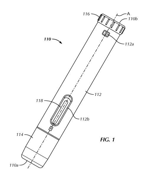
retaining the nut in the
initial position and a stop engaging the nut in a fired position, a distance
between the latch arm and
the stop being fixed. In one embodiment, the volume setting mechanism includes
a retainer and a
latch and the firing mechanism includes a ram and a biasing member, the latch
being coupled
between the biasing member and the ram, the latch being retained against a
force of the biasing
member in an initial position by the retainer. In a further embodiment, the
injection device
comprises a stop having a plurality of axially extending and radially
projecting slots each extending
2
CA 02973592 2017-07-11
WO 2016/118688 PCT/US2016/014217
a different axial depth, wherein the ram includes a wing extending radially
from the ram and
configured to engage one of the plurality of slots in a fired position.
[0011] In one embodiment, the stop and the retainer are integrally
connected. In one
embodiment, the dose setting mechanism is rotatably coupled to the ram to
radially align the wing
with one of the plurality of slots in the initial position. In one embodiment,
the ram includes a prime
screw threadably coupled to the end of the ram, the prime screw configured to
couple the ram to a
piston. In one embodiment, the ram remains in contact with the piston
independent of the position
of the dose setting mechanism. In one embodiment, the latch includes a
plurality of axially spaced
indentations each configured to engage with a projection of the retainer. In a
further embodiment,
the injection device comprises a guard that is slideably coupled to the
housing, wherein the guard
includes a sidewall configured to prevent radial motion of the retainer in the
initial position and an
aperture in the sidewall configured to allow radial motion of the retainer in
a retracted position.
100121 In one embodiment, the ram is rotatably fixed and axially moveable
relative to the dose
setting mechanism. In one embodiment, the dose setting mechanism includes a
shaft extending
partially into and radially keyed with an inner shaft of the ram in the
initial position and a fired
position. In one embodiment, the latch is axially fixed and rotatably moveable
relative to the ram.
In one embodiment, the firing mechanism includes a spring and the position of
the spring being
independent from the position of the dose setting mechanism. In one
embodiment, the dose setting
mechanism includes a knob rotatably coupled to the housing. In a further
embodiment, the injection
device comprises a guard slideably coupled to the housing and configured to
extend axially past the
injection conduit and lock relative to the housing after removing the
injection conduit from the
patient.
100131 In one embodiment, the injection conduit comprises a needle. In a
further embodiment,
the injection device comprises a syringe containing the fluid reservoir,
wherein the needle is fixed to
the syringe. In one embodiment, the injection device is configured to prevent
resetting after the
firing mechanism is actuated so as to prevent a subsequent injection of the
medicament by the
injection device, thereby configuring the injection device as a single-use
injector. In a further
embodiment, the injection device comprises a safety cap coupled to a distal
end of the housing, the
safety cap being coupled to the firing mechanism such that decoupling the
safety cap from the
housing allows the firing mechanism to advance a predetermined distance
relative to the fluid
reservoir to prime the fluid reservoir. In one embodiment, actuating the dose
setting mechanism
advances the firing mechanism a predetermined distance relative to the fluid
reservoir to prime the
3
CA 02973592 2017-07-11
WO 2016/118688 PCT/US2016/014217
fluid reservoir. In one embodiment, the firing mechanism is configured to
deliver each of the
selected fraction of the one of the plurality of volumes of medicament over a
generally equal amount
of time as compared to one another. In one embodiment, the fraction is only
greater than or equal to
0.5. In one embodiment, the selected fraction results in a residual volume
remaining in the fluid
reservoir after delivery of 0.18 ml or less.
[0014] In another embodiment, there is an injection device for injecting
medicament in a patient
comprising: a firing mechanism having an actuator and configured to be
selectively preset during
assembly to one of a plurality of positions based on a maximum volume of
medicament to be
delivered to the patient; and a dose setting mechanism configured to be
selectably adjusted upon use,
independent of the preset of the firing mechanism, to select a fraction of the
maximum volume of
medicament to be delivered to the patient.
[0015] In another embodiment there is an injection device for injecting
medicament in a patient
comprising: a housing configured to house a fluid container having a piston
and a fluid reservoir
having one of a plurality of volumes of medicament, the fluid container
including an injection
conduit fluidly coupled to the fluid reservoir defining a fluid pathway from
the fluid reservoir to the
patient; a ram coupled to the piston and configured to expel the medicament
from the fluid reservoir
through the injection conduit; a spring biasing the ram toward the fluid
container in an initial
position; a nut threadably coupled to the ram, the nut having a plurality of
ring shaped grooves or
projections; a latch fixed relative to the housing and engaging a
predetermined one of the plurality of
ring shaped grooves or projections to retain the ram in one of a plurality of
axial positions against a
force of the spring in the initial position, the nut being rotatable relative
to the latch in the initial
position; and a dose setting knob rotatably coupled to the housing and
rotatably fixed and axially
moveable relative to the ram in the initial position.
[0016] In another embodiment there is an injection device for injecting
medicament in a patient
comprising: a housing configured to house a fluid container having a piston
and a fluid reservoir
having one of a plurality of volumes of medicament, the fluid container
including an injection
conduit fluidly coupled to the fluid reservoir defining a fluid pathway from
the fluid reservoir to the
patient; a ram coupled to the piston and configured to expel the medicament
from the fluid reservoir
through the injection conduit, the ram having a radially extending wing; a
latch axially fixed and
rotatably moveable relative to the ram, the ram having a plurality of radial
features; a spring biasing
the latch toward the fluid container in an initial position; a retainer fixed
relative to the housing and
engaging a predetermined one of the plurality of radial features to retain the
ram in one of a plurality
4
CA 02973592 2017-07-11
WO 2016/118688 PCT/US2016/014217
of axial positions against a force of the spring in the initial position; a
stop having a plurality of
axially extending and radially projecting slots each extending a different
axial depth, the ram being
rotatable to align the wing with one of the plurality of slots in the initial
position and the wing
configured to engage the one of the plurality of slots in a fired position;
and a dose setting knob
rotatably coupled to the housing, the ram being rotatably fixed and axially
moveable relative to the
dose setting knob
[0017] In another embodiment there is a method for assembling an
injection device comprising:
inserting a fluid container having a fluid reservoir including one of a
plurality of volumes of
medicament into a housing, the fluid container including an injection conduit
fluidly coupled to the
.. fluid reservoir defining a fluid pathway from the fluid reservoir to the
patient; setting a volume
setting mechanism based on a size of the one of the plurality of volumes of
the medicament;
coupling the volume setting mechanism to a firing mechanism; and coupling the
firing mechanism
to the fluid reservoir, the firing mechanism configured to expel the
medicament from the fluid
reservoir through the injection conduit, the firing mechanism being coupled to
a dose setting
.. mechanism configured to select all or a fraction of the one of the
plurality of volumes of
medicament that is injected from the injection conduit when the firing
mechanism is actuated.
[0018] In another embodiment there is an injection device for injecting
medicament in a patient
comprising: a housing configured to house a fluid reservoir; an injection
conduit fluidly coupled to
the fluid reservoir defining a fluid pathway from the fluid reservoir to the
patient; a firing
mechanism coupled to the fluid reservoir and configured to expel the
medicament from the fluid
reservoir through the injection conduit; and a safety cap coupled to a distal
end of the housing, the
safety cap being coupled to the firing mechanism such that decoupling the
safety cap from the
housing allows the firing mechanism to advance a predetermined distance
relative to the fluid
reservoir to prime the fluid reservoir.
BRIEF DESCRIPTION OF THE SEVERAL VIEWS OF THE DRAWINGS
[0019] The following detailed description of embodiments of the injection
device having
variable dosing will be better understood when read in conjunction with the
appended drawings of
exemplary embodiments. It should be understood, however, that the invention is
not limited to the
precise arrangements and instrumentalities shown.
[0020] In the drawings:
5
CA 02973592 2017-07-11
WO 2016/118688 PCT/US2016/014217
[0021] Fig. 1 is a side view of an injection device in accordance with an
exemplary embodiment
of the present invention;
[0022] Fig. 2 is an exploded perspective view of the injection device of
Fig. 1;
[0023] Fig. 3A is a first side view of the injection device of Fig. 1;
[0024] Fig. 3B is a cross sectional side view of the injection device shown
in Fig. 3A taken
along a plane indicated by line A-A;
[0025] Fig. 3C is a second side view of the injection device of Fig. 1
turned 90 degrees from the
view shown in Fig. 3A;
[0026] Fig. 3D is a cross sectional side view of the injection device
shown in Fig. 3C taken
along a plane indicated by line B-B;
[0027] Fig. 3E is a cross sectional top view of the injection device
shown in Fig. 3C taken along
a plane indicated by line 3E-3E;
[0028] Fig. 4A is a second side view of the injection device of Fig. 1;
[0029] Fig. 4B is a cross sectional side view of the injection device
shown in Fig. 4A taken
.. along a plane indicated by line B-B;
[0030] Fig. 4C is an enlarged cross sectional side view of a portion of
the injection device
shown in Fig. 4B within the circled area;
[0031] Fig. 4D is an enlarged cross sectional side view of a portion of
the injection device
shown in Fig. 4C within the circled area;
[0032] Fig. 5A is a first side view of the injection device of Fig. 1 shown
with the housing
removed and in the un-primed position;
[0033] Fig. 5B is a second side view of the injection device of Fig. 1
shown with the housing
removed, turned 90 degrees from the first side view shown in Fig. 5A and shown
in the un-primed
position,
[0034] Fig. 5C is a cross sectional side view of the injection device shown
in Fig. 5B taken
along a plane indicated by line B-B;
[0035] Fig. 5D is a second side view of the injection device of Fig. 1
shown in the primed
position;
[0036] Fig. 5E is a cross sectional side view of the injection device
shown in Fig. 5D taken
along a plane indicated by line C-C;
[0037] Fig. 5F is a top view of the injection device shown in Fig. 5D;
[0038] Fig. 6A is a side view of the injection device of Fig. 1 shown in
the initial position;
6
CA 02973592 2017-07-11
WO 2016/118688 PCT/US2016/014217
[0039] Fig. 6B is a cross sectional side view of the injection device
shown in Fig. 6A taken
along a plane indicated by line I-I;
[0040] Fig. 7A is a side view of the injection device of Fig. 1 shown in
the minimum dose
position;
[0041] Fig. 7B is a cross sectional side view of the injection device shown
in Fig. 7A taken
along a plane indicated by line A-A;
[0042] Fig. 8A is a side view of the injection device of Fig. 1 shown in
the insertion position,
[0043] Fig. 8B is a cross sectional side view of the injection device
shown in Fig. 8A taken
along a plane indicated by line J-J;
[0044] Fig. 9A is a side view of the injection device of Fig. 1 shown in
the released position;
[0045] Fig. 9B is a cross sectional side view of the injection device
shown in Fig. 9A taken
along a plane indicated by line K-K;
[0046] Fig. 10A is a side view of the injection device of Fig. 1 shown in
the fired position;
[0047] Fig. 10B is a cross sectional side view of the injection device
shown in Fig. 10A taken
along a plane indicated by line L-L;
[0048] Fig. 11A is a side view of the injection device of Fig. 1 turned
90 degrees from the side
view of Fig. 10A;
[0049] Fig. 11B is a cross sectional side view of the injection device
shown in Fig. 11A taken
along a plane indicated by line M-M;
[0050] Fig. 12A is a side view of the injection device of Fig. 1 shown in
the locked out position;
[0051] Fig. 12B is a cross sectional side view of the injection device
shown in Fig 12A taken
along a plane indicated by line N-N;
[0052] Figs. 13A-13C are views of the injection device of Fig. 1 shown in
the initial position
with the housing removed;
[0053] Figs. 14A-14C are views of the injection device of Fig. 1 shown in
the insertion position
with the housing removed;
[0054] Figs. 15A-15C are views of the injection device of Fig. 1 shown in
the released position
with the housing removed;
[0055] Figs. 16A-16C are views of the injection device of Fig. 1 in the
fired position with the
housing removed;
[0056] Fig. 17 is an illustration of the mechanical advantage of the
latch of the injection device
of Fig. 1;
[0057] Figs. 18A-18D are various views of a ram of the injection device
of Fig. 1;
7
CA 02973592 2017-07-11
WO 2016/118688 PCT/US2016/014217
[0058] Figs. 19A and 19B are side views of an injection device in
accordance with an exemplary
embodiment of the present invention;
[0059] Figs. 19C and 19D are side cross sectional views of the injection
device of Figs. 19A and
19B respectively;
[0060] Fig. 20A is a first exploded perspective view of the injection
device of Fig. 19A;
[0061] Fig. 20B is a second exploded perspective view of the injection
device of Fig. 19A;
[0062] Figs. 21A-21C are various side views of the latch, ram and slot
stop of the injection
device of Fig. 19A;
[0063] Figs. 22A-22F are various views of the slot stop of the injection
device of Fig. 19A,
[0064] Fig. 23 includes various views of the ram and the ram and dose knob
assembly of the
injection device of Fig. 19A;
[0065] Figs. 24A-24E are various side and perspective views of the
injection device of Fig. 19A
with the housing and other components removed in the initial, untriggered
position;
[0066] Figs. 25A-25E are various side and perspective views of the
injection device of Fig. 19A
with the housing and other components removed in the insertion or retraction
position;
[0067] Figs. 26A-26D are various side and perspective views of the
injection device of Fig. 19A
with the housing and other components removed in the triggered position;
[0068] Figs. 27A-27D are various side and perspective views of the
injection device of Fig. 19A
with the housing and other components removed in the locked out position;
[0069] Figs. 28A-28C are various views of the ram and slot stop of the
injection device of Fig
19A shown in the minimum dose setting before the dose is delivered;
[0070] Fig. 29 is a perspective view of the ram and slot stop of Figs. 28-
28C shown after the
dose is delivered,
[0071] Figs. 30A-30C are various views of the ram and slot stop of the
injection device of Fig.
19A shown in the maximum dose setting before the dose is delivered;
100721 Figs. 31A-31B are side and side cross-sectional views respectively
of the ram and slot
stop of Figs. 30A-30C shown after the dose is delivered;
[0073] Fig. 32 is a perspective view of a safety cap having a spacer for
use with the injection
device of Fig. 19A;
[0074] Figs. 33A-33D are cross sectional side views of the injection device
of Fig. 19A having
the safety cap shown in Fig. 32;
[0075] Figs. 34A and 34B are cross sectional side views of on the
injection device of Fig. 19A
having a priming release pin;
8
CA 02973592 2017-07-11
WO 2016/118688 PCT/US2016/014217
[0076] Figs. 35a and 35b are cross sectional sketches of the latch, slot
stop and guard of the
injection device of Fig. 19A illustrating a priming configuration;
100771 Fig. 36 is a side cross sectional sketch of the injection device
of Fig. 19A having an
expandable ram for priming;
[0078] Fig. 37 is a perspective view of a latch for an injection device in
accordance with an
exemplary embodiment of the present invention;
[0079] Figs. 38A and 38B are side views of a lock-out system for an
injection device in
accordance with an exemplary embodiment of the present invention with the
outer housing removed
and shown in an initial position;
[0080] Figs. 39A and 39B are side views a guard of the injection device of
Figs. 38A and 38B;
[0081] Fig. 40 is an enlarged side view of the front retainer retaining
the guard shown within
circle A of Fig. 38A;
[0082] Figs. 41A and 41B are side views of a sleeve of the injection
device of Figs. 38A and
38B;
[0083] Fig. 42 is a side view of the front retainer and guard of Fig. 40
shown in a release
position after the dose has been delivered; and
[0084] Figs. 43A and 43B are side views of the guard, sleeve and front
retainer and the guard
and the sleeve respectively of the injection device of Figs. 38A and 38B
rotated 90 degrees from the
view shown in Fig. 42 and with the guard extended and in the locked out
position.
DETAILED DESCRIPTION OF THE INVENTION
[0085] Referring to the drawings in detail, wherein like reference
numerals indicate like
elements throughout, there is shown in Figs. 1-18D an injection device,
generally designated 110, a
first exemplary embodiment of the present invention. Various embodiments of
the injection device
110 are described in further detail below in reference to the exemplary
embodiment shown in the
figures.
[0086] The injection device 110 is configured to deliver a selected
amount of one of a plurality
of predetermined volumes of medicament to a patient The injection device 110
is assembled using
one of a plurality of fluid reservoirs and the dose that is ultimately
delivered to the patient is equal to
or less than the full amount contained in the injection device 110. This
allows for the injection
device 110 to accept fluid cartridges, prefilled syringes or similar
containers being filled to different
volumes and/or multiples sizes of fluid containers and then allows for the
user to select how much of
9
WO 2016/118688 PCT/US2016/014217
the fluid in the fluid container to deliver. Such flexibility allows for one
device to be adapted for
multiple medicament volumes and ultimately reduces the amount of wasted
medicament.
100871 For example, a typical injection device may have a volume of 1.0
ml to encompass the
range of potential dosages needed. A patient who is provided a 1.0 ml device
but only needs a
dosage of 0.5 ml, would leave a residual volume of 0.5 ml in the discarded
device. Instead, the
patient, requiring a dosage of 0.5 ml, can be provided a 1.0 ml injection
device 110 containing 0.6
ml of fluid, resulting in a residual volume of only 0.1 ml in the discarded
device. By allowing
adjustment of the volume, the manufacturer can easily set the injection device
110 to one of a
plurality of volumes to divide up the range of dosages selectable by a patient
and reduce the amount
of residual fluid left in the discarded device.
100881 The injection device 110 includes an actuator for driving fluid
from the injection device
110 into the patient. In some embodiments, the actuator is automatically
actuated as a result of
positioning the injection device 110 relative to the skin surface, also
referred to as an auto-injection
device. The injection device 110 may include a needle. In other embodiments,
the injection device
does not include a needle and the injection port of the fluid chamber
preferably defines a fluid
pathway in fluid communication with the fluid chamber for injecting medicament
as a jet from the
chamber through the port to the injection location. An example of a suitable
needle-free jet nozzle
arrangement is disclosed in U.S. Pat. No. 6,309,371.
[0089] As disclosed in further detail below, in some embodiments, the
injection device 110
includes a firing mechanism having an actuator, a volume setting mechanism
configured to be
selectively preset during assembly to one of a plurality of positions based on
a maximum volume of
medicament to be delivered to the patient (e.g., one of a 0.4 ml, 0.6 ml, 0.8
ml or 1.0 ml prefilled
syringe) and a dose setting mechanism configured to be selectably adjusted
upon use, independent
of the preset of the volume setting mechanism, to select a fraction of the
maximum volume of
medicament to be delivered to the patient (e.g., a 0.2 ml to 0.4 ml dose for a
0.4 ml syringe).
[0090] Referring to Fig. 1, the injection device 110 may include a
housing 112. The housing
112 extends along a longitudinal axis A and is configured to be held in one
hand of a patient or
caregiver to deliver the dose of medicament to the patient. In one embodiment,
the housing 112 is
cylindrical. In other embodiments, the cross sectional shape of the housing
112 is elliptical,
triangular, square or any other desired shape. The housing 112 may include one
or more windows
112a, 112b for viewing components of the injection device 110 contained within
the housing 112.
The windows 112a, 112b may be covered with a transparent material. Windows
112a, 112b may
CA 2973592 2018-11-16
CA 02973592 2017-07-11
WO 2016/118688 PCT/US2016/014217
allow the viewing of the fluid reservoir 118 within the housing 112. The
window 112a, 112b may
also allow viewing of the preset volume that has been chosen. In another
embodiment, the window
112a, 112b allows viewing that the injection device 110 is ready for use. In
another embodiment,
the window 112a, 112b allows viewing that the injection is complete. Other
uses of a window to
allow viewing internal aspects of the injection device are anticipated. In an
embodiment, the
window 112a, 112b allows viewing of injection device internal components that
assist in
administering an injection. In one embodiment, the housing 112 is comprised
partially or entirely
of a transparent material.
100911 Referring to Fig. 3B, the housing 112 is configured to house a
fluid reservoir 118 having
one of a plurality of volumes of medicament. The desired volume of the fluid
reservoir 118 is
selected before assembling the injection device 110. In one embodiment, the
desired volume of the
fluid reservoir 118 is based on the desired maximum dose that the patient will
be able to inject. In
one embodiment, the injection device 110 is configured to receive one sized
container or syringe
having a fluid reservoir 118 configured to accommodate a plurality (e.g.,
four) different maximum
volumes for injection. In other embodiments, the injection device 110 is
configured to receive a
fluid reservoir configured to accommodate two, three, or five or more
different maximum volumes
for injection. In other embodiments, the injection device 110 is configured to
receive one of four
differently sized containers having a fluid reservoir 118. In other
embodiments, the injection device
110 is configured to receive one of two, three, five or more differently sized
containers having fluid
reservoirs 118. In one embodiment, the fluid reservoir 118 contains one of 0.4
ml, 0.6 ml, 0.8 ml, or
1.0 ml of medicament. In other embodiments, the fluid reservoir 118 contains
other amounts of
medicament such as one or more of the following amounts: 004 ml, 0.05 ml, 0.06
ml, 0.07 ml, 0.08
ml, 0.09 ml, 0.1 ml, 0.2 ml, 0.3 ml, 0.4 ml, 0.5 ml, 0.6 ml, 0.7 ml, 0.8 ml
0.9 ml, 1.0 ml, 1.1 ml, 1.2
ml, 1.3 ml, 1.4 ml, 1.5 ml, 1.6 ml, 1.7 ml, 1.8 ml, 1.9 ml, 2.0 ml, greater
than 2.0 ml, less than 0.010
ml and any amount between these numbers. In one embodiment, the fluid
reservoir 118 includes a
prefilled syringe having a piston 120 forming a sliding seal at a proximal
end. An injection conduit
122 is fluidly coupled to the fluid reservoir defining a fluid pathway from
the fluid reservoir to the
patient. In one embodiment, the injection conduit 122 is a needle. The needle
122 may be staked to
the prefilled syringe.
100921 Referring to Fig. 3B, the needle 122 may be covered by a needle cap
124 in the stowed or
initial position. The needle cap 124 may include an elastomeric material for
sealing and protecting
the needle 122 in the initial position. Referring to Fig. 1, the injection
device 110 may further or
alternatively include a safety cap 114 that is releaseably coupled to a distal
end 110a of the injection
11
CA 02973592 2017-07-11
WO 2016/118688 PCT/US2016/014217
device 110. The safety cap 114 covers the injection conduit 118 in the initial
position to prevent
contamination and accidental needle sticks or actuation of the actuator. The
safety cap 114 may be
coupled to the needle cap 124 such that removing the safety cap 114 from the
housing 112 also
strips the needle cap 124 from the needle 122 and exposes the needle 122.
[0093] The injection device 110 may include a firing mechanism coupled to
the fluid reservoir
118 and configured to expel the medicament from the fluid reservoir 118
through the injection
conduit 122 (see Fig. 3B). The firing mechanism may include an actuator such
as a biasing member
126. In one embodiment, the biasing member 126 includes a compression spring.
In another
embodiment, the actuator is pneumatically driven. The biasing member 126 may
be operatively
associated with a ram 128 extending along the longitudinal axis A. The ram 128
may include a
keyed proximal end 128a and one or more male or female threads 128b. The ram
128 may include a
pair of diametrically opposed threadless portions 128e extending along the
length of the ram 128
(see Figs. 18A-18D). In one embodiment the threadless portion 128e may serve
as a keyed feature
to transfer torque or provide location to an adjacent component. The
threadless portions 128e may
be recessed relative to the threads 128b to allow for a flash or other
manufacturing artifact to exist
on the threadless portion 128e without interfering with the use of the threads
128b. The ram 128
may be coupled to the fluid reservoir 118 such that the biasing member 126
urges the ram 128 to
compress the fluid reservoir 118 and deliver the medicament to the patient
through the injection
conduit 122. In one embodiment, the ram 128 is coupled to the piston 120. The
ram 128 may
include a projection 128c extending distally for supporting the engagement
between the ram 128 and
the piston 120 (see Fig. 3B).
[0094] Referring to Figs. 4A-4D, the volume setting mechanism may be set
to provide the one
of the plurality of volumes of medicament. The volume setting mechanism may
include a nut 130
that is releaseably retained in the axial direction against a force of the
biasing member 126 in an
.. initial position by a latch 132 (see Fig. 3B). The latch 132 may include a
projection 132a that
engages a corresponding indent 130a in the nut 130 to prevent axial movement
of the nut 130 in the
initial position.
100951 The nut 130 may include a plurality of indentations 130a each
configured to engage with
the projection 132a of the latch. Each of the plurality of indentations may be
axially spaced from
one another. Each of the plurality of indentations 130a of the nut 130 may
include a ring shaped
groove extending circumferentially around the nut 130. The nut 130 may be
rotatable relative to the
latch 132. In some embodiments, providing ring shaped grooves and allowing the
nut 130 to rotate
relative to the latch 132 allows for the dose setting mechanism 116 to rotate
the ram 128 relative to
12
CA 02973592 2017-07-11
WO 2016/118688 PCT/US2016/014217
the nut 130 and therefore axially move the ram 128 as discussed further below.
During assembly of
the injection device 110, the nut 130 is configured to couple to the latch 132
in one of a plurality of
positions along an axial length of the nut 130, each of the plurality of
positions along the axial
length of the nut 130 corresponding to one of the plurality of volumes of
medicament for the firing
mechanism to expel.
100961 The nut 130 may be configured to engage a stop fixed relative to
the fluid delivery device
110 at the end of the delivery stroke as discussed below. As a result, the
distance the ram 128
extends distally from the nut 130, in some embodiments, is set to correspond
to the volume of the
fluid reservoir 118 (e.g., the axial distance between the piston 120 and the
nut 130). For example,
the position of the latch 132 relative to the nut 130 in the position
illustrated in Figs. 4B-4D
corresponds to a volume of a 0.6 ml fluid reservoir 118. If a 0.4 ml fluid
reservoir 118 is used, then
the nut 130 may be rotated distally down the ram 128 until the next higher
indent 130a of the nut
130 aligns with the projection 132a of the latch 132. If a 0.8 ml fluid
reservoir 118 is used, then the
nut 130 may be rotated proximally up the ram 128 until the next lower indent
130a of the nut 130
aligns with the projection 132a of the latch 132.
100971 The latch 132 may include a sleeve 132d surrounding the nut 130
and axially fixed
relative to the fluid reservoir 118. The latch 132 may include a pivot arm
132c that is pivotably
connected to the sleeve 132d and configured to radially move the projection
132a out of the axial
path of the nut 130 in the firing or released position (see Fig. 9B). In one
embodiment, the pivot
arm 132c is prevented from pivoting in an initial position by a radial stop
140e (see Fig. 2). The
latch 132 may include a slanted surface 132b that engages with a corresponding
slanted surface
140d in the released position (see also Fig. 17) Once the latch 132 is
disengaged from the nut 130,
the nut 130 and the threadably engaged ram 128 are released axially and fired
distally by the biasing
member 126. In other embodiments, the latch 132 and nut 130 have the reverse
mating relationship
described above such that the latch 132 includes a feature that engages with
one of a plurality of
projections from the nut 130.
100981 Referring to Fig. 4B, the direct force of the biasing member 126
upon triggering may be
borne by the latch 132. In an embodiment, the latch 132 includes a stop 132e
to attenuate the shock
resulting from the stoppage of the firing mechanism at the termination of the
injection stroke. The
stop 132e may be a radially inwardly extending flange. At the end of delivery
stroke (see Figs. 9B
and 10B) the nut 130 may engage the stop 132e. In one embodiment, the stop
132e includes a
resilient feature. In one embodiment, the resilient feature of the stop 132e
includes a spring. In
another embodiment, the resilient feature of the stop 132e includes an
elastomeric washer.
13
CA 02973592 2017-07-11
WO 2016/118688 PCT[US2016/014217
100991 In one embodiment, setting the volume by coupling the nut 130 to the
latch 132 at one of a
plurality of locations results in an adjustment of the spring force by biasing
member 126. By
moving the nut 130 axially relative to the latch 132 to set the volume, the
biasing member 126 may
be more compressed for the larger volumes and less compressed for the smaller
volumes. The rate
of delivery for a larger dose may therefore be higher than the rate of
delivery for a smaller dose
resulting in a generally equal amount of time to deliver each dose In some
embodiments, the
delivery time is not equal for each dose but closer to being equal than if the
rate of delivery was
instead constant. Referring to Table 1 below for example, a dose of 1.0 ml may
be delivered in
approximately 7-10 seconds and a dose of 0.6 ml may be delivered in
approximately 6-9 seconds.
Such a configuration, where the variability between delivery times for each
dose is minimized, may
be desirable for compliance. For example, a patient who starts a treatment at
a lower volume may
be accustomed to waiting a certain amount of time to deliver a dose and be
inclined to wait the same
amount of time even if the treatment is adjusted to a higher volume. An amount
of spring decay
may be selected such that any differences in injection time between volumes do
not result in
.. improper use of the device.
100100]
Range of delivery times
Diiivered" "
Injectrni time
(m1) range(see)
141 7- 10
OA 7 - 9
(1:6 6- 8
gigH1OW (t4 5- 8
0,1 4 - 7
R" :6
[00101] Table 1
[00102] It may be desirable to provide a spring with a spring force
decay curve where such
.. that the difference in injection time between the volumes is such that the
user does not perceive a
significant difference.
[00103] In another embodiment, rather than or in addition to the nut
130 having a plurality of
predetermined positions, the volume setting mechanism includes a ram extension
(not shown)
threadably coupled to the ram 128. The ram extension may be configured to
extend the length of the
ram 128 to a plurality of axial positions during assembly corresponding to one
of the plurality of
volumes of medicament for the firing mechanism to expel.
14
CA 02973592 2017-07-11
WO 2016/118688 PCT[US2016/014217
[00104] Referring to Fig. 2, the injection device 110 may include a dose
setting mechanism 116
configured to select a fraction of the one of the plurality of volumes of
medicament that is injected
from the injection conduit 122 when the firing mechanism is actuated. The dose
setting mechanism
116 may include a knob rotatably coupled to the housing. In one embodiment,
the dose setting
mechanism 116 caps the proximal end of the housing 112. The dose setting
mechanism 116 may
include a grip portion 116a for grasping by the patient. The grip portion 116a
may include one or
more features such as axially extending ribs 116a for increasing the
frictional force between the dose
setting mechanism 116 and a user's hand during use. The dose setting mechanism
116 may include a
dosage level portion 116b having a plurality of dosage indicia 116e. The dose
setting mechanism
116 may include a shaft 116c for coupling to the ram 128.
[00105] Referring to Figs. 3A-3D, the dose setting mechanism 116 is rotatably
moveable relative
to the housing 112. In one embodiment, the dose setting mechanism 116 is fixed
axially relative to
the housing 112. The dose setting mechanism 116 may be rotatably fixed and
axially moveable
relative to the ram 128. The proximal end 128a of the ram 128 may have a keyed
shape that
corresponds to the shape of the inside surface 116d of shaft 116c of the dose
setting mechanism 116
such that rotating the dose setting mechanism 116 rotates the ram 128, and due
to the threaded
connection between the ram 128 and the axially retained nut 130, moves the ram
128 distally and
proximally depending on the direction of rotation. When the dose setting
mechanism 116 is rotated,
indicia 116e corresponding to the position of the ram 128 may align with the
window 112a in the
housing 112 to display the selected dosage to the patient. In one embodiment,
rotating the dose
setting mechanism 116 to move the ram 128 does not impact the position and
force on the biasing
member 126. In some embodiments, the dose setting mechanism 116 includes a
resistance and/or an
audible click between selected dosages.
[00106] Referring to Fig. 6B, the biasing member 126 such as a spring may be
uniform and
configured to not buckle. In one embodiment, there is no direct spring load on
the ram 128 from the
biasing member 126 in the initial position. This allows for the ram 128 to be
axially positioned
during dose setting without impacting the spring force allowing for the spring
force to be the same
for each different volume of medicament.
[00107] Referring to Fig. 2, the injection device 110 may configured to
prevent resetting after the
firing mechanism is actuated so as to prevent a subsequent injection of the
medicament by the
injector, thereby configuring the injection device 110 as a single-use
injector. In one embodiment,
the injection device 110 includes a guard 140 that is slideably coupled to the
housing 112. The
injection device 110 may include a biasing member 138 coupled to the guard and
configured to bias
CA 02973592 2017-07-11
WO 2016/118688 PCT/US2016/014217
the guard 140 toward a distal end 110a of the injection device 110. The guard
140 may be
configured to extend axially past the injection conduit 122. In one
embodiment, the guard 140 is
configured to extend axially past the injection conduit 122 and lock axially
relative to the housing
112 after removing the injection conduit 122 from the patient.
[00108] A sleeve 134 may be coupled to the fluid reservoir 118 The sleeve
134 may include a
pair of diametrically opposed tabs 134a extending outwardly in the radial
direction. The housing
112 may include a front retainer 136 coupled to the distal end of the housing
112. The front retainer
136 may include a pair of axially extending slots configured to receive the
tabs 134a of the sleeve
134. The safety cap 114 may releaseably couple to the front retainer 136. The
biasing member 138
may be positioned within the front retainer 136 and engage the distal end of
the sleeve 134. The
other end of the biasing member 138 may be configured to engage a flange
proximate the distal end
of the guard 140. The guard 140 may include a pair of diametrically opposed
and axially extending
slots 140c for receiving the tabs 134a. The axial range of motion of the guard
140 may be dictated
by the ends of the slots 140c of the guard 140 engaging the tabs 134a of the
sleeve 134. The guard
140 and the sleeve 134 may include one or more openings 140b, 134b
respectively for aligning with
a window 112a of the housing 112 to reveal the level of medicament in the
fluid reservoir 118. The
fluid reservoir 118 may include indicia that are visible through the window
112a so that the patient
can verify that the appropriate volume of medicament is included in the
injection device 110.
[00109] Referring to Fig. 8B, the firing mechanism may be automatically
released based on the
position of the injection conduit 122 relative to the patient. In one
embodiment, retracting the guard
140 relative to the injection conduit 122 releases the firing mechanism. In
other embodiments, the
patient must actuate a button or another feature before or after retracting
the guard 140, or in an
embodiment not including a guard 140, in order to release the firing
mechanism.
[00110] The injection device 110 may accommodate two injection volume
adjustments. This
may help to minimize the amount of unused drug. The first adjustment is set
during assembly and
sets the range of volume to be delivered (e.g., the dosing range). The dosing
range may vary
depending on the fill volume in the fluid reservoir 118. This amount may be
set as part of the
assembly process. In one embodiment, there are four configurations or SKUs.
Each SKU will
represent a maximum volume of fill to allow delivery of the maximum dose
within that SKU (e.g.,
0.8 to 1.0 ml volume delivery to the patient; 0.6 to 0.8 ml volume delivery to
the patient; 0.4 to 0.6
ml volume delivery to the patient; and 0.2 to 0.4 ml volume delivery to the
patient). The second
adjustment is set by the user prior to injecting the medicament. The second
volume adjustment sets
the dose, a fraction of the volume in the fluid reservoir 118, and this dose
to be delivered within the
16
CA 02973592 2017-07-11
WO 2016/118688 PCT/US2016/014217
range allowed by the injection device 110. In one embodiment, the user may
adjust the dose, up and
down, until the injection is delivered.
[00111] Referring to Figs. 5C-5F, the injection device 110 may be pre-primed
for the user. In
one embodiment, priming the injection device 110 allows for placing the ram
128 in a known
.. position relative to the piston 120. Priming may be used to reduce an
initial gap between the ram
128 and the piston 120 and/or compression in the piston 120 to allow for tight
control of the dose
expelled during triggering. Since the ram 128 moves a fixed (controlled based
on the dose selected)
displacement, minimizing the variability associated with the starting position
of the ram 128 and
controlling the end position of the ram 128 allows for greater accuracy of the
delivered dose. Also,
by providing a device that is already primed, there may be greater assurance
that the patient will get
the correct dosing by eliminating a step that the user might have to do and
therefore eliminate an
opportunity for the user to get this wrong.
[00112] The injection device 110 may be designed for assembly that eliminates
the priming step.
A filling process may be utilized to minimize air bubble in the fluid
reservoir 118. Once the fluid
reservoir 118 is inserted into a front assembly, including the safety cap 114,
the front retainer 136,
the guard 140 and the sleeve 134, is coupled with a middle assembly including
the ram 128, the nut
130 and the latch 132. The connection between the distal end 128c of the ram
and the piston 120
may be fully secured by rotating the nut 130 relative to the ram 128. The nut
130 may include one
or more keyed features 130b (see Fig. 103b) such as a radially extending slot
for coupling to a tool.
Once the ram 128 and stopper 120 are sufficiently coupled, a rear assembly
including the housing
114 may be positioned over the middle assembly and coupled to the front
assembly and the dose
mechanism 116 and biasing member 126 may be coupled to the middle assembly and
the housing.
[00113] In some embodiments, the injection device 110 is primed by the user.
Syringes are
commonly supplied to autoinjector manufacturers in a 'drug-prefilled' state.
The prefilling process
fills the syringe with drug, and may use various methods including a vacuum
process that attempts
to remove as much air as possible inside the syringe chamber before a
plug/stopper is placed, sealing
the syringe. Bubble priming, whereby all or most of the air is expelled from
the syringe chamber
through the needle prior to injection, is extremely common in manual
injections: a bubble in an
intravenous injection can cause an air embolism in a patient. Unfortunately,
bubble priming is not
as simple in an autoinjector and the presence of an air bubble is detrimental
to the accuracy &
precision of an autoinjector's drug delivery mechanism, which commonly relies
upon advancing a
ram abutted to the piston a tightly controlled travel distance. The bubble
cannot be removed
17
CA 02973592 2017-07-11
WO 2016/118688 PCT/US2016/014217
(primed) from the syringe without removing the needle cap resulting in a
breach of the sterile
barrier.
[00114] When an appreciable force is applied to a syringe piston during an
injection, any bubbles
remaining trapped within the syringe will compress, or displace ejected fluid
decreasing the injected
volume. This is due to pressure induced by the ram, the incompressible nature
of liquids, and
compressibility of gas. A steady-state pressure equilibrium is then reached
while the liquid drug is
ejected until the ram reaches the end of its stroke. At the end of the ram
stroke, any previously
compressed gasses will expand to equilibrium with the ambient. The rate upon
which the gas
expands is variable and dependent upon the ram force, the viscosity of the
liquid, bubble size, needle
lumen size and length, and the ambient pressure. As the bubble pressure
approaches ambient, the
rate of fluid expulsion decays, increasing injection time (e.g., preferably
less than 10 seconds) for
injectors with combined viscous drug liquid and small needle lumens. As
delivered volume is
related to the travel of the syringe plunger, the amount of liquid drug that
is encompassed within this
travel distance is required to be constant to allow accurate dispensing of
drug.
[00115] In order to bubble prime the injection device 110, the injection
device 110 may be
configured to be primed by the user by pointing the distal end 110a upward and
advancing the ram
128 relative to the fluid reservoir 118. By pointing the distal end 110a of
the injection device 110
upward, buoyancy of the bubble positions it directly adjacent to the proximal
end of the needle 122.
Depending upon the viscosity of the liquid, a slight tapping of the injection
device 110 may be
required. In some embodiments, the bubble may be observed through the window
112b in the
housing 112.
[00116] In one embodiment, the injection device 110 is configured such that
removing the safety
cap 114 causes the ram 128 to advance a nominal predetelinined distance,
expelling the bubble and
potentially a small amount of liquid from the needle 122. For example, a
spacer may be provided
between the latch 132 and the proximal flanged end of the fluid reservoir 118.
[00117] Referring to Fig. 36, in some embodiments, the ram 128 is expanded to
preload the
piston 120. In one embodiment, the ram 128 includes two or more nesting
elements. In one
embodiment, a torsional spring 142 is nested in an outer ram 144. The
torsional spring 142 may
have a keyed rod 146 passing completely through the torsional spring, and
rotationally constrained
to the torsional spring. The keyed rod 146 may be locked by a removable
release pin 148 extending
from the distal end 110b of the injection device 110 and inserted into a keyed
slot 150 of an inner
ram 152 on the other end. The release pin may constrain the torsional spring
until use. Upon
18
CA 02973592 2017-07-11
WO 2016/118688 PCT/US2016/014217
removal, the torsional spring will rotate the inner ram relative to the outer
ram, extending the inner
ram to release the bubble (or provide a preload immediately prior to bubble
expulsion).
[00118] Annular or partially annular teeth in the nested ram elements may
interlock, (e.g.,
internal teeth on the outer cylinder/external teeth or slots on the inner
cylinder) allowing only one
way relative movement of the nested ram elements, inducing the ram 128 to
extend and preload the
piston 120. In one embodiment, instead of teeth, the nested ram elements are
internally/externally
threaded, allowing preload from rotation of a device element. In one
embodiment, the ram 128
includes a three part ram 128 comprised of both one way-tooth interaction and
threaded interactions.
[00119] The spacer or ram 128 may be coupled to the safety cap 114 such that
removing the
safety cap 114 removes the spacer or expands the ram 128 and preloading a
force onto the piston
120. In other embodiments, the user actuates a trigger such as by pulling a
pin, flipping a switch,
pushing a button, that pulls the spacer out of the loading stack or device
entirely or expands the ram
128. In one embodiment, setting the dose setting mechanism 116 automatically
preloads piston 120.
For example, instructions or indication to twist the dose setting mechanism
116 may be visible
through window 112a even to set the injection device 110 to the maximum dose.
This initial twist
of the dose setting mechanism 116 may be used to extend the ram 128 to prime
the injection device
110. The dosage indicia 116e may be oriented (rotated 180 degrees from example
shown in Fig. 1)
such that the number is readable when the distal end 110a of the injection
device 110 is pointed up.
[00120] In one embodiment, removal of the safety cap 114 allows the guard 140,
under spring
load, to extend a predetermined distance. This movement allows a second spring
loaded assembly
connected to the ram to advance a nominal distance to a predetermined set-
point, inducing an axial
preload on the piston 120 (see Figs. 32a and 32b as discussed further below).
In one embodiment,
the guard 140 is under a lower spring force than the firing mechanism such
that coupling the
priming of the injection device 110 to the guard 140 allows for the priming
force to be controlled
more precisely.
[00121] Once the safety cap 114 is removed, the fluid reservoir 118 may be
bubble primed and
ready for injection. A liquid receiver, such as a piece of absorbent material,
may be positioned
adjacent to the needle 122 toward the distal end 110a of the injection device
110 to capture any
expelled liquid drug during priming. The liquid receiver may be in
circumferential association with
the needle 122 and may be attached to the housing 112, safety cap 114 or both
(e.g., 2 pieces of
absorbent material).
[00122] Following assembly, the injection device 110 is ready for use.
Referring to Fig. 6B,
during use of an exemplary embodiment, the user is aware what volume of
medicament is provided
19
CA 02973592 2017-07-11
WO 2016/118688 PCT/US2016/014217
in the injection device 110 and may verify by looking at the fluid reservoir
118 through the window
112b in the housing (see Fig. 1). The user then selects the desired dose to be
delivered, either all or
a fraction of the volume of the fluid reservoir 118, by rotating the dose
setting mechanism 116
relative to the housing 112. The user may verify that the appropriate dosage
is selecting by viewing
the dosage amount indicated by the indi ci a visible through window 112a in
the housing (see Fig. 1).
Fig. 7B shows the injection device in a minimum dosage selection such that the
ram 128 is pulled
back from piston 120. The distance between the piston 120 and the ram 128 is
the distance that will
remain between the piston 120 and the distal end of the fluid reservoir 118.
The medicament
remaining in the fluid reservoir following the injection is not delivered and
may be discarded.
[00123] Referring to Fig. 8B, once the dosage is set, the user removes the
safety cap 114 (see Fig.
7B) from the front retainer 136 by pulling or twisting the safety cap 114
relative to the front retainer
136. Any priming is conducted if necessary, and the injection device 110 is
ready for injection. The
patient may then press the distal end of the guard 140 against their skin,
retracting the guard 140
proximally until the needle 122 penetrates the skin surface and the proximal
end 140d of the guard
140 contacts the slanted surface 132b of the latch 132.
[00124] Referring to Fig. 9B, once the proximal end 140d of the guard contacts
the slanted
surface 132b of the latch 132, the guard is further retracted to its fully
retracted position, moving the
stop 140e off of the pivot arm 132c of the latch and the proximal end 140d of
the guard forces
against the slanted surface 132b to pivot the pivot arm 132c and release the
projection 132a of the
latch 132 from the indentation 130a of the nut 130.
[00125] Referring to Fig. 10B, with the latch 132 released from the nut 130,
the biasing member
126 is no longer restrained and the ram 128 and nut 130 are fired toward the
distal end, urging the
piston 120 distally and delivering the dose of medicament to the patient
through the injection
conduit 122.
[00126] Referring to Figs. 12a and 12b, after the dose is delivered, the
housing 112 is pulled
away from the patient, pulling the needle 122 from the patient and allowing
the biasing member 138
to urge the guard 140 distally past the end of the needle 122. A retaining
member retains the guard
122 to lock the guard 140 relative to the needle 122 preventing further use of
the injection device
110. The injection device 110 may then be safely discarded.
[00127] Referring to the drawings in detail, wherein like reference numerals
indicate like
elements throughout, there is shown in Figs. 19A-35B an injection device,
generally designated 210,
a second exemplary embodiment of the present invention. Various embodiments of
the injection
device 210 are described in further detail below in reference to the exemplary
embodiment shown in
.=
WO 2016/118688 PCT/US2016/014217
the figures. One or more of the embodiments discussed in reference to the
injection device 210
described below may be combined with one or more desirable features of the
embodiments
discussed in reference to the injection device 110 described above.
1001281 The injection device 210 is configured to deliver a selected amount of
one of a plurality
of predetermined volumes of medicament to a patient. The injection device 210
is assembled using
one of a plurality of fluid reservoirs 218 and the dose that is ultimately
delivered to the patient is
equal to or less than the full amount contained in the injection device 210.
This allows for the
injection device 210 to accept a fluid cartridge, prefilled syringe or similar
container filled to
different volumes and/or accept multiples sizes of containers and allow for
the user to select how
much of the fluid in the fluid container to deliver. Such flexibility allows
for one device to be
adapted for multiple medicament volumes and ultimately reduces the amount of
wasted
medicament.
1001291 For example, a typical injection device may have a volume of 1.0 ml to
encompass the
range of potential dosages needed. A patient who is provided a 1.0 ml device
but only needs a
dosage of 0.5 ml, would leave a residual volume of 0.5 ml in the discarded
device. Instead, the
patient, requiring a dosage of 0.5 ml, can be provided a 1.0 ml injection
device 210 containing 0.6
ml of fluid, resulting in a residual volume of only 0.1 ml in the discarded
device. By allowing
adjustment of the volume, the manufacturer can easily set the injection device
210 to one of a
plurality of volumes to divide up the range of dosages selectable by a patient
and reduce the amount
of residual fluid left in the discarded device.
[00130] The injection device 210 includes an actuator for driving fluid from
the injection device
210 into the patient. In some embodiments, the actuator is automatically
actuated as a result of
positioning the injection device 210 relative to the skin surface, also
referred to as an auto-injection
device. The injection device 210 may include a needle. In other embodiments,
the injection device
does not include a needle and the injection port of the fluid chamber
preferably defines a fluid
pathway in fluid communication with the fluid chamber for injecting medicament
as a jet from the
chamber through the port to the injection location. An example of a suitable
needle-free jet nozzle
arrangement is disclosed in U.S. Pat. No. 6,309,371.
[00131] As disclosed in further detail below, in some embodiments, the
injection device 210
includes a firing mechanism having an actuator, a volume setting mechanism
configured to be
selectively preset during assembly to one of a plurality of positions based on
a maximum volume of
medicament to be delivered to the patient (e.g., one of a 0.4 ml, 0.6 ml, 0.8
ml or 1.0 ml prefilled
21
CA 2973592 2018-11-16
CA 02973592 2017-07-11
WO 2016/118688 PCT/US2016/014217
syringe) and a dose setting mechanism configured to be selectably adjusted
upon use, independent
of the preset of the volume setting mechanism, to select a fraction of the
maximum volume of
medicament to be delivered to the patient (e.g., a 0.2 ml to 0.4 ml dose for a
0.4 ml syringe).
[00132] Referring to Figs. 19A-19B, the injection device 210 may include a
housing 212. The
housing 212 extends along a longitudinal axis A and is configured to be held
in one hand of a patient
or caregiver to deliver the dose of medicament to the patient. In one
embodiment, the housing 212
is cylindrical. In other embodiments, the cross sectional shape of the housing
212 is elliptical,
triangular, square or any other desired shape. The housing 212 may include one
or more windows
212a, 212b for viewing components of the injection device 210 contained within
the housing 212.
The windows 212a, 212b may be covered with a transparent material. Windows
212a, 212b may
allow the viewing of the fluid reservoir within the housing 212. The window
212a, 212b may also
allow viewing of the preset volume that has been chosen. In another
embodiment, the window 212a,
212b allows viewing that the device is ready for use. In another embodiment,
the window 212a,
212b allows the viewing the injection is complete. Other uses of a window to
allow viewing
internal aspects of the injection device are anticipated. In an embodiment,
the window 212a, 212b
allows viewing of injection device internal components that assist in
administering an injection. In
one embodiment, the housing 212 is comprised partially or entirely of a
transparent material.
[00133] Referring to Figs. 19C-19D, the housing 212 is configured to house a
fluid reservoir 218
having one of a plurality of volumes of medicament. The volume of the fluid
reservoir 218 is
selected before assembling the injection device 210. In one embodiment, the
volume of the selected
fluid reservoir 218 is based on the desired maximum dose that the patient can
inject. In one
embodiment, the injection device 210 is configured to receive one sized
container or syringe having
a fluid reservoir 218 to accommodate a plurality (e.g., six) different maximum
volumes for injection.
In other embodiments, the injection device 210 is configured to receive a
container having two,
three, four, five, seven or more different maximum volumes for injection. In
other embodiments,
the injection device 210 is configured to receive six differently sized
containers having fluid
reservoirs 118. In other embodiments, the injection device 210 is configured
to receive two, three,
four, five, six, seven or more differently sized containers having fluid
reservoirs 218. In one
embodiment, the fluid reservoir 218 contains one of 0.4 ml, 0.6 ml, 0.8 ml, or
1.0 ml of medicament.
.. In other embodiments, the fluid reservoir 218 contains other amounts of
medicament such as one or
more of the following amounts: 0.04 ml, 0.05 ml, 0.06 ml, 0.07 ml, 0.08 ml,
0.09 ml, 0.1 ml, 0.2 ml,
0.3 ml, 0.4 ml, 0.5 ml, 0.6 ml, 0.7 ml, 0.8 ml 0.9 ml, 1.0 ml, 1.1 ml, 1.2 ml,
1.3 ml, 1.4 ml, 1.5 ml,
1.6 ml, 1.7 ml, 1.8 ml, 1.9 ml, 2.0 ml, greater than 2.0 ml, less than 0.010
ml and any amount
22
CA 02973592 2017-07-11
WO 2016/118688 PCT/US2016/014217
between these numbers. In one embodiment, the fluid reservoir 218 includes a
prefilled syringe
having a piston 220 forming a sliding seal at a proximal end. An injection
conduit 222 is fluidly
coupled to the fluid reservoir defining a fluid pathway from the fluid
reservoir 218 to the patient. In
one embodiment, the injection conduit 222 is a needle. The needle 222 may be
staked to the
prefilled syringe.
[00134] The needle 222 may be covered by a needle cap 224 in the stowed or
initial position
The needle cap 224 may include an elastomeric material for sealing and
protecting the needle 222 in
the initial position. The injection device 210 may further or alternatively
include a safety cap 214
that is releaseably coupled to a distal end 210a of the injection device 210.
The safety cap 214
covers the injection conduit 218 in the initial position to prevent
contamination and accidental
needle sticks or actuation of the actuator. The safety cap 214 may be coupled
to the needle cap 224
such that removing the safety cap 214 from the housing 212 also strips the
needle cap 224 from the
needle 222 and exposes the needle 222.
[00135] The injection device 210 may include a firing mechanism coupled to the
fluid reservoir
218 and configured to expel the medicament from the fluid reservoir 218
through the injection
conduit 222. The injection device 210 may include an actuator such as a
biasing member 226. In
one embodiment, the biasing member 226 includes a compression spring. In
another embodiment,
the actuator is pneumatically driven. The biasing member 226 may be
operatively associated with a
ram 228 extending along the longitudinal axis A. The ram 228 may include a
keyed shaft 228c (see
Fig. 21B). The ram 228 may be coupled to the fluid reservoir 218 such that the
biasing member 226
urges the ram 228 to compress the fluid reservoir 218 and deliver the
medicament to the patient
through the injection conduit 222. In one embodiment, the ram 228 is coupled
to the piston 220.
The ram 228 may include a prime screw 242 extending distally from the end of
the ram 228 at
selectively adjustable distances to maintain contact between the ram 228 and
the piston 220 for
priming purposes as discussed in further detail below.
[00136] Referring to Figs. 21A-21C and 22A-22F, the volume setting mechanism
may be set or
configured during assembly of the injection device 210 to properly deliver the
one of the plurality of
volumes of medicament selected as the fluid reservoir 218. The volume setting
mechanism may
include a latch 232, a slot stop or stop 230 and a retainer 230a. The retainer
230a may be configured
to retain the latch 232 relative to the slot stop 230. In one embodiment, the
latch 232 is releaseably
retained in the axial direction against a force of the biasing member 226 in
an initial position by the
retainer 230a. The latch 232 may include a radial projection such as a flange
232a configured to
engage the end of the biasing member 226 (see Fig. 19C). The latch 232 may be
axially fixed and
23
CA 02973592 2017-07-11
WO 2016/118688 PCT/US2016/014217
rotatably coupled to the ram 228. The proximal end of the ram 228 may include
a collar 228d that is
rotatably received in a corresponding ring shaped groove in the latch 232. The
slot stop 230 may be
axially and rotatably fixed relative to the fluid reservoir 218. The ram 228
may include a radially
extending wing 228b fixed to the ram 228. In other embodiments, the ram 228
includes two or more
radially extending wings. As discussed further below, the slot stop 230 may be
configured to set the
axial position of the ram 228 relative to the fluid reservoir 218 and limit
how far the ram 228 is
permitted to travel relative to the fluid reservoir 218.
[00137] Referring to Figs. 21A-21C, the latch 232 may include a plurality of
radially extending
features 232b, such as apertures, indents and/or projections, each configured
to engage with the
retainer 230a. Each of the plurality of radially extending features 232b may
be axially spaced from
one another. In one embodiment, such a configuration positions the distal end
of the ram 228
relative to the fluid reservoir 218. During assembly of the injection device
210, the retainer 230a is
configured to couple to the latch 232 in one of a plurality of positions along
an axial length of the
latch 232, each of the plurality of positions along the axial length of the
latch 232 corresponding to
one of the plurality of volumes of medicament of the fluid reservoir 218 for
the firing mechanism to
expel. In one embodiment, the latch 232 includes an additional set of radially
extending features
232b closest to the proximal end to retain the latch 232 relative to the slot
stop 230 at the end of
delivery.
[00138] Referring to Fig. 37, another embodiment of the latch 332 is shown.
The latch 332 may
include a single, radially extending feature 332b configured to engage with
the retainer 230a. In one
embodiment, the radially extending feature 332b is a window or cut-out. The
axial depth or height
of the radially extending feature 332b may be predetermined, and one of a
plurality of latches 332 is
selected based on the axial depth or height of its radially extending feature
332b. The latch 332 that
is selected will depend on the desired one of the plurality of volumes of
medicament of the fluid
reservoir 218 for the firing mechanism to expel. The latch 332 may include one
or more alignment
features 332d that engage a corresponding feature of the housing to prevent
the latch 332 from
rotating relative to the housing during firing. In one embodiment, the
alignment features 332d
include a plurality of opposed and axially spaced projections that are
configured to engage a rib
extending axially and projecting radially inward from the housing.
[00139] Referring to Figs. 21A-21C, the wing 228b of the ram 228 may be
configured to engage
a stop fixed relative to the fluid delivery device 210 at the end of the
delivery stroke as discussed
below. As a result, the distance the ram 228 extends distally from a bottom
surface 230h of the slot
stop 230, in some embodiments, is set to correspond to the volume of the fluid
reservoir 218 (e.g.,
24
CA 02973592 2017-07-11
WO 2016/118688 PCT/US2016/014217
the axial distance between the piston 220 and the bottom surface 230h of the
slot stop 230). For
example, the position of the latch 232 relative to the slot stop 230 in the
maximum position
illustrated in Figs. 21A-21C corresponds to a volume of a 1.0 ml fluid
reservoir 218. If a 0.8 ml
fluid reservoir 218 is used for example, then the slot stop 230 may be move
proximally relative to
the latch 232 to engage the projection 230c of the retainer 230a with the next
proximal radially
extending feature 232b of the latch 232 and extend the ram 228 further toward
the distal end 210a of
the injection device 210.
[00140] Referring to Figs. 22A-22F, the retainer 230a may be integrally formed
with the slot stop
230. In other embodiments, the retainer 230a is a separate component from slot
stop 230. The
retainer 230a may be a cantilever arm. In one embodiment the retainer 230a has
one or more
circumferentially extending protections to form an upside down capital letter
T or Y shape. In one
embodiment, two or more retainers 230a are provided. In one embodiment, two
diametrically
opposed retainers 230a are provided. The retainer 230a may be configured to
radially deflect inward
about an inflection point 230e. In one embodiment, inflection point 230e
includes a groove or
recess to help facility bending of the material. The retainer 230a may include
a projection 230c that
engages a corresponding radially extending feature 232b (see Fig. 21A) to
prevent axial movement
of the latch 232 in the initial position. The projection 230c may include a
sloped top surface 230d to
help facilitate translating the axial force exerted on the retainer 230a into
a radial deflection of the
retainer 230a to move the projection 230c from interfering with axial motion
of the latch 232 in the
triggered or released position.
[00141] Once the latch retainer 230a is disengaged from the latch 232, the
latch 232 and ram 228
are released axially and fired distally by the biasing member 226. In other
embodiments, the latch
232 and retainer 230a have the reverse mating relationship to the
configuration described above such
that the radially extending features 232b are protrusions that are engageable
by an indent or aperture
in the retainer 230a.
[00142] In one embodiment, setting the volume by coupling the slot stop 230 to
the latch 232 at
one of a plurality of locations results in an adjustment of the spring force
by biasing member 226.
By moving the slot stop 230 axially relative to the latch 232 to set the
volume, the biasing member
226 may be more compressed for the larger volumes and less compressed for the
smaller volumes.
The rate of delivery for a larger dose may therefore be higher than the rate
of delivery for a smaller
dose resulting in a generally equal amount of time to deliver each dose. In
some embodiments, the
delivery time is not equal for each dose but closer to being equal than if the
rate of delivery was
instead constant. Referring to Fig. 2 for example, a dose of 1.0 ml may be
delivered in
CA 02973592 2017-07-11
WO 2016/118688 PCT/US2016/014217
approximately 7-10 seconds and a dose of 0.6 ml may be delivered in
approximately 6-9 seconds.
Such a configuration, where the variability between delivery times for each
dose is minimized, may
be desirable for compliance. For example, a patient who starts a treatment at
a lower volume may
be accustomed to waiting a certain amount of time to deliver a dose and be
inclined to wait the same
amount of time even if the treatment is adjusted to a higher volume. An amount
of spring decay
may be selected such that any differences in injection time between volumes do
not result in
improper use of the device.
[00143]
Range of delivery timesDthvered Injection time
,17,440,(we) A
1.11 7- 10
E! 0.8-, 7- 9
0- 6 6- 8
mom -
Oki 0,4 5- 8
4
......... ......... 7
[00144] Table 2
[00145] It may be desirable to provide a spring with a spring force decay
curve where such that
the difference in injection time between the volumes is such that the user
does not perceive a
significant difference.
[00146] Referring to Figs. 19C-20B, the injection device 210 may include a
dose setting
mechanism 216 configured to select a fraction of the one of the plurality of
volumes of medicament
that is injected from the injection conduit 222 when the firing mechanism is
actuated. The dose
setting mechanism 216 may include a knob rotatably coupled to the housing. In
one embodiment,
the dose setting mechanism 216 caps the proximal end of the housing 212. The
dose setting
mechanism 216 may include a grip portion 216a for grasping by the patient. The
grip portion 216a
may include one or more features such as axially extending and radially
projecting ribs 216a for
increasing the frictional force between the dose setting mechanism 216 and a
user's hand during use.
The dose setting mechanism 216 may include a dosage level portion 216b having
a plurality of
dosage indicia 216e. The dose setting mechanism 216 may include a shaft 216d
for coupling to the
ram 228.
[00147] Referring to Figs. 19C-19D and 24A-24E, the dose setting mechanism 216
may be
rotatably moveable relative to the housing 212. In one embodiment, the dose
setting mechanism
216 is fixed axially relative to the housing 212. The dose setting mechanism
216 may be rotatably
26
CA 02973592 2017-07-11
WO 2016/118688 PCT/US2016/014217
fixed and axially moveable relative to the ram 228. The interior shaft 228c
(see Figs. 21B and 23)
of the ram 228 may have a keyed shape that corresponds to the shape (such as
projections 2160 of
the shaft 216d of the dose setting mechanism 216 such that rotating the dose
setting mechanism 216
rotates the ram 228, and rotates the wing 228b relative to the slot stop 230
(see Fig. 28C). When the
dose setting mechanism 216 is rotated, indi ci a 216e corresponding to the
radial position of the wing
228b may align with the window 212a in the housing 212 to display the selected
dosage to the
patient. In one embodiment, rotating the dose setting mechanism 216 to rotate
the ram 228 does not
impact the position and force on the biasing member 226. In some embodiments,
the dose setting
mechanism 216 includes a resistance and/or an audible click between selected
dosages.
[00148] Referring to Figs. 22A-22F, the slot stop 230 may include a body 230f.
The body 230f
may be held stationary with respect to the fluid reservoir 218. In one
embodiment, the body 230f
includes a hole 230g extending there through to allow the ram 228 to pass
through the slot stop 230
(see Fig. 21B). The slot stop 230 may include a plurality of axially extending
and radially
projecting slots 230b. In one embodiment, the slots 230b are open toward the
hole 230g. The slots
230b may be sized and configured to receive the wing 228b in the fired
position. The slots 230b
may have different axial depths such that the wing 228b is stopped different
distances from a bottom
surface 230h of the body 230f and therefore stops the distal end of the piston
at different distances
relative to the fluid reservoir 218. The wing 228b may include a pointed
bottom edge 228c and/or
the slot stop 230 may include pointed spaces between each of the slots 230b to
help ensure that the
wing 228b is guided into the appropriate slot 230b. In one embodiment, the
slots 230b have an
increasing axial depth from one slot 230b to an adjacent slot 230b moving
around the hole 230g. In
other embodiments, every other slot 230b has an increasing axial depth if two
diametrically opposed
wings 228b are provided, for example.
[00149] Referring to Figs. 19C-21C, the injection device 210 may be pre-primed
for the user. In
one embodiment, priming the injection device 210 allows for placing the ram
228 in a known
position relative to the piston 220. Priming may be used to reduce an initial
gap between the ram
228 and the piston 220 and/or compression in the piston 220 to allow for tight
control of the dose
expelled during triggering. Since the ram 228 moves a fixed (controlled based
on the dose selected)
displacement, minimizing the variability associated with the starting position
of the ram 228 and
controlling the end position of the ram 228 allows for greater accuracy of the
delivered dose. Also,
by providing a device that is already primed, there may be greater assurance
that the patient will get
the correct dosing by eliminating a step that the user might have to do and
therefore eliminate an
opportunity for the user to get this wrong. The injection device 210 may be
designed for assembly
27
CA 02973592 2017-07-11
WO 2016/118688 PCT/US2016/014217
that eliminates the priming step. A filling process may be utilized to
minimize air bubble in the
fluid reservoir 218. Once the fluid reservoir 218 is inserted into a front
assembly, including the
safety cap 214, the front retainer 236, the guard 240 and the sleeve 234, is
coupled with a middle
assembly including the ram 228, the latch 232 and the slot stop 230
(selectively coupled to the
desired axial position on the latch 232) which is then coupled with a rear
assembly including the
biasing member 226, the housing 212 and the dose setting mechanism 216.
[00150] After setting the volume setting mechanism and before attaching or
sealing off the dose
setting mechanism, the ram 228 may be primed. In one embodiment, the ram 228
is primed using a
prime screw 242. The prime screw 242 may be threadably attached to the ram 228
to adjust how far
axially the prime screw 242 extends from the ram 228. The prime screw 242 may
include a keyed
feature 242b such that a corresponding tool may be inserted through the shaft
228c of the ram 228 to
rotate the prime screw 242 and adjust the position of the distal end 242a of
the prime screw 242
relative to the piston 220. In one embodiment, the distal end 242a is
configured to be in contact
with the piston 220 in the initial position independent of the position of the
dose mechanism 216.
[00151] In one embodiment, the distal end 242a of the prime screw 242 is in
contact with the
piston 220 in the initial position such that the ram 228 does not move
relative to piston 220 during
triggering. By eliminating an axial space between the piston 220 and the ram
228 in the initial
position, the ram 228 may be prevented from dynamically impacting the piston
220 once the
injection device 210 has been fired, referred to as "shock loading". In some
embodiments, the
patient may feel or hear the impact between the ram 228 and the piston 220 if
there is shock loading
and/or the impact may potentially damage the syringe. In certain embodiments,
a gap between the
ram 228 and the piston 220 is provided if desired.
[00152] Referring to Figs. 32-35B, in some embodiments, the injection device
210 is primed by
the user. Syringes are commonly supplied to autoinjector manufacturers in a '
drug-prefilled' state.
The prefilling process fills the syringe with drug, and may use various
methods including a vacuum
process that attempts to remove as much air as possible inside the syringe
chamber before a
plug/stopper is placed, sealing the syringe. Bubble priming, whereby all or
most of the air is
expelled from the syringe chamber through the needle prior to injection, is
extremely common in
manual injections: a bubble in an intravenous injection can cause an air
embolism in a patient.
Unfortunately, bubble priming is not as simple in an autoinjector and the
presence of an air bubble is
detrimental to the accuracy and precision of an autoinjector's drug delivery
mechanism, which
commonly relies upon advancing a ram abutted to the piston a tightly
controlled travel distance.
28
CA 02973592 2017-07-11
WO 2016/118688 PCT/US2016/014217
The bubble cannot be removed (primed) from the syringe without removing the
needle cap resulting
in a breach of the sterile barrier.
[00153] When an appreciable force is applied to a syringe piston during an
injection, any bubbles
remaining trapped within the syringe will compress, or displace ejected fluid
decreasing the injected
volume. This is due to pressure induced by the ram, the incompressible nature
of liquids, and
compressibility of gas. A steady-state pressure equilibrium is then reached
while the liquid drug is
ejected until the ram reaches the end of its stroke. At the end of the ram
stroke, any previously
compressed gasses will expand to equilibrium with the ambient. The rate upon
which the gas
expands is variable and dependent upon the ram force, the viscosity of the
liquid, bubble size, needle
.. lumen size and length, and the ambient pressure. As the bubble pressure
approaches ambient, the
rate of fluid expulsion decays, increasing injection time (e.g., preferably
less than 10 seconds) for
injectors with combined viscous drug liquid and small needle lumens. As
delivered volume is
related to the travel of the syringe plunger, the amount of liquid drug that
is encompassed within this
travel distance is required to be constant to allow accurate dispensing of
drug.
[00154] In order to bubble prime the injection device 210, the injection
device 210 may be
configured to be primed by the user by pointing the distal end 210a upward and
advancing the ram
228 relative to the fluid reservoir 218. By pointing the distal end 210a of
the injection device 210
upward, buoyancy of the bubble positions it directly adjacent to the proximal
end of the needle 222.
Depending upon the viscosity of the liquid, a slight tapping of the injection
device 210 may be
.. required. In some embodiments, the bubble may be observed through the
window 212b in the
housing 212.
[00155] Referring to Figs. 32-33D, in one embodiment, the injection device 210
is configured
such that removing the safety cap 214 causes the ram 228 to advance a nominal
predetermined
distance, expelling the bubble from the fluid reservoir 218 and potentially a
small amount of liquid
from the needle 222. For example, a spacer 214a may be provided between the
latch 232 and the
proximal flanged end of the fluid reservoir 218. In one embodiment, the spacer
214a is a sleeve that
extends proximally from the safety cap 214 to retain the slot stop 230 a
distance G from a proximal
end of the fluid reservoir 218. Removing the spacer 214a allows the firing
mechanism, including
the ram 228, to advance the distance G and have the slot stop 230 abut against
the proximal end of
the fluid reservoir 218 or whatever feature is coupled to the proximal end of
the fluid reservoir 218
such as a bumper.
[00156] Referring to Fig. 36, in some embodiments, the ram 228 is expanded to
preload the
piston 220. In one embodiment, the ram 228 includes two or more nesting
elements. In one
29
CA 02973592 2017-07-11
WO 2016/118688 PCT/US2016/014217
embodiment, a torsional spring 142 is nested in an outer ram 144. The
torsional spring 142 may
have a keyed rod 146 passing completely through the torsional spring, and
rotationally constrained
to the torsional spring. The keyed rod 146 may be locked by a removable
release pin 148 extending
from the distal end 210b of the injection device 210 and inserted into a keyed
slot 150 of an inner
ram 152 on the other end. The release pin may constrain the torsional spring
until use Upon
removal, the torsional spring will rotate the inner ram relative to the outer
ram, extending the inner
ram to release the bubble (or provide a preload immediately prior to bubble
expulsion).
[00157] Annular or partially annular teeth in the nested ram elements may
interlock, (e.g.,
internal teeth on the outer cylinder/external teeth or slots on the inner
cylinder) allowing only one
way relative movement of the nested ram elements, inducing the ram 228 to
extend and preload the
piston 220. In one embodiment, instead of teeth, the nested ram elements are
internally/externally
threaded, allowing preload from rotation of a device element. In one
embodiment, the ram 228
includes a three part ram 228 comprised of both one way-tooth interaction and
threaded interactions.
[00158] The spacer or ram 228 may be coupled to the safety cap 214 such that
removing the
safety cap 214 removes the spacer or expands the ram 228 and preloads a force
onto the piston 220.
In other embodiments, the user actuates a trigger such as by pulling a pin 244
(see Figs. 34a-34B),
flipping a switch, pushing a button, that pulls the spacer out of the loading
stack or device entirely or
expands the ram 228. In one embodiment, setting the dose setting mechanism 216
automatically
preloads piston 220. For example, instructions or indication to twist the dose
setting mechanism 216
may be visible through window 212a even to set the injection device 210 to the
maximum dose.
This initial twist of the dose setting mechanism 216 may be used to extend the
ram 228 to prime the
injection device 210. The dosage indicia 216e may be oriented (rotated 180
degrees from example
shown in Fig. 19B) such that the number is readable when the distal end 210a
of the injection device
210 is pointed up.
[00159] Referring to Figs. 35a and 35b, in one embodiment, removal of the
safety cap 214 allows
the guard 240, under spring load, to extend a predetermined distance. This
movement allows for
one or more prime arms 230i to deflect radially inward and cause the second
spring loaded assembly
connected to the ram to advance a nominal distance to a predetermined set-
point, inducing an axial
preload on the piston 220. In one embodiment, the guard 240 is under a lower
spring force than the
firing mechanism such that coupling the priming of the injection device 210 to
the guard 240 allows
for the priming force to be controlled more precisely.
[00160] Once the safety cap 214 is removed, the fluid reservoir 218 may be
bubble primed and
ready for injection. A liquid receiver, such as a piece of absorbent material,
may be positioned
CA 02973592 2017-07-11
WO 2016/118688 PCT/US2016/014217
adjacent to the needle 222 toward the distal end 210a of the injection device
210 to capture any
expelled liquid drug during priming. The liquid receiver may be in
circumferential association with
the needle 222 and may be attached to the housing 212, safety cap 214 or both
(e.g., 2 pieces of
absorbent material).
.. [00161] Referring to Figs. 19C and 27A-27D, the injection device 210 may
configured to prevent
resetting after the firing mechanism is actuated so as to prevent a subsequent
injection of the
medicament by the injector, thereby configuring the injection device 210 as a
single-use injector. In
one embodiment, the injection device 210 includes a guard 240 that is
slideably coupled to the
housing 212. The injection device 210 may include a biasing member 238 coupled
to the guard 240
and configured to bias the guard 240 toward a distal end 210a of the injection
device 210. The
guard 240 may be configured to extend axially past the injection conduit 222.
In one embodiment,
the guard 240 is configured to extend axially past the injection conduit 222
and lock axially relative
to the housing 212 after removing the injection conduit 222 from the patient.
[00162] Referring to Figs. 20A-20B, a sleeve 234 may be coupled to the fluid
reservoir 218. The
sleeve 234 may include a pair of diametrically opposed tabs 234a extending
outwardly in the radial
direction. The housing 212 may include a front retainer 236 coupled to the
distal end of the housing
212. The front retainer 236 may include a pair of axially extending slots 236a
configured to receive
the tabs 234a of the sleeve 234. The safety cap 214 may releaseably couple to
the front retainer 236.
The biasing member 238 may be positioned within the front retainer 236 and
engage the distal end
of the sleeve 234. The other end of the biasing member 238 may be configured
to engage a flange
proximate the distal end of the guard 240. The guard 240 may include a pair of
diametrically
opposed and axially extending slots 240c for receiving the tabs 234a. The
axial range of motion of
the guard 240 may be dictated by the ends of the slots 240c of the guard 240
engaging the tabs 234a
of the sleeve 234. The guard 240 and the sleeve 234 may include one or more
openings 240b, 234b
respectively for aligning with a window 212b of the housing 212 to reveal the
level of medicament
in the fluid reservoir 218. The fluid reservoir 218 may include indicia and/or
the level of fluid
contained therein that are visible through the window 212b so that the patient
can verify that the
appropriate volume of medicament is included in the injection device 210.
[00163] Referring to Figs. 24A-27D, the firing mechanism may be automatically
released based
on the position of the injection conduit 222 relative to the patient. In one
embodiment, retracting the
guard 240 relative to the injection conduit 222 releases the firing mechanism.
In other embodiment,
the patient must actuate a button or another feature before or after
retracting the guard 240, or in an
embodiment not including a guard 240, in order to release the firing
mechanism.
31
CA 02973592 2017-07-11
WO 2016/118688 PCT[US2016/014217
[00164] The injection device 210 may accommodate two injection volume
adjustments. This
may help to minimize the amount of unused drug. The first adjustment is set
during assembly and
sets the range of volume to be delivered (e.g., the dosing range). The dosing
range may vary
depending on the fill volume in the fluid reservoir 218. This amount may be
set as part of the
assembly process. In one embodiment, there are four configurations or SKUs.
Each SKU will
represent a maximum volume of fill to allow delivery of the maximum dose
within that SKU (e.g.,
0.8 to 1.0 ml volume delivery to the patient; 0.6 to 0.8 ml volume delivery to
the patient; 0.4 to 0.6
ml volume delivery to the patient; and 0.2 to 0.4 ml volume delivery to the
patient). The second
adjustment is set by the user prior to injecting the medicament. The second
volume adjustment sets
the dose, a fraction of the volume in the fluid reservoir 218, and this dose
to be delivered within the
range allowed by the injection device 210. In one embodiment, the user may
adjust the dose, up and
down, until the injection is delivered.
[00165] Referring to Figs. 24A-24E, during use of an exemplary embodiment, the
user is aware
what volume of medicament is provided in the injection device 210 and may
verify by looking at the
fluid reservoir 218 through the window 212b in the housing (see Figs. 20A-
20B). The user then
selects the desired dose to be delivered, either all or a fraction of the
volume of the fluid reservoir
218, by rotating the dose setting mechanism 216 relative to the housing 212.
The user may verify
that the appropriate dosage is selected by viewing the dosage amount indicated
by the indicia visible
through window 212a in the housing (see Figs. 20A-20B). Figs. 28A-28C show the
injection device
in a minimum dosage selection such that the ram 228 is rotated such that the
wing 228b align with
the shallowest slot 230b. In one embodiment, the medicament remaining in the
fluid reservoir 218
following the injection is not delivered and may be discarded
[00166] Referring to Figs. 25A-25E, once the dosage is set by the user, the
user removes the
safety cap 214 from the front retainer 236 by pulling or twisting the safety
cap 214 relative to the
front retainer 236 (see Fig. 19C). Any priming is conducted if necessary, and
the injection device
110 is ready for injection. The patient may then press the distal end of the
guard 240 against their
skin retracting the guard 240 proximally until the needle 222 penetrates the
skin surface and the
aperture 240a aligns with the retainer 230a.
[00167] Referring to Figs. 25A-25E and 26A-26D, once the aperture 240a is
aligned with the
retainer 230a, the retainer 230a is radially released and the axial force of
the latch on the retainer
230a pivots the projection 230c inwardly and out of the axial path of the
latch 232 allowing the
biasing member 226 to distally extend the latch 232, causing the ram 228 to
urge the piston 220
distally and deliver the dose of medicament to the patient through the
injection conduit 222. The
32
CA 02973592 2017-07-11
WO 2016/118688 PCT/US2016/014217
shaft 216d may extend a sufficient distance in the distal direction so that
the dose setting mechanism
216 remains rotatably fixed relative to the ram 228. Since the ram 228 is
rotatably fixed by the
wing's 228b engagement with the slot stop 230, the dose setting mechanism 216
is prevented from
rotating in the fired position and ensuring that the dosage displayed through
the window 212a is the
dosage that was delivered. If the dose setting mechanism 216 did not remain
coupled to the ram 228
in the fired position, then the dose setting mechanism 216 may be able to
rotate relative to the ram
228 and cause confusion as to what dosage was delivered.
[00168] Referring to Figs. 27A-27D, after the dose is delivered, the housing
212 is pulled away
from the patient, pulling the needle 222 from the patient and allowing the
biasing member 238 to
urge the guard 240 distally past the end of the needle 222. A retaining member
retains the guard 240
to lock the guard 240 relative to the needle 222 preventing further use of the
injection device 210.
The injection device 210 may then be safely discarded. An exemplary lock-out
system is described
below.
[00169] Referring to the drawings in detail, wherein like reference numerals
indicate like
.. elements throughout, there is shown in Figs. 38A-42B a lock-out system for
an injection device,
generally designated 310, a third exemplary embodiment of the present
invention. Various
embodiments of the lock-out system are described in further detail below in
reference to the
exemplary embodiment shown in the figures. One or more of the embodiments
discussed in
reference to the lock-out system described below may be combined with one or
more desirable
features of the embodiments discussed in reference to the injection devices
110 and 210 described
above.
[00170] Referring to Figs. 38A and 40, the front retainer 336, which is
axially fixed relative to a
housing and the fluid reservoir (not shown), may initially prevent the biasing
member 338 (see Figs.
43A and 43B) from distally extending the guard 340. The guard 340 however, may
be free to retract
relative to the front retainer 336 in the proximal direction. The front
retainer 336 may include one
or more arms 336a that engage with a corresponding stop 340b of the guard 340.
In one
embodiment, the front retainer 336 includes two pairs of arms 336a (the front
pair of arms 336a
being visible in the drawings).
[00171] Referring to Figs. 38B, 39A, 41A and 41B, the injection device 310 may
include a sleeve
334 fixed relative to the front retainer 336. The sleeve 334 may include a
radial projection 334a. In
one embodiment, the sleeve 334 includes a pair of diametrically opposed radial
projections 334a
(see Fig. 41B). In the initial position, the radial projection 334a may be
positioned distally to the
end of one or more arms 340a of the guard 340. The radial projection 334a may
extend through a
33
WO 2016/118688 PCT/US2016/014217
slot 340c in the guard 340. As the guard 340 is retracted during an injection,
the slot 340c may be
slid in a proximal direction relative to the radial projection 334a.
1001721 Referring to Fig. 42, the latch may include one or more legs 332c. In
one embodiment,
the latch includes a pair of diametrically opposed legs 332c. The legs 332c
may be tapered distally.
Once the firing mechanism is actuated and the latch 332 is released, the latch
332 is fired distally by
the biasing member 326 (see Figs 38A-38B). At the end of the delivery stroke,
the legs 332c of the
latch 332 engage with the arms 336a and flex the arms 335a out of the axial
path of the stops 340b
(see Fig. 40) of the guard 340.
1001731 Referring to Figs. 43A and 43B, once the arms 336a are disengaged from
the stops 340b,
the biasing member 338 extends the guard 340 distally to cover the end of the
needle. As the guard
340 extends, the slot 340c of the guard is slid proximally relative to the
radial projection 334a. As
the guard 340 extends past the initial position of the guard 340, the arms
340a of the guard 340
extend over the radial projection 334a of the sleeve 334. As the arms 340a of
the guard 340 extend
over the radial projection 334a, the ends of the arms 340a flex away from one
another until they
engage with corresponding grooves 334b (see Figs. 41A and 41B) and move closer
to one another.
The grooves 334b of the radial projection 334a are shaped to retain the arms
340a in the locked
position and prevent the guard 340 from being urged in the proximal direction.
In the locked
position, the guard 340 is kept from being retracted in the proximal
direction, preventing additional
exposure or use of the needle. The guard 340 may extend axially past the end
of the needle to in
both the initial and locked positions. In one embodiment, the guard 340 is
retracted to expose and
allow insertion of the needle and is then extended to cover the needle. In one
embodiment, the
guard 340 extends further distally in the locked position relative to the end
of the needle than in the
initial position.
[00174J It will be appreciated by those skilled in the art that changes could
be made to the
exemplary embodiments shown and described above without departing from the
broad inventive
concepts thereof. It is understood, therefore, that the scope of the claims
should not be limited by
the preferred embodiments or the examples, but should be given the broadest
interpretation consistent
with the description as a whole. For example, specific features of the
exemplary embodiments may or may not be part of the claimed invention and
various features of the
disclosed embodiments may be combined. Unless specifically set forth herein,
the terms "a", "an"
and "the" are not limited to one element but instead should be read as meaning
"at least one".
1001751 It is to be understood that at least some of the figures and
descriptions of the invention
have been simplified to focus on elements that are relevant for a clear
understanding of the
34
CA 2973592 2018-11-16
WO 2016/118688 PCT/US2016/014217
invention, while eliminating, for purposes of clarity, other elements that
those of ordinary skill in the
art will appreciate may also comprise a portion of the invention. However,
because such elements
are well known in the art, and because they do not necessarily facilitate a
better understanding of the
invention, a description of such elements is not provided herein.
1001761 Further, to the extent that the methods of the present invention do
not rely on the
particular order of steps set forth herein, the particular order of the steps
should not be construed as
limitation on the claims. Any claims directed to the methods of the present
invention should not be
limited to the performance of their steps in the order written..
35
CA 2973592 2018-11-16