Note: Descriptions are shown in the official language in which they were submitted.
CA 02973605 2017-07-12
WO 2016/112453
PCT/CA2015/000609
TITLE: RATCHET WRENCH WITH A FINE SOCKET-
INDEXING MECHANISM
FIELD OF THE INVENTION
This invention pertains to ratchet wrenches, and more particularly, it
pertains to a ratchet wrench having a fine adjustment mechanism for
indexing or rotating the socket thereof without moving the free end of
the wrench.
BACKGROUND OF THE INVENTION
When using a ratchet wrench, the available space for movement of the
handle is often less than the angle between the notches of the ratchet
gear of the wrench. In the past, several inventions were developed to
address this problem. The following publications represent a good
inventory of the inventions found in the prior art describing tangential
drive mechanisms, where a belt, a cable or a chain is wrapped around the
ratchet gear of a ratchet wrench. The belt, cable or chain is worked from
the free end of the wrench to rotate the ratchet gear with sufficient
torque to drive a nut or a bolt to and from a face engagement thereof.
US Patent 2,288,217 issued to E.C. Trautman on June 30, 1942;
US Patent 2,290,197 issued to H. H. Merriman et al., on July 21, 1942;
US Patent 2,292,391 issued to H. H. Merriman et al., on Aug. 11, 1942;
US Patent 2,530,553 issued to J.D. Strobe11 on Nov. 21, 1950;
US Patent 2,733,745 issued to L. Norwood on Feb. 7, 1956;
US Patent 4,184,390 issued to J. P. Evans on Jan. 22, 1980;
US Patent 4,491,042 issued to J. E. Lopochonsky on Jan. 1, 1985;
US Patent 4,507,989 issued to R.W. Baker on Apr. 2, 1985;
1
CA 02973605 2017-07-12
WO 2016/112453
PCT/CA2015/000609
US Patent 4,592,254 issued to F. A. Wallis on June 3, 1986;
US Patent 4,867,016 issued to W. Di Edwardo on Sept. 19, 1989;
US Patent 7,320,267 issued to Y.T. Chen on Jan. 22, 2008;
US Patent 8,196,494 issued to T.E. Brovold on June 12, 2012.
In another arrangement found in the prior art, a belt is positioned to
enclose a nut. The belt is pulled from the end of a long handle to rotate
the nut on a threaded stem.
US Patent 3,200,676 issued to A. B. Pagel on Aug. 17, 1965.
In yet another previous invention, the following document discloses a
socket and a string wound around the socket for rotating a nut on a bolt
from a remote location by pulling on the string.
US Patent 6,167,785 issued to V. Penner on Jan. 2, 2001.
While the inventions in the prior art deserve undeniable merits, there is a
common inconvenience with the use of a tangential belt or cable
enclosing a ratchet gear. This drawback is related to a phenomenon
encountered with a cable wrapped around a drum. This phenomenon is
often referred to as the principle of the capstan equation, where the
tension of a cable or a belt wrapped around a drum may be different on
either side of the drum. In fact a small force exerted on one end of the
cable on one side of the drum can carry a much larger loading force on
the other side of the drum. A double turn of a rope around the drum of a
capstan for example can retain a large ship to a wharf, even when the
other end of the rope is laying loosely on the deck of the ship.
This phenomenon is also encountered during the return cycle of a
tangential drive ratchet wrench, when the belt, cable or chain must slip
over the ratchet gear to return to its starting point. While some of the
2
CA 02973605 2017-07-12
WO 2016/112453
PCT/CA2015/000609
mechanisms found in the prior art have a spring attached to the return
end of the belt, cable or chain, even a small tension on the pulling end
can prevent the belt, cable or chain from sliding back.
A slight tension on the pulling end of the belt, during the return cycle of
the belt, increases the friction force between the belt and the crest and
driven segments of the ratchet gear. The resulting holding force is
increased exponentially from that slight tension by a factor
corresponding to the friction coefficient between the belt and the surface
of the ratchet gear and the surface contact area of the belt with the
ratchet gear.
For example, a lack of manual coordination by the user in releasing the
pulling end of the belt can make it very difficult to operate the wrench.
Any hesitation or muscular tremor in fully releasing the pulling end of
the belt causes the belt to stick, to grab and to block halfway along the
return cycle of the belt.
Because of this phenomenon, a tangential drive on a ratchet wrench
experiences a poor performance every time the user is not in perfect
synchronization with the speed and amplitude of the mechanism.
It is believed that this principle of the capstan equation occurring in
tangential drive ratchet wrenches has contributed to diminish public
confidence in tangential driven wrenches and as a consequence, this
capstan equation effect has been detrimental in limiting the commercial
success of these wrenches.
Therefore, it is believed that a market demand exists for a better design
of a tangential drive ratchet mechanism, where the principle of the
3
CA 02973605 2017-07-12
WO 2016/112453
PCT/CA2015/000609
capstan equation has no negative effect on the operation of the
mechanism.
SUMMARY OF THE PRESENT INVENTION
In the present invention, there is provided a ratchet wrench with a fine
socket-indexing mechanism that eliminates the capstan equation
phenomenon. A second spring is provided to counteract the effect of the
return spring and to remove any surface friction between the belt and the
driven and crest segments of the ratchet gear. The tangential belt slides
back easily on the driven, reverse and crest segments of the ratchet gear
so that the operation of the wrench is smooth, positive and firm.
In a first aspect of the present invention, there is provided a tangential
drive mechanism for a ratchet gear. The mechanism includes a ratchet
gear having a driven segment, a return segment and a crest segment
between the driven segment and the return segment. A belt is mounted
around the ratchet gear. The belt has a driven end which is movable
away from the ratchet gear for driving the ratchet gear in a rotational
direction, and toward the ratchet gear during a belt return cycle. The
belt also has a return end opposite the driven end. The return end also
extends away from the ratchet gear. In this mechanism, a return spring
is attached to the return end of the belt for applying a tension force on
the return end. A return-assist spring is attached to the driven end of the
belt for applying a compression force on the driven end of a same
magnitude as the tension force, toward the return end. Because of this
compression force, the belt has no surface pressure along the crest
segment and the driven segment of the ratchet gear and can easily
disengage from the ratchet gear during the belt return cycle. Because of
4
CA 02973605 2017-07-12
WO 2016/112453
PCT/CA2015/000609
this return-assist spring, basically, the capstan equation phenomenon is
eliminated from this mechanism.
In another aspect of the present invention, there is provided a ratchet
wrench having a stem and a box end at the end of the stem. The box end
includes a socket mounted therein. A ratchet gear is mounted in the box
end around the socket. The ratchet gear has a driven segment, a return
segment and a crest segment between the driven segment and the return
segment. A belt is mounted around the ratchet gear. The belt has a
driven end movable away from the ratchet gear along the stem for
driving the ratchet gear in a socket rotation direction. The driven end is
movable toward the ratchet gear during a belt return cycle. The belt also
has a return end opposite the driven end. The return end also extends
along the stem, and is movable toward and away from the ratchet gear.
A return spring is attached to the stem and to the return end of the belt
for applying a tension force on the return end. A return-assist spring is
attached to the driven end of the belt and to the stem for applying a
compression force on the driven end of a same magnitude as the tension
force, toward the return end. In a same way as the mechanism
previously described, the belt has no surface pressure along the crest
segment and the driven segment of the ratchet gear and can easily
disengage from the ratchet gear during the belt return cycle.
In yet another aspect of the present invention, there is provided a
magnetic nut retainer for use with a box-end socket wrench having a
nominal socket size. This magnetic nut retainer comprises a flange
having an annular disc-like configuration, and a magnetic element
having an annular disc-like configuration with hexagonal circumference.
The magnetic element has magnetic properties. The magnetic element
5
CA 02973605 2017-07-12
WO 2016/112453
PCT/CA2015/000609
is smaller in outside diameter than the flange and it is affixed in a
concentric manner to the flange. The magnetic element and the flange
have a hole through their respective centers of a nominal size
corresponding to the size of the socket. The hexagonal circumference of
the magnetic element is smaller than the nominal socket size, and the
flange is larger than the socket size for retaining the magnetic element
inside one end of the socket.
In yet another aspect of the present invention, there is provided a
method for operating the previously described ratchet wrench. This
method comprises the steps of:
- momentary pulling on the driven end of the belt for rotating the ratchet
gear during a forward cycle;
- continually applying a first resilient tension force on the return end of
the belt;
- continually applying a resilient compression force on the driven end of
the belt of a same magnitude as the first resilient tension force,
toward the return end; and
- relaxing the step of pulling and allowing the belt to return to an
initial position of the belt before the step of pulling.
This brief summary has been provided so that the nature of the invention
may be understood quickly. A more complete understanding of the
invention can be obtained by reference to the following detailed
description of the preferred embodiment thereof in connection with the
attached drawings.
6
CA 02973605 2017-07-12
WO 2016/112453
PCT/CA2015/000609
BRIEF DESCRIPTION OF THE DRAWINGS
A preferred embodiment of the ratchet wrench according to the present
invention is described with the aid of the accompanying drawings, in
which like numerals denote like parts throughout the several views:
FIG. 1 is a plan view of the preferred ratchet wrench;
FIG. 2 is a side view of the preferred ratchet wrench, with a side view
of a magnetic nut retainer which is optionally used with the
preferred ratchet wrench;
FIG. 3 is an inside plan view of the magnetic nut retainer illustrated in
FIG. 2;
FIG. 4 is an exploded view of the preferred ratchet wrench and the
magnetic nut holder shown in FIGS. 1, 2 and 3.
FIG. 5 is a cross-section view of the preferred wrench as viewed along
lines 5-5 in FIG. 2;
FIG. 6 is an enlarged illustration of the structural details included in
detail circle 6 in FIG. 5;
FIG. 7 is an enlarged illustration of the structural details included in
detail circle 7 in FIG. 5;
FIG. 8 is an enlarged illustration of the structural details included in
detail circle 8 in FIG. 5;
7
CA 02973605 2017-07-12
WO 2016/112453
PCT/CA2015/000609
FIG. 9 is an enlarged illustration of the structural details included in
detail circle 9 in FIG. 5.
The drawings presented herein are presented for convenience to explain
the functions of all the elements includes in the preferred embodiment of
the present invention. Elements and details that are obvious to the
person skilled in the art may not have been illustrated. Conceptual
sketches have been used to illustrate elements that would be readily
understood in the light of the present disclosure. These drawings are not
fabrication drawings, and should not be scaled.
DESCRIPTION OF THE PREFERRED EMBODIMENT
Referring firstly to FIGS. 1 and 2, there are illustrated therein a ratchet
wrench 20 with a fine socket-indexing mechanism according to the
preferred embodiment of the present invention. The preferred wrench
is presented herein as having an open end 22 and a box end 24. The
preferred wrench 20 has a slider body 26 that is movable along a guide
segment 28 along a shank portion 30 of the wrench. The slider body 26
20 preferably has a thumb knob 32 on one side thereof.
Although a single box end 24 is illustrated and described herein, it will
be appreciated that a duplication of the structure and elements described
herein can be made to obtain a double-ended box wrench with a
different socket size at each end.
Similarly, although a ratchet wrench is illustrated and described as the
preferred embodiment of the present invention, the tangential drive
system described herein can be applied to other mechanisms. For
8
CA 02973605 2017-07-12
WO 2016/112453
PCT/CA2015/000609
example, it is believed that the tangential drive system described herein
can be used to operate an out-of-reach industrial gate valve, or other
similar hard-to-access equipment having an actuator mounted to a
threaded stem. Therefore, the tangential drive system described herein
is not limited to ratchet wrenches.
The box end 24 of the preferred wrench 20 is made of an hexagonal
socket 34 encircled by a ratchet gear (illustrated elsewhere) mounted
therein. The ratchet gear is operable in one direction by a pawl-type
latching device as is customary with ratchet wrenches.
Referring to FIGS. 2 and 3, the preferred ratchet wrench 20 is preferably
used with a magnetic nut retainer 40 to help retain a nut inside the socket
34. This nut retainer 40 is made of a flange 42 and a thin hexagonal-
shaped magnetic element 44 which has dimensions to register into the
hexagonal cavity of the socket 34. Because of the dimensions of the
hexagonal shape of the magnetic element, this element 44 is retained
inside one end of the socket 34. It will be appreciated that the nut
retainer 40 can be placed in one end of the socket 34 or the other. The
nut retainer 40 is used to retain a nut inside the socket 34 whether the
wrench 20 is used to tighten a nut or to remove a nut from a bolt. Both
the flange 42 and the magnetic element 44 have a hole in their centers to
accommodate a bolt of the same nominal size as the hexagonal cavity of
the socket 34.
Other structural elements of the preferred wrench 20 are illustrated in
FIGS. 4-9. The operation of the preferred wrench 20 will also be
described using these illustrations.
9
CA 02973605 2017-07-12
WO 2016/112453
PCT/CA2015/000609
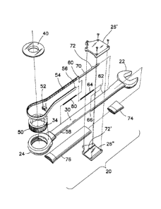
The ratchet gear 50 encircling the hexagonal socket 34 is illustrated in
FIG. 4. This ratchet gear 50 is mounted inside the box end 24 of the
preferred socket wrench 20 by way of a snap ring (not shown) for
example. A movable pawl 52 is also mounted inside the cavity of the
box end 24, as it is customary with ratchet wrenches.
A toothed belt 54, is mounted around the ratchet gear 50. Both ends of
the belt 54 extend along the shank 30 of the wrench 20. The shank 30
of the wrench 20 has spring seats that have been milled away, one on
each side of the shank 30. The return end 56 of the toothed belt 54
extends along a first spring seat 58. The driven end 60 of the toothed
belt 54 extends along a second spring seat 62. For reference purposes,
the first spring seat 58 is referred to as the return side spring seat 58, and
the second spring seat 62 is referred to as the driven side spring seat 62.
The spring seats 58 and 62 also designate the return side and the driven
side of the wrench 20.
A return spring 64 has one end thereof attached to the return end 56 of
the toothed belt 54, and a second end connected to a first anchor hook 66
at the far end of the return side spring seat 58 as can be seen in FIGS. 5
and 6. This return spring 64 is an extension type spring. This return
spring 64 is used to pull back on the toothed belt 54 during a return cycle
of the belt 54, when the slider body 26 is released.
The driven end 60 of the toothed belt 54 is attached to a sliding bar 70,
which slides back and forth frictionless along the driven spring seat 62.
The sliding bar 70 is linked to the slider body 26 by means of a dovetail
engagement as can be seen at labels 72 and 72' in FIGS. 4 and 5.
CA 02973605 2017-07-12
WO 2016/112453
PCT/CA2015/000609
The slider body 26 is made of two halves 26', 26", which enclose the
shank 30 of the preferred wrench in a sliding fit mounting. The
movement "A" of the slider body 26 along the guide segment 28 is
limited by the collars of a first 74 and second 76 sleeves mounted over
the shank 30 of the preferred wrench 20. The movement "A" is about 1
inch to 1-1/4 inch. This distance "A" is equivalent to a comfortable
movement of a user's thumb. Both sleeves 74, 76 are made of a
rubberized plastic material, offering a comfortable grip on the preferred
wrench 20.
Referring to FIG. 5, the ratchet gear 50 is movable in a clockwise
direction and is blocked by the pawl 52 in the counterclockwise
direction.
In the preferred ratchet wrench 20 with fine socket-indexing mechanism,
there is provided a second spring 80 mounted along the driven side
spring seat 62, between the slider bar 70 and the shank 30 of the wrench.
This second spring 80 prevents the occurrence of the effect of the
capstan equation as mentioned before. This second spring 80 is referred
to as the return-assist spring 80. This return-assist spring 80 has one
end connected to the attachment point 82 of the driven end 60 of the belt
54 to the slider bar 70 as it can be better seen in FIG. 7. The other end
of the return-assist spring 80 is attached to a second anchor hook 84
protruding from the shank 30 of the wrench along the driven side spring
seat 62, as illustrated in FIG. 8. The return-assist spring 80 is an
extension spring. The return-assist spring 80 and the return spring 64
have same physical and elastic properties.
Referring back to FIG. 5, the principle of operation of both springs 64,
80 will be explained. The portion of the ratchet gear 50 which is in
11
CA 02973605 2017-07-12
WO 2016/112453
PCT/CA2015/000609
contact with the toothed belt 54 can be divided into three segments "B",
"C" and "D". The first segment "B" is on the return side of the ratchet
gear 50. The second segment "C" is on the crest portion of the ratchet
gear 50, and the last segment "D" is on the driven side of the gear 50.
The return spring 64 applies a tension force along the belt 54 along the
first segment "B". The spring 80 applies a same compression force on
the belt along the third segment "D". Both forces are oriented opposite
from each other relative to the ratchet gear 50. Because both springs 64,
80 have same physical and elastic properties and a same elongation in
use, there is substantially no surface pressure between the belt 54 and the
crest segment "C" of the ratchet gear 50.
Although both springs 64, 80 work against each other relative to the
ratchet gear 50, both springs 64, 80 contribute to apply forces in a same
direction on the slider body 26, during both the driven movement and
the return movement of the belt. Both springs 64, 80 apply forces in a
same direction along the belt 54.
When the thumb knob 32 is pulled away from the box end 24 of the
preferred wrench 20, the movement of the slider body 26 creates an
unbalance between the springs 64 and 80 and causes the belt 54 to
engage with the crest "C" and the driven "D" segments of the ratchet
gear 50. A movement of the thumb knob 32 away from the ratchet gear
causes the belt 54 to engage with all three segments "B", "C" and "D"
of the ratchet gear 50, to turn the ratchet gear in a clockwise direction.
When the thumb knob 32 is released, the return-assist spring 80
counteracts the tension force of the return spring 64, relative to the
ratchet gear 50 causing the belt 54 to relax along the driven segment
12
CA 02973605 2017-07-12
WO 2016/112453
PCT/CA2015/000609
"D" and the crest segment "C" of the ratchet gear 50. Because the
slider bar 70 slides along the wrench in a frictionless manner, the return-
assist spring 80 pushes the belt 54 backward to force it to disengage
from the ratchet gear 50 and to slide against the outside surface of the
cavity in the box end 24 of the preferred wrench 20 as is illustrated in
FIG. 9. The teeth 90 of the ratchet gear have inclined surfaces facing
the driven end of the wrench. The teeth 92 on the belt 54 have inclined
surfaces facing the opposite direction. The teeth 90 of the ratchet gear
50 and the teeth 92 on the belt 54 cooperate with the action of the return-
assist spring 80 to push the belt 54 away from the segments "D" and
"C" of the ratchet gear 50.
The inside cavity of the box end 24 includes sufficient space to
accommodate the ratchet gear 50, the toothed belt 54 and a clearance
"E" between the tips of the teeth of the belt 54 and the tips of the teeth
of the ratchet gear 50. As a result, the toothed belt 54 can slide over the
ratchet gear 50 during the return cycle, without touching the gear 50, as
shown by the clearance "E" in FIG. 9.
The return spring 64 causes the belt 54 to slide easily over the return
segment "B" of the ratchet gear 50. Because of the return-assist spring
80 basically, the capstan equation principle does not impede the
operation of the preferred wrench 20. As a result, the operation of the
preferred wrench is smooth, consistent and positive, without any sign of
sticking or hesitation in its movement.
While one embodiment of the present invention has been illustrated in
the accompanying drawings and described herein above, it will be
appreciated by those skilled in the art that various modifications,
alternate constructions and equivalents may be employed. Therefore,
13
CA 02973605 2017-07-12
WO 2016/112453
PCT/CA2015/000609
the above description and illustrations should not be construed as
limiting the scope of the invention, which is defined in the appended
claims.
10
,
=
25
14