Note: Descriptions are shown in the official language in which they were submitted.
CA 02973814 2017-07-13
WO 2016/116841
PCT/1B2016/050192
1
TITLE: Guidance system of a drone
Field of application
The present invention relates to a guidance system for a drone.
In particular the present invention relates to a system of the
aforementioned type for automating the flight of a drone in an urban,
extra-urban or private environment.
The invention also relates to a method for guiding a drone and to a
drone intended to be guided by the aforementioned system.
Prior art
As is known, a drone or RPV (Remotely Piloted Vehicle) is a pilotless
remotely controlled aircraft, for example used for recognition and
surveillance operations.
Guiding of the drone is at present performed by means of a remote
control device.
In view of the recent commercial interest in drone, applications have
also been developed for smartphones or tablets which are easy to
operate and intuitive. These applications are based on a control
software which have performance features limited by the CPUs of the
smartphone or tablet, but are in any case able to analyze the data of
numerous sensors, such as accelerometers, gyroscopes,
magnetometers, etc., and manage in real time all the motors of the
drone, thus allowing a stable flight to be maintained and any
disturbances of the flying position to be compensated for.
The aforementioned remote control devices and applications may be
used with good results for HD-quality overhead photography or for
games, but the development of proper automated applications for the
drone, such as the delivery of merchandise or the video monitoring of
certain areas, is hindered by a number of factors, first and foremost the
need to automate flying of the drone, allowing flying to be performed
CA 02973814 2017-07-13
Printed: 11-04-2017 PESCPAMD = PCT/IB
2016/050 192
PCT/IB 2016/ov i - ub.u6.zul7
- 2 -
. =
=
independently of human control and outside of human visual range.
Some drones of the professional type are provided with an automatic
piloting system which is very closely related to those used by airlines -
and therefore has a certain complexity and cost. The system allows the
storage on-board the drone of a route by means of GPS positions.
However, it is still affected by problems which prevent the use of drones
in practical applications. For example, programming of this piloting ,
system for automating the flight of the drone in an urban- environment
requires the detection of a plurality of GPS coordinates in loco and the
storage of these coordinates in the drone memory, something which
requires time and also involves other safety-related problems, including
the need, to check for possible collisions with drones programmed with
their own pilot system or the absence of a ground reference point, to be
used in the event of recovery of the drone.
Moreover, the absence of or limited availability. of GPS connectivity in
some zones and the insufficient precision thereof do not allow the
known system to be used in an urban environment where further
obstacles hindering flight are present, such as tall movable machinery,
for example cranes, or where new buildings may appear in a relatively .
short amount of time, forming sudden obstacles which hinder flight. In
view of these problems it is almost impossible to comply with certain
= local, regional or national regulations, such as the prohibition of
flights
over a public meeting or the need to ensure a connectivity which is
always seo-ure and reliable.
All these problems in any case result in the need for the known .
automatic piloting systems to be accompanied by operator control. The
life of the drone batteries is a major limitation, since it requires manual
action to carry out replacement or perform recharging, this being a
further impediment to the real automation of the applications in the.
field or over long distances. US2014/032034 is an example of a
guidance system for a drone, according to the prior art.
The technical problem forming the basis of the present invention iS to
devise a guidance system for a drone which is able to improve
=
=
. .
PAR006BWO
=1/1 AMENDED SHEET
;
CA 02973814 2017-07-13
WO 2016/116841
PCT/1B2016/050192
3
automation and safety of flying, allowing the use of drones to be
extended to a wide range of applications in an urban, extra-urban or
private environment, substantially overcoming the drawbacks which
currently affect the known systems.
Brief description of the drawings
Figure 1 shows in schematic form a guidance system for a drone
according to the present invention.
Figure 2 shows an enlarged view of a portion of the guidance system for
=
a drone according to Figure 1.
Summary of the ihvention
The idea underlying the present invention is to fix a plurality of
electronic devices on a plurality of structural elements fixed to the
ground along a pre-existing land communication network, for example
an urban or extra-urban roadway or railway network, and to configure
some of the electronic devices so as to emit flight commands for a
drone, essentially by transmitting to the drone flight instructions from a
device, at a predefined altitude above the structural elements and along
the pre-existing communication network. The structural elements are
associated with a pre-existing electric power grid, for example they are
the lamp posts of a roadway network or the pylons of a railway line and,
advantageously, the devices are powered by the same electric grid
associated with the structural elements.
In particular, the devices are connected in a wireless network, for
example in a Mesh network, by means of which they form a virtual
aerial communication network for the drone. The virtual aerial
communication network corresponds to all the possible radio
connections between the devices. The flight path of the drone is
obtained from the configuration of a predetermined path chosen from
among all the possible paths along the virtual aerial communication
network. The path is formed by a plurality of nodes, corresponding to
the devices configured for the flight path, and sections situated between
CA 02973814 2017-07-13
WO 2016/116841
PCT/1B2016/050192
4
one node and the following one. The instructions for flight of the drone
from one node to the following one .are sent from the device fixed to the
structural element.
On the basis of the present idea, the technical problem is solved by a
guidance system for a drone, comprising:
- a plurality of structural elements, fixed to the ground and associated
with a private or pubic electric power grid, preferably poles;
- a plurality of devices fixed to the poles and powered by the same
electric power grid associated with the poles, the devices being
connected together in a wireless network and comprising a radio
communication module for communicating with the drone;
- a controller connected to the wireless network and intended to
program a flight path P of the drone between two or more poles,
preferably at a predefined flying altitude above the poles, by
transmitting configuration commands to the devices fixed to said two or
more poles, for configuring the radio communication modules, wherein
the radio communication module of one pole in the flight path is
configured to guide the drone towards the radio communication module
of a following pole in the flight path.
In one embodiment of the invention, the poles are for example the
pylons of a railway network and the power grid is branched off from the
electric railway network. In another embodiment, the poles are public
lamp posts of a roadway communication network.
The wireless network is preferably a Mesh network. For example, the
wireless network is a pre-existing Smartgrid used for regulating the
illumination of lamp posts in an urban environment.
The radio communication modules are configured to guide the drone
along the flight path P and form a second wireless network. The second
wireless network may have characteristics different from the first
wireless network. For example, according to one aspect of the invention,
the latency of the two networks is different or, according to another
CA 02973814 2017-07-13
WO 2016/116841
PCT/1B2016/050192
aspect of the invention, the second network may have a bandwidth
wider than the bandwidth of the first wireless network.
The device is therefore provided with two different radio interfaces, a
first interface operating on the first wireless network and a second
interface operating on the second network.
The second wireless network forms a control and monitoring network
since it is adapted to send to the drone information for piloting it along
the flight path and to receive information acquired from the drone; this
information is transferred from the second wireless network to the first
wireless network and, via the latter, to the various devices for
monitoring purposes.
At least one of the devices fixed to the pole comprises a landing base for
the drone and preferably also comprises an Ethernet interface of the
wireless or wired type which can be connected to the drone, in order to
transfer data from or to the drone. Moreover, preferably, at least one of
the devices provided with a landing base comprises means for
recharging or replacing a battery of the drone. Advantageously, said
means allow the autonomy of the drone to be prolonged so as to cover
many long flights using the same drone, without any human action.
Again according to the present invention, several devices provided with
a landing base form a third network, for example of the wireless type,
having a bandwidth greater than the bandwidth of the first wireless
network and intended for the transmission of data. In this case, the
device is therefore provided with a third wireless interface operating on
the third wireless network. In another variation of embodiment, the
devices provided with a landing base are connected in a network based
on a technology different from the aforementioned wireless networks,
such as optical fibre or Ethernet over copper or PLC technology.
It is also envisaged programming the devices so as to guide the drone to
the ground or cause it take off from the ground, at a given pole.
Preferably the flying altitude is therefore reached by causing the drone
to take off vertically and parallel to a pole, its descent onto the ground
CA 02973814 2017-07-13
WO 2016/116841
PCT/1B2016/050192
6
also being performed in this way.
According to a variation of embodiment landing is performed by means
of a system for allowing the drone to descend to the ground from a
landing base, comprising means for engaging the drone and means for
performing' sliding from the landing base down to the ground or to a
predetermined height, within human reach. Advantageously, the
descent system may also be programmed and automated, thus
simplifying also the drone landing operation, envisaged for example for
maintenance purposes. Moreover, the drone may be raised from the
ground as far as the landing base by means of the aforementioned
system, so as to take off directly from the base and not from the ground.
The system according to the present invention comprises optionally a
cable network between the poles, the cables being intended to be
engaged by the drone, for instance in case of breakdown during flight.
The cable network may be provided with an interface for acquisition
and/or transfer of data from/to the drone.
Furthermore, a physical safety network, which is preferably elastic, is
extended between the poles underneath a flight altitude of the drone
and is intended to catch the drone in the event of it falling to the
ground.
According to one aspect of the present invention and as more
specifically indicated in the description below, the programming of the
flight path in the controller comprises the configuration of one or more
timed stops of the drone, at a pole, to avoid collision with other drones.
The technical problem according to the present invention is also solved
by a drone intended to be guided by the aforementioned system and by
a corresponding piloting method, as claimed.
Further characteristic features and advantages of the present invention
will become clear from the description below provided solely by way of
example with reference to the attached drawings.
Detailed description
CA 02973814 2017-07-13
WO 2016/116841
PCT/1B2016/050192
7
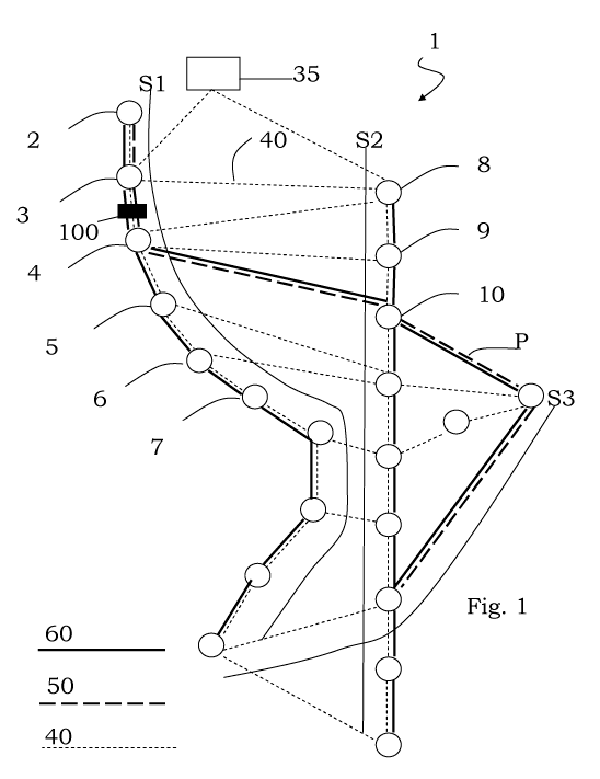
With reference to Figure 1 this shows in schematic form a guidance
system according to the present invention, denoted overall by the
reference number 1, and comprising a plurality of elements fixed to the
ground, for example poles 2-10 consisting of lamp posts situated along
a roadway network or pylons of a railway line.
Without limiting the scope of protection of the invention, the diagram
shown in Figure 1 relates in particular to a roadway network,
comprising n (three) roads S1-S3, with any intersections, for example
the intersection between the road S2 and S3. The poles are associated
with an electric power line intended, for example, to power the lighting
unit of the lamp post and branched off from of a per se pre-existing
urban power grid.
Some of the poles 2-4, 10 in Figure 1 are shown on a larger scale in
Figure 2, which also shows in schematic form, for each pole, an
electrical device 12-14, 20 which is fixed at the top end of the pole and
provided with a radio communication interface for communication in a
first wireless network. All the devices 12-20 are provided with such a
radio interface.
The latter has a predetermined coverage range which allows the device
12-20 to communicate with several other devices 12-20 within its
radius of action and to form, with all the devices 12-20 fixed to the
poles, the first wireless network denoted by the reference number 40 in
Figure 1 and indicated by a first broken line.
The wireless network 40 forms a virtual aerial communication network
which comprises all the possible paths which may be configured as
flight paths Pi.
In this connection, for configuration of a specific flight path P, a control
device, i.e. controller 35, is provided, said controller being connected to
=the wireless network and intended to transmit programming commands
to the devices 12-20. For example, in the diagram shown in Figure 1,
the controller 35 has configured a flight path P after transmitting
programming commands to the devices 12, 13, 14, 20.
CA 02973814 2017-07-13
WO 2016/116841
PCT/1B2016/050192
8
By way of example, these commands may comprise a code for
identifying the drone to be guided and, for each of the devices 12, 13,
14, a code identifying a following device 13, 14, 20 along the flight path
P, towards which drone may be guided, and/or the flight coordinates,
along with any deviation intervals.
Advantageously, according to an aspect of the present invention, the
first wireless network 40 may be a pre-existing urban Smartgrid, i.e.
already implemented and operative, for example for regulating the
lighting of the lamp posts along the roadway network.
The programming commands received by the device 12, 13, 14, 20 via
the first wireless network 40 are processed in the same device so as to
program a radio communication module 22, 23, ,24, 30 for
communicating with the drone.
In the figures, the drone is indicated by 100, being shown along a
section of its flight path between two lamp posts 3, 4, preferably at a
predefined height above the lamp posts. Along this section, the drone
100 has already received the flight commands from the device 13 and is
directed towards the device 14 where it will receive the flight commands
for the following section 4-5 of the flight path P,. i.e. for displacement
from pole 4 to pole 5.
Preferably, the devices involved in the flight path P form a second
wireless network, denoted in Figure 2 by 50 and indicated by a second
type of broken line, substantially corresponding to the flight path
already indicated by P in Figure 1. Some devices, for example the
device 12, 14 in Figure 2, are designed to allow landing of the drone 100
for various purposes, such as recharging of the drone battery or
replacement thereof with a battery available in the vicinity of the pole.
Advantageously, a discharged battery deposited by a drone in the
vicinity of a pole is recharged by means of the power grid associated
with the pole and then made available for other drones.
Landing of a drone on one of the devices 12, 14 provided with a base is
also envisaged for other functions, such as transfer of the data stored in
CA 02973814 2017-07-13
WO 2016/116841
PCT/1B2016/050192
9
the drone 100 to the device 12, 14 or, vice versa, transfer of the data
from the device 12, 14 to the drone 100, or for performing timed stops
of the drone 100 at the pole 2, 4, programmed by the controller 35 or
the devices 12-20. The stops have the function of regulating the traffic
of several drones 100, basically providing a traffic light system for
drones.
This system is for example installed as an ad hoc device in the wireless
network or in the vicinity of one of the devices 12-20 already present
and is necessary especially at possible intersections between the flight
paths programmed by the controller.
Moreover, landing of a drone on a base is envisaged for exchanging
transported merchandise between drones, namely for depositing
merchandise transported by a first drone and for acquisition of said
merchandise by a second drone which arrives after the first drone on
the landing base.
In this connection, the guidance system according to the present
invention also envisages programming the transportation of
merchandise or information by means of relaying between drones. For
example, with reference to Figure 2, in order to carry out a part of the
relaying operation from a starting point on a flight path (pole 2) to a
following point or terminal (pole 44), it is possible to guide a first drone
100 from the pole 2 to an intermediate pole 4 along the flight path P,
provided with landing base, and program unloading of the merchandise
at the intermediate pole 4. At the pole 4, a second drone (not shown in
the figures) may be programmed to acquire merchandise and transport
it the next pole 44 also provided with a landing base, where exchange
with a further drone or the definitive delivery of the .merchandise is
performed (if the pole 44 is the end pole along the flight path P).
Preferably, the devices provided with landing base also comprise an
Ethernet interface of the wireless or wired type intended for fast transfer
of data from/to the drone 100.
According to another aspect of the present invention, the devices
CA 02973814 2017-07-13
WO 2016/116841
PCT/1B2016/050192
provided with landing base form a third network, indicated by 70 in
Figure 2, having a bandwidth greater than the first wireless network 40
and the second wireless network 50 and intended to transfer the data
acquired from the drones (handover).
It should merely be pointed out that the third wireless network 70 and
the second wireless network 40 are shown separately, respectively, in
Figures 2 and 1, only for the sake of clarity thereof, but the second and
third networks may be simultaneously implemented and operative in
the guidance system 1, together with the network 50.
As an optional addition a cable network is provided, indicated by 60 in
Figure 1, said network being used to receive the drone 100 if it is
unable to reach the landing base or complete an aerial section between
two poles. According to one aspect of the invention, the cable network
60 may be used also for data transfer.
Furthermore, a protection network (not shown) is extended between the
poles, at an altitude lower than the flight altitude of the drone 100, for
catching the drone in the event of it suddenly breaking down and falling
to the ground. Advantageously the protection network may be used to
resolve other safety issues, for example by providing a protection system
for anyone passing underneath the lamp posts or travelling along the
roadway network and also preventing any damage to the drone in the
event of impact with the ground.