Language selection

Search

Patent 2973820 Summary

Third-party information liability

Some of the information on this Web page has been provided by external sources. The Government of Canada is not responsible for the accuracy, reliability or currency of the information supplied by external sources. Users wishing to rely upon this information should consult directly with the source of the information. Content provided by external sources is not subject to official languages, privacy and accessibility requirements.

Claims and Abstract availability

Any discrepancies in the text and image of the Claims and Abstract are due to differing posting times. Text of the Claims and Abstract are posted:

  • At the time the application is open to public inspection;
  • At the time of issue of the patent (grant).
(12) Patent Application: (11) CA 2973820
(54) English Title: FALL ARREST HARNESS
(54) French Title: HARNAIS ANTICHUTE
Status: Allowed
Bibliographic Data
(51) International Patent Classification (IPC):
  • A62B 35/00 (2006.01)
(72) Inventors :
  • BOOTHBY, STEPHEN (United States of America)
  • FLACHMAN, JOSEPH (United States of America)
(73) Owners :
  • WERNER CO. (United States of America)
(71) Applicants :
  • CMC RESCUE, INC. (United States of America)
(74) Agent: FASKEN MARTINEAU DUMOULIN LLP
(74) Associate agent:
(45) Issued:
(86) PCT Filing Date: 2016-01-06
(87) Open to Public Inspection: 2016-07-21
Examination requested: 2020-12-15
Availability of licence: N/A
(25) Language of filing: English

Patent Cooperation Treaty (PCT): Yes
(86) PCT Filing Number: PCT/US2016/012385
(87) International Publication Number: WO2016/114962
(85) National Entry: 2017-07-13

(30) Application Priority Data:
Application No. Country/Territory Date
62/104,016 United States of America 2015-01-15
14/986,285 United States of America 2015-12-31

Abstracts

English Abstract

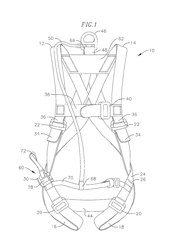
A fall arrest harness having a primary arrest attachment attached to a dorsal portion of a harness by a dorsal release strap, a releasable friction device positioned at a hip location of the harness and a repositioning tether releasably connected to the primary fall arrest attachment. The harness provides manual and controllable transfer of a suspension point from a dorsal location by letting out the dorsal release strap through the releasable friction device until tension from a user's weight is transferred from the dorsal release strap to the repositioning tether.


French Abstract

La présente invention concerne un harnais antichute comportant une fixation d'arrêt primaire fixée à une partie dorsale d'un harnais par une sangle de libération dorsale, un dispositif de frottement amovible positionné à un emplacement de hanche du harnais et une attache de repositionnement raccordée de façon amovible à la fixation antichute primaire. Le harnais permet un transfert manuel et contrôlable d'un point de suspension depuis un emplacement dorsal en laissant à l'extérieur la sangle de libération dorsale par l'intermédiaire du dispositif de frottement amovible jusqu'à ce que la tension du poids d'un utilisateur soit transférée de la sangle de libération dorsale à l'attache de repositionnement.

Claims

Note: Claims are shown in the official language in which they were submitted.


WHAT IS CLAIMED IS:

1. A fall arrest harness comprising:
a harness having a primary fall arrest attachment attached to a dorsal portion
of the
harness by a dorsal release strap;
a releasable friction device positioned on the dorsal release strap; and
a repositioning tether releasably connected to the primary fall arrest
attachment.
2. The harness of claim 1 further comprising:
a left shoulder section;
a right shoulder section;
a left leg section;
a right leg section; and
a chest section
3. The harness of claim 1 wherein the primary fall arrest attachment is a
rigid
attachment point.
4. The harness of claim 1 wherein the dorsal release strap extends from one
side
of the harness through the primary fall arrest attachment and then through the
releasable
friction device on an opposite side of the harness.
5. The harness of claim 4 wherein the releasable friction device is
positioned at a
hip location of the harness.
6. The harness of claim 1 wherein the releasable friction device includes a
strap
for manual manipulation of the releasable friction device.
7. The harness of claim 1 wherein the repositioning tether has an opposite
end
attached to a waist strap on the harness.
8. The harness of claim 1 wherein the repositioning tether has an opposite
end
attached to a chest strap on the harness.
9. A method of manually and controllably transferring a suspension point of
a
fall arrest harness from a dorsal location comprising the steps of:
initially arresting a fall of a user of the fall arrest harness at the dorsal
location; and
letting out a dorsal release strap through a releasable friction device until
tension from
a user's weight is transferred from the dorsal release strap to a
repositioning tether.

-4-


10. The method of claim 9 wherein the transfer of the suspension point
comprises
manipulating the releasable friction device to progressively reduce friction
on the dorsal
release strap thereby controlling transfer rate.
11. The method of claim 9 wherein the letting out of the dorsal release
strap is
without a tail of the dorsal release strap passing completely through the
second friction device
preventing any free and unrestricted movement of the dorsal release strap
thereby preventing
a secondary fall and arrest.
12. A fall arrest harness having shoulder and leg strapping;
a dorsal fall arrest attachment;
a dorsal release strap attached to the dorsal fall arrest attachment;
a repositioning tether releasably connected to the dorsal fall arrest
attachment; and
means for manually transferring the dorsal fall arrest attachment from a
dorsal
location to another location.
13. The harness of claim 12 wherein the means for manually transferring
includes
a releasable friction control device attached to the dorsal release strap.
14. The harness of claim 12 wherein the dorsal fall arrest attachment is a
rigid
attachment point.
15. The harness of claim 12 wherein the dorsal release strap extends from
one side
of the harness through the dorsal fall arrest attachment and then through the
releasable
friction control device on an opposite side of the harness.
16. The harness of claim 13 wherein the releasable friction control device
is
positioned at a hip location of the harness.
17. The harness of claim 12 wherein the dorsal release strap is positioned
by a
guide brace.
18. The harness of claim 12 wherein the releasable friction control device
includes
a strap for manually releasing the device.
19. The harness of claim 12 wherein the repositioning tether has an
opposite end
attached to a chest strap of the harness.

-5-

20. The
harness of claim 12 wherein the repositioning tether has an opposite end
attached to a waist strap of the harness.
-6-

Description

Note: Descriptions are shown in the official language in which they were submitted.


CA 02973820 2017-07-13
WO 2016/114962
PCT/US2016/012385
1 FALL ARREST HARNESS
BACKGROUND OF THE INVENTION
[0001] The invention relates generally to safety harnesses, and in
particular to harnesses
used for fall arrest. The current state of the art in fall arrest harnesses
utilizes a primary fall
arrest attachment point at the dorsal location. The dorsal location provides
for optimal
transfer of energy during the arrest of the falling person and is the required
location for the
primary fall arrest attachment point in several industry standards governing
the typical user of
a fall arrest harness.
[0002] A significant negative side effect of arresting a fall from the
dorsal location is the
difficulty of self-rescue. The inability to reach and manipulate a loaded
dorsal attachment
point necessitates rescue of the fallen worker by others. Any delay in rescue
can lead to
medical complications from the suspension from the dorsal location, which on
some
occasions has occurred in a manner of minutes depending on the worker and the
design of the
harness worn. The ability to transfer the suspension point from the dorsal
location to a more
advantageous location is therefore desirable. Previous designs have allowed
for either
automatic or manual transfer of the suspension point, but the transfer was not
controllable.
An automatic transfer can, depending on the deployment, result in arresting
the fall in an
undesirable location with potentially harmful energy transfer. A manual
transfer, if
uncontrolled, can result in a secondary fall and arrest with additional forces
to the body.
Consequently, a need exists for an improved fall arrest harness design that
addresses the
drawbacks of prior harnesses.
SUMMARY OF THE INVENTION
[0003] The present invention is directed to a fall arrest harness and
method of manually
and controllably transferring the suspension point from a dorsal location to a
more
advantageous location. This harness and method ensures an initial arrest at
the dorsal
location for optimal transfer of energy into the body, and a smooth transfer
of suspension
without a secondary fall and anest. The method may be one of several designs,
and may be
easily accessed and operated by the user of the harness. The harness comprises
left and right
shoulder sections, left and right leg sections, a chest section, buttocks
section and a dorsal
release strap. The harness further includes a repositioning tether which
connects a fall arrest
attachment point to a secondary location at the front of the harness.
[0004] A function of the present invention is to provide a
controllable means of
transferring the suspension point from the dorsal location to a more
advantageous location in
order to relieve the conditions leading to potential medical complications
until rescue of the
fallen person can be affected.
-1-

CA 02973820 2017-07-13
WO 2016/114962
PCT/US2016/012385
1 BRIEF DESCRIPTION OF THE DRAWINGS
100051 FIG. 1 is a front view of a fall arrest harness of the present
invention.
[00061 FIG. 2 is a rear view of the fall arrest harness of Fig. 1; and
[0007] FIG. 3 is a front view of an alternative embodiment fall arrest
harness of the
present invention.
DESCRIPTION OF THE PREFERRED EMBODIMENT
[0008] In FIGS. 1 and 2, one embodiment of a fall arrest harness 10 of
the present
invention is illustrated. The harness 10 is typically made from webbing, which
is a woven
fabric having multiple sections. Other materials can also be utilized. The
harness includes a
right shoulder section 12, a left shoulder section 14, each of the shoulder
sections extend over
the chest and abdomen of the wearer in the front and over the shoulder and
down the back of
the wearer in a crossing fashion and are stitched together 15. The harness
further includes'
webbing for a looped right leg section 16 and a left leg section 18. Each of
the leg sections
may pass through a friction device or buckle 20 positioned thereon. Each of
the leg sections
may, for example, have a segment 24 of strapping sewn by stitching 26 onto the
strapping to
form a loop through which the webbing passes to maintain the loop
configuration of the leg
sections, although other configurations are possible. An end 28 of the right
leg section is
looped through and connects to friction device 30. Ends 34 of the leg sections
loop through
and attach to buckles 22. Ends 36 of the shoulder sections also attach to
buckle 22.
[0009] The harness 10 further includes a chest section 38 which
extends through a buckle
40 for tightening the chest section around the wearer. The ends of the chest
section 38 are
sewn onto the shoulder section strapping. The harness further includes a sub-
pelvic strap 44
which is a segment of strapping sewn to each of the leg sections. The harness
further
includes a primary fall arrest attachment point 46 which is attached to the
harness 10 via a
dorsal release strap 48 and a repositioning tether 50. For example, attachment
point 46 may
be a D-ring.
[00101 In a first embodiment shown in Fig. 2 the dorsal release strap
48 is fixed at one
end 52 to the harness at the hip by being sewn 54 to the leg section. The
dorsal release strap
passes through the attachment point 46 at the dorsal location and then
downwardly through
the friction device 30 at an opposite hip location 60. The dorsal release
strap is retained in a
dorsal position by a guide webbing 62 and guide strap 64 sewn to guide webbing
62. The
dorsal release strap extends between the guide webbing 62 and guide strap 64.
[0011] The repositioning tether 50 is affixed to the attachment point
46 at one end 66 and
at an opposite end 68 to the front of the harness by either a waist strap 70
as shown in figure
1 or by being connected to chest strap 38 as shown in FIG. 3. A snap link or
other similar
connector (not shown) connects the harness to an appropriate anchorage via the
releasable
fall arrest attachment point 46.
-2-

CA 02973820 2017-07-13
WO 2016/114962
PCT/US2016/012385
1 10012] The dorsal release strap 48 has sufficient length (tail) to
allow the strap to be let
out through the friction device 30 until the tension from the user's weight
has been
transferred from the dorsal release strap to the repositioning tether 50 thus
preventing any
free and unrestricted movement of the dorsal release strap and thereby
preventing a
secondary fall and arrest.
100131 Transfer of the suspension point is accomplished by the user
manipulating the
friction device 30 at the hip location by pulling on strap 72. This location
provides the user
optimal leverage for manipulating the friction device, even if injured in the
initial fall. The
design of the friction device 30 allows the user to progressively reduce the
friction on the
dorsal release strap by pulling on strap 76 which disengages the friction
device thereby
controlling the rate at which the transfer is affected. Once the tension of
the user's weight
has been transferred to the repositioning tether 50, the user can manually
feed the remaining
tail of the dorsal release strap through the friction device. This allows a
full release of the
primary fall arrest attachment point 46 from the dorsal location of the
harness, completely
transferring the suspension of the user to the more advantageous location.
[0014] Although the present invention has been disclosed with respect
to embodiments
thereof, it is to be understood that changes and modifications can be made
therein which are
within the intended scope of the invention as hereinafter claimed.


-3-

Representative Drawing
A single figure which represents the drawing illustrating the invention.
Administrative Status

For a clearer understanding of the status of the application/patent presented on this page, the site Disclaimer , as well as the definitions for Patent , Administrative Status , Maintenance Fee  and Payment History  should be consulted.

Administrative Status

Title Date
Forecasted Issue Date Unavailable
(86) PCT Filing Date 2016-01-06
(87) PCT Publication Date 2016-07-21
(85) National Entry 2017-07-13
Examination Requested 2020-12-15

Abandonment History

There is no abandonment history.

Maintenance Fee

Last Payment of $210.51 was received on 2023-12-06


 Upcoming maintenance fee amounts

Description Date Amount
Next Payment if small entity fee 2025-01-06 $100.00
Next Payment if standard fee 2025-01-06 $277.00

Note : If the full payment has not been received on or before the date indicated, a further fee may be required which may be one of the following

  • the reinstatement fee;
  • the late payment fee; or
  • additional fee to reverse deemed expiry.

Patent fees are adjusted on the 1st of January every year. The amounts above are the current amounts if received by December 31 of the current year.
Please refer to the CIPO Patent Fees web page to see all current fee amounts.

Payment History

Fee Type Anniversary Year Due Date Amount Paid Paid Date
Application Fee $400.00 2017-07-13
Maintenance Fee - Application - New Act 2 2018-01-08 $100.00 2018-01-04
Maintenance Fee - Application - New Act 3 2019-01-07 $100.00 2018-12-18
Registration of a document - section 124 2020-06-01 $100.00 2020-06-01
Maintenance Fee - Application - New Act 4 2020-01-06 $100.00 2020-07-03
Late Fee for failure to pay Application Maintenance Fee 2020-07-03 $150.00 2020-07-03
Request for Examination 2021-01-06 $800.00 2020-12-15
Maintenance Fee - Application - New Act 5 2021-01-06 $200.00 2020-12-31
Maintenance Fee - Application - New Act 6 2022-01-06 $203.59 2022-01-04
Registration of a document - section 124 $100.00 2022-06-10
Maintenance Fee - Application - New Act 7 2023-01-06 $203.59 2022-12-23
Maintenance Fee - Application - New Act 8 2024-01-08 $210.51 2023-12-06
Owners on Record

Note: Records showing the ownership history in alphabetical order.

Current Owners on Record
WERNER CO.
Past Owners on Record
CLIMBTECH, LLC
CMC RESCUE, INC.
Past Owners that do not appear in the "Owners on Record" listing will appear in other documentation within the application.
Documents

To view selected files, please enter reCAPTCHA code :


To view images, click a link in the Document Description column. To download the documents, select one or more checkboxes in the first column and then click the "Download Selected in PDF format (Zip Archive)" or the "Download Selected as Single PDF" button.

List of published and non-published patent-specific documents on the CPD .

If you have any difficulty accessing content, you can call the Client Service Centre at 1-866-997-1936 or send them an e-mail at CIPO Client Service Centre.


Document
Description 
Date
(yyyy-mm-dd) 
Number of pages   Size of Image (KB) 
Request for Examination 2020-12-15 4 95
Maintenance Fee Payment 2020-12-31 1 33
Maintenance Fee Payment 2022-01-04 1 33
Examiner Requisition 2022-02-11 3 163
Amendment 2022-06-13 18 743
Claims 2022-06-13 4 181
Abstract 2017-07-13 1 62
Claims 2017-07-13 3 85
Drawings 2017-07-13 3 72
Description 2017-07-13 3 165
Representative Drawing 2017-07-13 1 25
Patent Cooperation Treaty (PCT) 2017-07-13 1 40
Patent Cooperation Treaty (PCT) 2017-07-13 1 56
International Search Report 2017-07-13 1 51
National Entry Request 2017-07-13 4 100
Cover Page 2017-09-12 2 45
Maintenance Fee Payment 2018-01-04 1 33
Maintenance Fee Payment 2018-12-18 1 33