Language selection

Search

Patent 2973859 Summary

Third-party information liability

Some of the information on this Web page has been provided by external sources. The Government of Canada is not responsible for the accuracy, reliability or currency of the information supplied by external sources. Users wishing to rely upon this information should consult directly with the source of the information. Content provided by external sources is not subject to official languages, privacy and accessibility requirements.

Claims and Abstract availability

Any discrepancies in the text and image of the Claims and Abstract are due to differing posting times. Text of the Claims and Abstract are posted:

  • At the time the application is open to public inspection;
  • At the time of issue of the patent (grant).
(12) Patent: (11) CA 2973859
(54) English Title: SPRAY BAR DEFLECTION TRAY
(54) French Title: PLATEAU DE DEVIATION DE RAMPE DE PULVERISATION
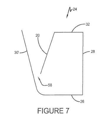
Status: Granted
Bibliographic Data
(51) International Patent Classification (IPC):
  • B65G 69/18 (2006.01)
  • B05B 12/36 (2018.01)
  • B05B 15/50 (2018.01)
(72) Inventors :
  • KEEFER, RONALD (United States of America)
(73) Owners :
  • MIDWEST INDUSTRIAL SUPPLY, INC. (United States of America)
(71) Applicants :
  • MIDWEST INDUSTRIAL SUPPLY, INC. (United States of America)
(74) Agent: SMART & BIGGAR LP
(74) Associate agent:
(45) Issued: 2018-10-09
(86) PCT Filing Date: 2016-01-12
(87) Open to Public Inspection: 2016-07-21
Examination requested: 2017-07-10
Availability of licence: N/A
(25) Language of filing: English

Patent Cooperation Treaty (PCT): Yes
(86) PCT Filing Number: PCT/US2016/013064
(87) International Publication Number: WO2016/115146
(85) National Entry: 2017-07-10

(30) Application Priority Data:
Application No. Country/Territory Date
62/102,336 United States of America 2015-01-12
62/164,848 United States of America 2015-05-21

Abstracts

English Abstract


A spray trough is described herein, includ-
ing a trough body, wherein the trough body has a bottom
portion, a first side portion, a second side portion, a front
portion, and a back portion, the bottom portion, the front
portion, and the back portion each having a first end and
a second end, a top plate having a first end and a second
end, wherein the first end of the top plate is fixedly at-
tached to the second end of the back portion, wherein the
top plate extends substantially perpendicular from the
second end of the back portion, and a deflector plate,
wherein the deflector plate is attached to the second end
of the front plate, wherein the deflector plate extends
downwardly from the second end of the front plate, such
that the deflector plate angles towards the front portion.


French Abstract

La présente invention concerne une auge de pulvérisation qui comprend un corps d'auge, le corps d'auge ayant une partie inférieure, une première partie latérale, une seconde partie latérale, une partie avant, et une partie arrière, la partie inférieure, la partie avant et la partie arrière ayant chacune une première extrémité et une seconde extrémité, une plaque supérieure ayant une première extrémité et une seconde extrémité, la première extrémité de la plaque supérieure étant fermement fixée à la seconde extrémité de la partie arrière, la plaque supérieure s'étendant sensiblement d'une manière perpendiculaire à partir de la seconde extrémité de la partie arrière, et une plaque de déviation, la plaque de déviation étant fixée à la seconde extrémité de la plaque avant, la plaque de déviation s'étendant vers le bas à partir de la seconde extrémité de la plaque avant, de telle sorte que la plaque de déviation s'incline vers la partie avant.

Claims

Note: Claims are shown in the official language in which they were submitted.

Claims:
1. A spray trough comprising:
a trough body, wherein the trough body has a bottom portion, a first side
portion, a second
side portion, a front portion, and a back portion, the bottom portion, the
front portion, and the back
portion each having a first end and a second end, wherein the first end of the
bottom portion is
directly connected to the first end of the front portion and the second end of
the bottom portion is
directly connected to the first end of the back portion;
a top plate having a first end and a second end, wherein the first end of the
top plate is fixedly
attached to the second end of the back portion, wherein the top plate extends
substantially
perpendicular from the second end of the back portion, wherein the second end
of the top plate does
not extend to the second end of the front portion, wherein the entire top
plate is substantially
perpendicular to the back portion; and,
a deflector plate, wherein the deflector plate is attached to the second end
of the top plate,
wherein the deflector plate extends downwardly from the second end of the top
plate, such that the
deflector plate angles towards the front portion.
2. The spray trough of claim 1, wherein the spray trough further comprises:

a drain, wherein the drain is located on either the first side portion or the
second side portion.
3. The spray trough of claim 1, wherein the front portion is substantially
perpendicular to the bottom portion.
4. The spray trough of claim 1, wherein the front portion extends outwardly
at an
angle from the bottom portion.
5. The spray trough of claim 1, wherein the deflector plate has an angle of

between about 15 degrees and about 70 degrees.
6. The spray trough of claim 5, wherein the deflector plate has an angle of

between about 30 degrees and about 60 degrees.
7. The spray trough of claim 6, wherein the deflector plate has an angle of
about
45 degrees.
8. The spray trough of claim 1, wherein the trough further comprises:
a flange, wherein the flange is connected to the second end of the top plate
and extends
perpendicularly downward from the second end of the top plate, wherein the
deflector plate has a first
6

portion, a second portion, and a third portion, wherein the first portion is
attached to and parallel with
the top plate, the second portion is attached to and parallel with the flange,
and the third portion is
angled away from the flange and the top plate toward the front portion.
9. The spray trough of claim 2, wherein the bottom portion is sloped toward
the
drain.
10. The spray trough of claim 9, wherein the bottom portion is sloped at
least one
eighth of an inch per foot.
11 . The spray trough of claim 1, wherein the spray trough is
configured to receive
downward spray from an associated nozzle located above the spray trough.
7

Description

Note: Descriptions are shown in the official language in which they were submitted.


CA 02973859 2017-07-10
SPRAY BAR DEFLECTION TRAY
Background
A. Field
[0001] This application claims priority to U.S. Serial No. 62/102,336, filed
January
12, 2015 and U.S. Serial No. 62/164,848, filed May 21, 2015. This invention
generally relates to methods and apparatuses for dust suppression for railroad
cars,
and more particularly to a deflection tray for a spray bar.
B. Description of the Related Art
[0002] Currently, the contents of rail cars are sprayed from straight arms.
Spray bars
are typically attached to a trim chute via a permanent bracket. The spray from
the
nozzles creates spray and foam when sprayed into a trough, when not in use.
II. Summary
[0003] The present teaching provides a deflection tray for a spray bar for
more
efficiently spraying contents of rail cars, and for reducing waste and foaming
during
application.
[0004] Other benefits and advantages will become apparent to those skilled in
the art
to which it pertains upon reading and understanding of the following detailed
specification.
III.Brief Description of the Drawings
[0005] Example arrangements are described hereinafter with reference to the
accompanying drawings.
[0006] FIGURE 1 shows a side view of the spray bar;
10007] FIGURE 2 shows a front and side view of the spray bar, as well as the
frame;
10008] FIGURE 3 shows a perspective view of a spray nozzle and the deflection
tray;
[0009] FIGURE 4 shows several views of a diversion trough;
100101 FIGURE 5 shows several views of a stiffener in the diversion trough;
[0011] FIGURE 6 shows a cross-sectional view of the trough with a deflector;
and,
[0012] FIGURE 7 shows a cross-sectional view of the trough.
1

CA 02973859 2017-07-10
IV. Detailed Description
[0013] In reference to the FIGURES, the spray bar 60 has a profile to
substantially
match the profile of the contents of a railroad car. For example, the railroad
car could
be carrying coal 12, which needs to be treated so that as little coal dust
leaves the
railroad car during travel as possible. The spray bar 60 is curved to
substantially
match the coal profile 12. The spray bar 60 is contained in a housing, and the

housing is connected to the trim/profile chute 14 at the silo. With continuing

reference to the FIGURES, the spray bar 60 has a straight bar 14, which in one

embodiment is made of metal, with an inlet side, quick change brackets (shown,
but
not referenced) for attachment and removal from the trim chute 14, and
connectors
(shown, but not referenced) for attachment to the hose (shown, but not
referenced).
100141 With continuing reference to the FIGURES, the spray bar 60 has at least
one
valve (shown, but not referenced) connected to the straight bar 14 via hoses
(shown,
but not referenced). In one embodiment, the valves (shown, but not referenced)
are
pneumatic valves, controlled by air pressure, with no use of electricity.
Attached to
the valves arc nozzles 10 for distribution of the chemical. The pneumatic
valves
allow for precise control of flow, which can be adjustable, and helps prevent
dripping.
The valves have intake openings and exhaust openings to be controlled by air
pressure. The openings are connected with a T-pipe and hose to a pressurized
air
source. The housing in which the spray bar 60 is contained, in one embodiment,
is
made of polypropylene for ease of cleaning and for being light weight.
[0015] With continuing reference to the FIGURES, the components of the spray
bar
60, in one embodiment, are designed to be changed out quickly and efficiently.
Also,
in at least one embodiment, the housing has flexible extensions which allow
for
different sized railroad cars.
(0016] With continuing reference to the FIGURES, the spray bar 60 is mounted
to the
trim chute 14 via a frame 16 as shown in FIGURE 2. In one embodiment, the
frame
16 is a lightweight aluminum frame. The frame 16 is fixedly attached to the
chute 14,
but the spray bar 60 is removably attached to the frame 16, so that the spray
bar 60
may be easily removed for maintenance and cleaning. The spray bar assembly is
contained within a housing, and the housing is removably attached to the frame
16.
2

CA 02973859 2017-07-10
The frame 16 allows for significant support while in operation, and the fact
that it is
removably attached allows for ease of removal, cleaning, and maintenance. With

reference now to FIGURE 3, a spray nozzle 10 is shown with a deflection tray
20.
The deflection tray 20 is placed beneath the opening 18 of the spray nozzle
10, so that
the chemical is deflected off of the tray 20 and in to the trough 24. The
deflection of
the spray 22 off of the deflection tray 20 reduces spray and waste, as well as
reduces
foaming of the chemical while the trough 24 is engaged. In one embodiment, the

deflection tray 20 is angled at substantially 45 degrees, but any angle that
allows for
the reduction of foaming can he used.
[0017] With reference to FIGURES 4-7, the trough 24 can fill with liquid and
foam,
where it can flow to one side where gravity feeds the liquid away. The trough
24 has
a front portion 30, a back portion 28, a bottom portion 25, a first side
portion 36, a
second side portion 38, a top plate 32, and a flange 34. The front portion 30
and back
portion 28 connect to the bottom portion 26, wherein the front and back
portions 30,
28 are substantially parallel to one another. The top plate 32 connects to the
back
portion as shown in FIGURE 4, and the flange 34 extends downwardly from the
top
plate 32, as shown in FIGURE 4. Since the nozzles 10 spray continuously, the
trough
24 is engaged to catch the spray 22 when no chemical needs to be applied. The
trough 24 catches the spray 22 to avoid having the spray 22 go directly on the
ground.
An issue with the spray 22 going into the trough 24 is that the spray tends to
splash
and foam when contacting the bottom portion 26. In one example, the trough 24
can
be twelve feet long, the spray is nine feet, which leaves approximately
eighteen
inches on each side of the trough 24. This space on either side provides space
for the
foam to gather, which can be held in the trough 24 by cover 40 as shown in
FIGURE
5. A top cover 40 and a vent insert 46 are provided, with the vent insert 46
being
deliberately vented to allow foam to enter, but not escape. In another
example, the
trough 24 can have a first cover 40 and a second cover 42, wherein the covers
40, 42
cover the approximately eighteen inches on each side of the trough 24. The
trough 24
can also have a first vent insert 40 and a second vent insert 42.
[0018] Another example provides varying degrees of tilt to the trough 24, so
that the
foam/liquid is evacuated more quickly, which reduces the amount of foam. The
3

CA 02973859 2017-07-10
trough 24 can be tilted toward a drain 44, which is connected to one of the
side
portions 36, 38. The greater the slope, the quicker the foam/liquid will be
evacuated
from the trough 24. In one example, the trough 24 is tilted toward the drain
44 at
least one eighth of an inch per foot. In another example, a collecting tray 50
is
provided below the trough 24 to collect any liquid that collects on the face
of the
trough 24 and drips down. In one embodiment, the tray 50 has an absorbent,
porous
material to collect liquid and allow evaporation.
[0019] With reference to FIGURE 6, deflector tray 20 is attached to the trough
24.
The deflector tray 20 has a first portion 52, which is attached to the top
plate 32, a
second portion 54, which is attached to the flange 34, and a third portion 56,
which
angles outwardly from the flange 34 toward the front portion 30. The deflector
tray
20 angles to create a funnel wherein the liquid is directed through a narrow
slit 58,
which decreases the foam created, and contains the foam. The deflector tray 20
can
be angled at between about 15 degrees to about 70 degrees (including, but not
limited
to 15, 16, 17, 18, 19, 20, 21, 22, 23, 24, 25, 26, 27, 28, 29, 30, 31, 32, 33,
34, 35, 36,
37, 38, 39, 40, 41, 42, 43, 44, 45, 45, 47. 48, 49, 50, 51, 52, 53, 54, 55,
56, 57, 58. 59,
60, 61, 62, 63, 64, 65, 66, 67, 68, 69, and 70), and within that range can be
between
about 30 degrees and about 60 degrees (including, but not limited to 30, 3 I.
32, 33,
34, 35, 36, 37, 38, 39, 40, 41, 42, 43, 44, 45, 45, 47, 48, 49, 50, 51, 52,
53, 54, 55, 56,
57, 58, 59, and 60), and within that range can be about 45 degrees. The
deflector tray
20 can be angled at greater than about 15 degrees, can be angled at less than
about 70
degrees, can be angled at greater than about 30 degrees, or can be angled at
less than
about 60 degrees.
[0020] With reference to FIGURE 7, in another example, the front portion 30'
of the
trough 24' is angled outwardly, so that it is closer to being perpendicular to
the
incoming spray 22, which allows for the cutting off of the spray 22 as it
moves into
and out of the trough 24. The tilted trough 24' embodiment can be incorporated
with
any of the above mentioned embodiments as well.
[0021] The embodiments have been described, hereinabove. It will be apparent
to
those skilled in the art that the above methods and apparatuses may
incorporate
changes and modifications without departing from the general scope of the
present
4

CA 02973859 2017-07-10
teaching. It is intended to include all such modifications and alterations
insofar as
they come within the scope thereof.

Representative Drawing
A single figure which represents the drawing illustrating the invention.
Administrative Status

For a clearer understanding of the status of the application/patent presented on this page, the site Disclaimer , as well as the definitions for Patent , Administrative Status , Maintenance Fee  and Payment History  should be consulted.

Administrative Status

Title Date
Forecasted Issue Date 2018-10-09
(86) PCT Filing Date 2016-01-12
(87) PCT Publication Date 2016-07-21
(85) National Entry 2017-07-10
Examination Requested 2017-07-10
(45) Issued 2018-10-09

Abandonment History

There is no abandonment history.

Maintenance Fee

Last Payment of $210.51 was received on 2023-10-13


 Upcoming maintenance fee amounts

Description Date Amount
Next Payment if small entity fee 2025-01-13 $100.00
Next Payment if standard fee 2025-01-13 $277.00

Note : If the full payment has not been received on or before the date indicated, a further fee may be required which may be one of the following

  • the reinstatement fee;
  • the late payment fee; or
  • additional fee to reverse deemed expiry.

Patent fees are adjusted on the 1st of January every year. The amounts above are the current amounts if received by December 31 of the current year.
Please refer to the CIPO Patent Fees web page to see all current fee amounts.

Payment History

Fee Type Anniversary Year Due Date Amount Paid Paid Date
Request for Examination $800.00 2017-07-10
Application Fee $400.00 2017-07-10
Maintenance Fee - Application - New Act 2 2018-01-12 $100.00 2017-07-10
Final Fee $300.00 2018-08-27
Maintenance Fee - Patent - New Act 3 2019-01-14 $100.00 2019-01-07
Maintenance Fee - Patent - New Act 4 2020-01-13 $100.00 2019-12-16
Maintenance Fee - Patent - New Act 5 2021-01-12 $200.00 2020-12-18
Maintenance Fee - Patent - New Act 6 2022-01-12 $204.00 2021-09-29
Maintenance Fee - Patent - New Act 7 2023-01-12 $203.59 2022-10-14
Maintenance Fee - Patent - New Act 8 2024-01-12 $210.51 2023-10-13
Owners on Record

Note: Records showing the ownership history in alphabetical order.

Current Owners on Record
MIDWEST INDUSTRIAL SUPPLY, INC.
Past Owners on Record
None
Past Owners that do not appear in the "Owners on Record" listing will appear in other documentation within the application.
Documents

To view selected files, please enter reCAPTCHA code :


To view images, click a link in the Document Description column. To download the documents, select one or more checkboxes in the first column and then click the "Download Selected in PDF format (Zip Archive)" or the "Download Selected as Single PDF" button.

List of published and non-published patent-specific documents on the CPD .

If you have any difficulty accessing content, you can call the Client Service Centre at 1-866-997-1936 or send them an e-mail at CIPO Client Service Centre.


Document
Description 
Date
(yyyy-mm-dd) 
Number of pages   Size of Image (KB) 
Abstract 2017-07-10 2 66
Claims 2017-07-10 3 106
Drawings 2017-07-10 6 167
Description 2017-07-10 7 317
Representative Drawing 2017-07-10 1 7
International Search Report 2017-07-10 4 148
National Entry Request 2017-07-10 6 139
Amendment / PPH Request / Amendment 2017-07-10 12 541
Description 2017-07-11 5 178
Claims 2017-07-11 2 49
Examiner Requisition 2017-08-04 5 287
Cover Page 2017-08-29 2 44
Amendment 2017-09-27 2 73
Amendment 2018-01-31 8 247
Claims 2018-01-31 2 64
Interview Record Registered (Action) 2018-03-08 1 15
Amendment 2018-03-01 6 179
Claims 2018-03-01 2 63
Final Fee 2018-08-27 1 47
Cover Page 2018-09-11 1 36