Note: Descriptions are shown in the official language in which they were submitted.
CA 02973955 2017-07-13
WO 2016/115451 PCT/US2016/013577
NANO-SIZED FUNCTIONAL BINDER
FIELD OF THE INVENTION
The present invention relates generally to the field of exhaust gas purifying
catalysts. More
particularly, the invention relates to catalytic articles having a washcoat on
a substrate, the
washcoat containing a catalyst component and a functional binder component.
BACKGROUND OF THE INVENTION
Catalytic converters treat exhaust gas streams of combustion engines to
convert, trap, and/or
adsorb undesirable components in order to meet stringent emissions standards.
Components used
in catalytic converters include, but are not limited to platinum group metals
(PGMs), base metals
(BMs), oxygen storage components (OSCs), and/or molecular sieves, such as
zeolites. Catalytic
converters are designed to meet the needs of specific applications, such as
exhaust streams of
diesel engines (e.g., Diesel Oxidation Catalysts (DOCs), Selective Catalytic
Reduction (SCR)
catalysts, and Catalyzed Soot Filters (CSF)) and exhaust streams of gasoline
engines (e.g., Three-
Way Conversion (TWC) catalysts).
Ceramic honeycombs are used in a variety of applications, including as
particulate filters
and flow-through substrates for reducing pollutants such as carbon monoxide
(CO), hydrocarbons
(HC), and nitrogen oxides (NO) in engine exhaust gas streams. In many of these
applications, a
washcoat material is applied to the honeycomb before it is used or further
processed, for example,
coating catalytic materials such as DOCs, SCR catalysts, and TWC catalysts
onto such
honeycombs. A washcoat generally, is a thin, adherent coating of a catalytic
or other material
applied to a substrate, such as a honeycomb-type carrier member. In some
processes, a
honeycomb substrate is first washcoated and the catalytic metals (for example,
platinum,
palladium, and/or rhodium) are applied to the washcoat after the washcoat has
been dried and
calcined. In other instances, the catalytic metals are deposited onto the
washcoat material and the
washcoat is then applied to the honeycomb. In either case, the washcoat fills
the pores of the
honeycomb substrate and reduces the porosity of the honeycomb substrate.
Thus, there is a need for a washcoat, e.g., for application to honeycomb
substrates, that can
be used with catalytic converters that is sufficiently porous to permit the
passage of the exhaust gas
stream being treated.
-1-
CA 02973955 2017-07-13
WO 2016/115451 PCT/US2016/013577
SUMMARY OF THE INVENTION
A first aspect of the invention pertains to a catalytic article for
purification of exhaust gases
of combustion engines. The compositions and articles disclosed herein have
broad applicability
and can be employed for a range of uses by tailoring the specific components
thereof to address
various components of exhaust gases, as will be described herein in further
detail.
In a first embodiment, a catalytic article for purification of exhaust gases
of combustion
engines comprises a substrate having a washcoat on the substrate, the washcoat
containing a
catalytic component having a first average (D50) particle size and a
functional binder component
having a second average (D50) particle size of about 10 nm to about 1000 nm,
wherein the ratio of
the first average (D50) particle size to the second average (D50) particle
size is greater than about
10:1.
In a second embodiment, the functional binder component of the catalytic
article of the first
embodiment has a structure selected from the group consisting of zeolite,
Perovskite, spinel,
composite, and combinations thereof.
In a third embodiment, the catalytic article of the functional binder
component of the first
and/or second embodiments comprises a transition metal oxide, a rare-earth
metal oxide, or a
combination thereof.
In a fourth embodiment, the transition metal oxide of the catalytic article of
the third
embodiment comprises an oxide selected from the group consisting of zirconium
oxide, copper
oxide, nickel oxide, iron oxide, manganese oxide, and combinations thereof.
In a fifth embodiment, the rare-earth metal oxide of the catalytic article of
the third
embodiment comprises an oxide selected from the group consisting of cerium
oxide, lanthanum
oxide, neodymium oxide, yttrium oxide, praseodymium oxide, and combinations
thereof.
In a sixth embodiment, the composite of the catalytic article of the second
embodiment
comprises a solid solution ceria/zirconia having the general formula
Ce05Zr0502.
In a seventh embodiment, the washcoat of the catalytic article of the first
through sixth
embodiments has a porosity of about 10% to about 50% as measured by scanning
electron
microscopy (SEM).
In an eighth embodiment, the washcoat of the catalytic article of the first
through seventh
embodiments has a porosity of about 20% to about 30% as measured by SEM.
In a ninth embodiment, the catalytic component of the catalytic article of the
first through
eighth embodiments comprises a particle size distribution of d10> about 1.0
nm, d50 = about 3
nm to about 5 nm, and d90 = about 9 nm to about 13 nm.
-2-
CA 02973955 2017-07-13
WO 2016/115451 PCT/US2016/013577
In a tenth embodiment, the catalytic component of the catalytic article of the
first through
ninth embodiments is selected from the group consisting of an SCR catalyst, a
TWC catalyst, a
diesel oxidation catalyst (DOC), and a catalyzed soot filter (CSF).
In an eleventh embodiment, the catalytic component of the catalytic article of
the first
through tenth embodiments comprises a high surface area metal oxide support
and a component
selected from the group consisting of a platinum group metal (PGM), a base
metal (BM), an
oxygen storage component (OSC), a molecular sieve, and combinations thereof.
In a twelfth embodiment, the high surface area metal oxide support of the
catalytic article of
the eleventh embodiment comprises alumina and the functional binder comprises
a ceria-
containing oxygen storage component (OSC), wherein the alumina to OSC ratio by
weight is
about 0.5 to about 10Ø
In a thirteenth embodiment, the functional binder component of the catalytic
article of the
first through twelfth embodiments is substantially free of platinum group
metal.
In a fourteenth embodiment, the substrate of the catalytic article of the
first through
thirteenth embodiments is a honeycomb substrate.
In a fifteenth embodiment, the honeycomb substrate of the catalytic article of
the fourteenth
embodiment comprises a wall flow filter.
In a sixteenth embodiment, the honeycomb substrate of the catalytic article of
the fourteenth
embodiment comprises a flow through substrate.
In a seventeenth embodiment, the functional binder component of the catalytic
article of the
first through sixteenth embodiments comprises about 0.5 wt.% to about 40 wt.%,
on a solids basis,
of the washcoat.
In an eighteenth embodiment, the functional binder component of the catalytic
article of the
first through seventeenth embodiments has a second average (D50) particle size
in the range of
about 10 nm to about 40 nm.
A second aspect of the present invention is directed to a method of purifying
exhaust gases.
In a nineteenth embodiment is provided a method of purifying exhaust gases
comprising
contacting the exhaust gases with the catalytic article of any of the first
through eighteenth
embodiments.
A third aspect of the present invention is directed to a method of preparing a
washcoat.
In a twentieth embodiment is provided a method of preparing a washcoat,
comprising
providing a first catalyst component, optionally milled, having a first
particle size distribution of
d10 > about 1.0 pm, d50 = about 3 pin to about 5 pm, and d90 = about 9 pin to
about 13 pm;
providing a second catalyst component, optionally milled, having a second
particle size
-3-
CA 02973955 2017-07-13
WO 2016/115451 PCT/US2016/013577
distribution of d10 > about 1.0 pm, d50 = about 3 pin to about 5 pm, and d90 =
about 9 pin to about
13 pm; mixing the first catalyst component and the second catalyst component
in an aqueous
solution to provide a catalytic component having a first average (D50)
particle size; and
combining the aqueous solution of the catalytic component with a functional
binder component to
provide a washcoat, wherein the functional binder component has a second
average (D50) particle
size of about 10 nm to about 1000 nm, wherein the ratio of the first average
(D50) particle size to
the second average (D50) particle size is greater than about 10:1.
In a twenty-first embodiment, the first catalyst component in the method of
the twentieth
embodiment comprises a high surface area metal oxide support.
In a twenty-second embodiment, the second catalyst component in the method of
the
twentieth and twenty-first embodiments comprises an oxygen storage component
(OSC).
In a twenty-third embodiment, the high surface area metal oxide support in the
method of
the twentieth through twenty-second embodiments comprises alumina.
In a twenty-fourth embodiment, the high surface area metal oxide support in
the method of
the twenty-second embodiment comprises alumina, and the ratio of alumina to
OSC is about 0.5 to
about 10Ø
BRIEF DESCRIPTION OF THE DRAWINGS
The disclosure may be more completely understood in consideration of the
following
detailed description of various embodiments of the disclosure in connection
with the
accompanying drawings, in which:
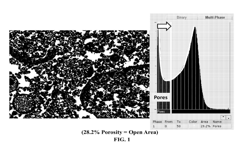
FIG. 1 is a scanning electron microscopy (SEM) image showing the porosity of a
sample
prepared according to one or more embodiments disclosed herein;
FIG. 2 is a perspective view of a honeycomb-type refractory carrier member
which may be
used in accordance with one or more embodiments disclosed herein;
FIG. 3 is a partial cross-sectional view enlarged relative to FIG. 1, which
shows an enlarged
view of one of the gas flow passages shown in FIG. 1;
FIG. 4A shows a perspective view of a wall flow filter substrate according to
one or more
embodiments;
FIG. 4B shows a cutaway view of a section of a wall flow filter substrate
according to one
or more embodiments;
FIG. 5 is a bar graph of emission results for catalytic articles prepared
according to the
Examples provided herein;
-4-
CA 02973955 2017-07-13
WO 2016/115451 PCT/US2016/013577
FIG. 6 is a bar graph of emission results for catalytic articles prepared
according to the
Examples provided herein;
FIG. 7 provides SEM images of catalytic articles prepared according to the
Examples
provided herein;
FIG. 8 is a bar graph of emission results for catalytic articles prepared
according to Example
2;
FIG. 9 is a bar graph of emission results for catalytic articles prepared
according to the
Examples provided herein;
FIG. 10 provides SEM images of catalytic articles prepared according to the
Examples
provided herein;
FIG. 11 provides SEM images of catalytic articles prepared according to the
Examples
provided herein;
FIG. 12 is a graph of size distribution by intensity for catalytic articles
prepared according
to the Examples provided herein;
FIG. 13 is a graph of size distribution by intensity for catalytic articles
prepared according
to the Examples provided herein;
FIG. 14 provides SEM images of a catalytic article and comparative catalytic
articles
prepared according to the examples provided herein;
FIG. 15 provides SEM images comparing densely packed catalyst material with
catalyst
material comprising a nano-functional binder as disclosed herein; and
FIG. 16 provides a model of porosity and impact on crack formation.
DETAILED DESCRIPTION OF THE PREFERRED EMBODIMENTS
Before describing several exemplary embodiments of the invention, it is to be
understood that
the invention is not limited to the details of construction or process steps
set forth in the following
description. The invention is capable of other embodiments and of being
practiced or being carried
out in various ways.
It has been found that a porous washcoat can be created by precisely
controlling the particle
size distribution of the components of the washcoat. Specifically, it has been
found that the use of a
functional binder component having nano-sized particles can provide a washcoat
that is porous and
virtually crack-free.
With respect to the terms used in this disclosure, the following definitions
are provided.
As used herein, the terms "catalyst" or "catalyst composition" or "catalyst
material" or
"catalyst component" refer to a material that promotes a reaction.
-5-
CA 02973955 2017-07-13
WO 2016/115451 PCT/US2016/013577
As used herein, the term "catalytic article" refers to an element that is used
to promote a
desired reaction. For example, a catalytic article may comprise one or more
washcoats containing
a catalytic species, e.g. a catalyst composition, on a substrate.
According to one or more embodiments, a catalytic article for purification of
exhaust gases of
combustion engines comprises a substrate having a washcoat on the substrate,
the washcoat
containing a catalytic component having a certain average (D50) particle size
and a functional binder
component having a certain average (D50) particle size, wherein the ratio of
such average (D50)
particle sizes is above a certain value or within a particular range (e.g.,
greater than about 10:1). For
example, in one embodiment, such a catalytic article is provided wherein the
catalytic component has
a first average (D50) particle size and the functional binder component has a
second average (D50)
particle size of about 10 nm to about 1000 nm. In one or more embodiments, the
ratio of the first
average (D50) particle size to the second average (D50) particle size in such
washcoats is greater than
about 10:1.
In one or more embodiments, the catalytic component and the functional binder
component are
applied to a substrate as a washcoat. As used herein, the term "substrate"
refers to a monolithic
material onto which the catalyst is placed, typically in the form of a
washcoat. A washcoat is
generally formed by preparing a slurry containing a specified solids content
(e.g., about 10% to
about 50% by weight or about 30% to about 40% by weight) of solid/catalyst
(here, including both
the catalytic component and the functional binder component) in a liquid
vehicle, which is then
coated onto a substrate and dried to provide a washcoat layer on the
substrate.
As used herein, the term "washcoat" has its usual meaning in the art of a
thin, adherent
coating of a catalytic or other material applied to a substrate material, such
as a honeycomb-type
carrier member, which is sufficiently porous to permit the passage of the gas
stream being treated.
Functional Binder Component
In one or more embodiments, the functional binder component has nano-sized
particles with
average (D50) particle size of about 10 nm to about 1000 nm, including about
10 nm, about 50
nm, about 100 nm, about 150 nm, about 200 nm, about 250 nm, about 300 nm,
about 350 nm,
about 400 nm, about 450 nm, about 500 nm, about 550 nm, about 600 nm, about
650 nm, about
700 nm, about 750 nm, about 800 nm, about 850 nm, about 900 nm, about 950 nm,
and less than
about 1000 nm. In specific embodiments, the functional binder component has
nano-size particles
with an average (D50) particle size of about 200 nm to about 400 nm, including
about 200 nm,
about 210 nm, about 220 nm, about 230 nm, about 240 nm, about 250 nm, about
260 nm, about
270 nm, about 280 nm, about 290 nm, about 300 nm, about 310 nm, about 320 nm,
about 330 nm,
about 340 nm, about 350 nm, about 360 nm, about 370 nm, about 380 nm, about
390 nm, and
-6-
CA 02973955 2017-07-13
WO 2016/115451 PCT/US2016/013577
about 400 nm. In specific embodiments, the functional binder component has
nano-sized particles
with an average (D50) particle size of about 10 nm to about 40 nm, including
about 10 nm, about
15 nm, about 20 nm, about 25 nm, about 30 nm, about 35 nm, and about 40 nm.
As will be described in greater herein below, relevant average (D50) particle
sizes of the
functional binder component can be related to the average particle size of the
component(s) with
which the binder component is combined (e.g., catalyst components).
Accordingly, beneficial
average (D50) particle sizes of the functional binder component can vary
widely, depending upon
the average (D50) particle size of the catalytic component to be associated
therewith. The
average (D50) particle sizes of functional binder components as disclosed
herein can be described
in terms of the ratio of average (D50) particle size of catalyst component(s)
to average (D50)
particle size of functional binder component. Such ratios are provided and
described in greater
detail herein below.
The average (D50) particle sizes of the functional binder component can be
measured using a
CILAS 1064 Laser Particle Size Analyzer according to the manufacturer's
recommended liquid mode
method with a measurement range of 0.04 to 500 microns. For particles <40 nm,
the average (D50)
particle size can be measured using a Malvern Zetasizer Nano ZS, which is a
high performance two
angle particle and molecular size analyzer for the enhanced detection of
aggregates and
measurement of small or dilute samples, and samples at very low or high
concentration using
dynamic light scattering with 'NIBS' optics.
In one or more embodiments, the washcoat comprises about 0.5 wt.% to about 40
wt.%, on
a solids basis, of the functional binder component, including about 0.5 wt.%,
about 1 wt.%, about
5 wt.%, about 10 wt.%, about 15 wt.%, about 20 wt.%, about 25 wt.%, about 30
wt.%, about 35
wt.%, and about 40 wt.%.
Without intending to be bound by theory, it is thought that the nano-sized
particles of the
functional binder component serve to not only coat and/or bind the catalytic
component together,
but also to add functionality to the final washcoat (and the resulting
catalytic article). As used
herein, the terms "functional" and "functionality" refer to providing
catalytic activity for
conversion of components in the environment where the catalytic article is
used. For example,
functional binder components may include one or more of cerium oxide,
zirconium oxide,
neodymium oxide, and praseodymium oxide. A nano-sized zeolitic material is
also considered
functional, as such materials can function to trap various hydrocarbons, CO,
and nitrogen oxides.
For the purposes of this disclosure, alumina, titania, and/or silica
nanoparticles are considered non-
functional when used as individual oxides.
-7-
CA 02973955 2017-07-13
WO 2016/115451 PCT/US2016/013577
In one or more embodiments, the functional binder component has a structure
selected from
one or more of zeolite, Perovskite, spinel, or composite structures.
In some embodiments, the functional binder component has a zeolite structure.
Such
adsorbent molecular sieve frameworks can be used to adsorb gaseous pollutants,
usually
hydrocarbons, and retain them during the initial cold-start period of an
engine. As the exhaust
temperature increases, the adsorbed hydrocarbons are driven from the adsorbent
and subjected to
catalytic treatment at the higher temperature.
As used herein, the term "molecular sieves," such as zeolites and other
zeolitic framework
materials (e.g. isomorphously substituted materials), refers to materials
which may, in particulate
form, support catalytic precious group metals. Molecular sieves are materials
based on an
extensive three-dimensional network of oxygen ions containing generally
tetrahedral type sites and
having a substantially uniform pore distribution, with the average pore size
being no larger than 20
A. The pore sizes are defined by the ring size.
As used herein, the term "zeolite" refers to a specific example of a molecular
sieve, further
including silicon and aluminum atoms. According to one or more embodiments, it
will be
appreciated that by defining the molecular sieves by their structure type, it
is intended to include
the structure type and any and all isotypic framework materials such as SAPO,
ALPO and MeAPO
materials having the same structure type.
In more specific embodiments, reference to an aluminosilicate zeolite
structure type limits
the material to molecular sieves that do not include phosphorus or other
metals substituted in the
framework. However, to be clear, as used herein, "aluminosilicate
zeolite" excludes
aluminophosphate materials such as SAPO, ALPO, and MeAPO materials, and the
broader term
"zeolite" is intended to include aluminosilicates and aluminophosphates.
Generally, molecular sieves, e.g. zeolites, are defined as aluminosilicates
with open 3-
dimensional framework structures composed of corner-sharing TO4 tetrahedra,
where T is Al or
Si. Cations that balance the charge of the anionic framework are loosely
associated with the
framework oxygens, and the remaining pore volume is filled with water
molecules. The non-
framework cations are generally exchangeable, and the water molecules are
generally removable.
In one or more embodiments, the functional binder component has a structure
comprising
5iO4/A104 tetrahedra, linked by common oxygen atoms to form a three-
dimensional network. The
functional binder component of one or more embodiments can be differentiated
mainly according
to the geometry of the voids which are formed by the rigid network of the
5iO4/A104 tetrahedra.
The entrances to the voids are formed from 6, 8, 10, or 12 ring atoms with
respect to the atoms
which form the entrance opening. In one or more embodiments, the functional
binder component
-8-
CA 02973955 2017-07-13
WO 2016/115451 PCT/US2016/013577
comprises a zeolite which comprise ring sizes typically no larger than 12,
such as, e.g., 4 to 12 or
6-12, including 6, 8, 10, and 12.
According to one or more embodiments, the functional binder component can be
based on
the framework topology by which the structures are identified. Typically, any
structure type of
zeolite can be used, such as structure types of ABW, ACO, AEI, AEL, AEN, AET,
AFG, AFI,
AFN, AFO, AFR, AFS, AFT, AFX, AFY, AHT, ANA, APC, APD, AST, ASV, ATN, ATO,
ATS,
ATT, ATV, AWO, AWW, BCT, BEA, BEC, BIK, BOG, BPH, BRE, CAN, CAS, SCO, CFI,
SGF, CGS, CHA, CHI, CLO, CON, CZP, DAC, DDR, DFO, DFT, DOH, DON, EAB, EDI,
EMT,
EON, EPI, ERI, ESV, ETR, EUO, FAU, FER, FRA, GIS, GIU, GME, GON, GOO, HEU,
IFR,
IHW, ISV, ITE, ITH, ITW, IWR, [WW, JBW, KFI, LAU, LEV, LIO, LIT, LOS, LOV,
LTA,
LTL, LTN, MAR, MAZ, MEI, MEL, MEP, MER, MFI, MFS, MON, MOR, MOZ, MSO, MTF,
MTN, MTT, MTW, MWW, NAB, NAT, NES, NON, NPO, NSI, OBW, OFF, OSI, OSO, OWE,
PAR, PAU, PHI, PON, RHO, RON, RRO, RSN, RTE, RTH, RUT, RWR, RWY, SAO, SAS,
SAT, SAY, SBE, SBS, SBT, SFE, SFF, SFG, SFH, SFN, SFO, SGT, SOD, SOS, SSY,
STF, STI,
STT, TER, THO, TON, TSC, UEI, UFI, UOZ, USI, UTL, VET, VFI, VNI, VSV, WIE,
WEN,
YUG, ZON, or combinations thereof.
Zeolites are comprised of secondary building units (SBU) and composite
building units
(CBU), and appear in many different framework structures. Secondary building
units contain up
to 16 tetrahedral atoms and are non-chiral. Composite building units are not
required to be achiral,
and cannot necessarily be used to build the entire framework. For example, one
group of zeolites
has a single 4-ring (s4r) composite building unit in their framework
structure. In the 4-ring, the
"4" denotes the positions of tetrahedral silicon and aluminum atoms, and the
oxygen atoms are
located in between tetrahedral atoms. Other composite building units include,
for example, a
single 6-ring (s6r) unit, a double 4-ring (d4r) unit, and a double 6-ring
(d6r) unit. The d4r unit is
created by joining two s4r units. The d6r unit is created by joining two s6r
units. In a d6r unit,
there are twelve tetrahedral atoms. Zeolitic structure types that have a d6r
secondary building unit
include AEI, AFT, AFX, CHA, EAB, EMT, ERI, FAU, GME, JSR, KFI, LEV, LTL, LTN,
MOZ,
MSO, MWW, OFF, SAS, SAT, SAY, SBS, SBT, SFW, SSF, SZR, TSC, and WEN.
In one or more embodiments, the functional binder component comprises a
zeolite which
comprises a d6r unit. Thus, in one or more embodiments, the functional binder
component has a
structure type selected from AEI, AFT, AFX, CHA, EAB, EMT, ERI, FAU, GME, JSR,
KFI,
LEV, LTL, LTN, MOZ, MSO, MWW, OFF, SAS, SAT, SAY, SBS, SBT, SFW, SSF, SZR,
TSC,
WEN, and combinations thereof. In other specific embodiments, the functional
binder component
has a structure type selected from the group consisting of CHA, AEI, AFX, ERI,
KFI, LEV, and
-9-
CA 02973955 2017-07-13
WO 2016/115451 PCT/US2016/013577
combinations thereof. In still further specific embodiments, the functional
binder component has a
structure type selected from CHA, AEI, and AFX. In one or more very specific
embodiments, the
functional binder component has the CHA structure type.
In one or more embodiments, the functional binder component comprises a
zeolite and is
selected from an aluminosilicate zeolite, a borosilicate, a gallosilicate, a
SAPO, an A1P0, a
MeAPSO, and a MeAPO. In other specific embodiments, the functional binder
component
comprises a zeolite which has the CHA structure type and is selected from the
group consisting of
SSZ-13, SSZ-62, natural chabazite, zeolite K-G, Linde D, Linde R, LZ-218, LZ-
235, LZ-236, ZK-
14, SAPO-34, SAPO-44, SAPO-47, and ZYT-6.
In one or more embodiments, the functional binder component has a Perovskite
structure.
As used herein, the term "Perovskite structure" refers to a material with the
same type of crystal
structure as calcium titanium oxide (CaTiO3). The general chemical formula for
perovskite
compounds is ABX3, wherein A and B are two cations of different sizes, and X
is an anion that
bonds to both A and B. Generally, the A atoms are larger than the B atoms.
In one or more embodiments, the functional binder component has a spinel
structure. As
used herein, the term "spinel structure" refers to materials which have the
generic chemical
formula XY204, where X is a cation with a 2+ charge and Y is a cation with a
3+ charge. The
oxygen atoms in a spinel structure have a cubic close-packed structure.
In one or more embodiments, the functional binder component has a composite
structure.
As used herein, the term "composite structure" refers to a material which is
made from two or
more constituent materials with significantly different physical or chemical
properties, that, when
combined, produce a material with characteristics different from those of the
individual
components. The individual components remain separate and distinct within the
final composite
structure. In one or more embodiments, the functional binder component has a
composite
structure which comprises a solid solution ceria/zirconia having the general
formula Ce05_
xM1xZro5-vM2y02, where MI and M2 are rare earth elements including Nd, Pr, Y,
La, Sm, etc.,
and X and Y = 0.1 to 0.4. In one or more specific embodiments, the functional
binder component
has a composite structure which comprises a solid solution ceria/zirconia
having the general
formula Ce05Zr0 5 02-
In specific embodiments, the functional binder component comprises one or more
of a
transition metal oxide or a rare-earth metal oxide.
As used herein, the term "transition metal oxide" refers to an oxide of a
transition metal,
which is any element in the d-block of the periodic table, including Groups 3
to 12. In one or
-10-
CA 02973955 2017-07-13
WO 2016/115451 PCT/US2016/013577
more embodiments, the transition metal oxide is selected from zirconium oxide,
copper oxide,
nickel oxide, iron oxide, manganese oxide, and combinations thereof.
As used herein, the term "rare-earth metal oxide" refers to an oxide of a rare-
earth metal
selected from cerium (Ce), praseodymium (Pr), neodymium (Nd), europium (Eu),
samarium (Sm),
ytterbium (Yb), lanthanum (La), yttrium (Y), and mixtures thereof. Rare-earth
metal oxides can
be both oxygen storage component (OSC) materials and promoter materials. In
one or more
embodiments, the rare-earth metal oxide comprises cerium oxide, lanthanum
oxide, neodymium
oxide, yttrium oxide, praseodymium oxide, or a combination thereof.
In one or more embodiments, the functional binder component comprises an
oxygen storage
component (OSC). As used herein, the term "oxygen storage component" (OSC)
refers to a
material that has a multi-valence state and can actively react with reductants
such as carbon
monoxide (CO) or hydrogen under reduction conditions and then react with
oxidants such as
oxygen or nitrous oxides under oxidative conditions. Examples of suitable
oxygen storage
components comprise the rare earth oxides, particularly ceria. OSCs can also
comprise one or
more of lanthana, praseodymia, neodymia, niobia, europia, samaria, ytterbia,
yttria, zirconia, and
mixtures thereof in addition to ceria. The additional rare earth oxide, where
present, may be in
bulk (e.g. particulate) form. The oxygen storage component can advantageously
include cerium
oxide (ceria, Ce02) in a form that exhibits oxygen storage properties.
In one or more embodiments, the catalytic component of the catalyst articles
disclosed
herein comprises a high surface area metal oxide support comprising alumina,
and the functional
binder component comprises a ceria-containing oxygen storage component (OSC).
The alumina
to OSC ratio by weight is, in some embodiments, about 1 to 100, including
about 25 to 75, and
about 50 to 50.
In one or more embodiments, the functional binder component is substantially
free of
platinum group metal. As used herein, the term "substantially free of platinum
group metal"
means that there is no platinum group metal intentionally added to the
functional binder
component, and that there is less than about 5% of platinum group metal by
weight in the
functional binder component. It is appreciated by one of skill in the art,
however, that during
loading, some platinum group present in the catalytic component can migrate to
and/or
contaminate the functional binder component, such that a trace amount of
platinum group metal
may be present in the functional binder component. In specific embodiments,
there is less than
about 5% by weight of platinum group metal, including less than about 4%, less
than about 3%,
less than about 2%, or less than about 1% by weight of platinum group metal
present in the
functional binder component.
-11-
CA 02973955 2017-07-13
WO 2016/115451 PCT/US2016/013577
Catalytic Component
In one or more embodiments, the catalytic component has a particle size
distribution of d10>
about 1.0 pm, d5() = about 3 pm to about 5 pm (including about 3.0 mu, about
3.25 pm, about 3.5
pm, about 3.75 pm, about 4.0 pm, about 4.25 pm, about 4.5 pm, about 4.75 pm,
and about 5.0 pm)
and d90 = about 9 pm to about 13 pm (including about 9.0, about 9.25 pm, about
9.5 pm, about
9.75 pm, about 10.0 pm, about 10.25 pm, about 10.5 pm, about 10.75 pm, about
11.0 pm, about
11.25 pm, about 11.5 pm, about 11.75 pm, about 12.0 pm, about 12.25 pm, about
12.5 pm, about
12.75 pm, and about 13.0 pm). In some embodiments, d90 may be about 10 pm to
about 15 pm.
Accordingly, in all embodiments referring to d90 as being about 9 pm to about
13 pm, it is to be
understood that such embodiments may alternatively encompass particles with
d90 of about 10 pm
to about 15 pm.
Average (D50) particle sizes of the catalytic component can be measure using
CILAS 1064
Laser Particle Size Analyzer according to the manufacturer's recommended
liquid mode method with
a measurement range of 0.04 to 500 microns. For particles < 40 nm, the
particle sizes of the catalytic
component can be measured using Malvern Zetasizer Nano ZS, which is a high
performance two
angle particle and molecular size analyzer for the enhanced detection of
aggregates and
measurement of small or dilute samples, and samples at very low or high
concentration using
dynamic light scattering with 'NIBS' optics.
In one or more embodiments, the catalytic component is selected from an SCR
catalyst, a
TWC catalyst, a diesel oxidation catalyst (DOC), or a catalyzed soot filter
(CSF).
As used herein, the term "selective catalytic reduction" (SCR) refers to the
catalytic process
of reducing oxides of nitrogen to dinitrogen (N2) using a nitrogenous
reductant. SCR catalysts
typically comprise a molecular sieve, which can be promoted with a metal. As
used herein, the
term "promoted" refers to a component that is intentionally added to the
molecular sieve, as
opposed to impurities inherent in the molecular sieve. Thus, a promoter is
intentionally added to
enhance activity of a material compared to a material that does not have
promoter intentionally
added. For example, in order to promote the SCR of oxides of nitrogen, in one
or more
embodiments, a suitable metal is exchanged into the catalytic component (e.g.
molecular sieves).
According to one or more embodiments, the catalytic component is promoted with
a metal
selected from Cu, Fe, Co, Ni, La, Ce, Mn, V, Ag, and combinations thereof. In
specific
embodiments, the catalytic component is promoted with Cu, Fe, and combinations
thereof.
SCR catalysts include any SCR catalyst materials known to those of skill in
the art. For
example, SCR catalysts can include CuCHA catalysts such as Cu-SSZ-13 and/or Cu-
SAPO. In
other embodiments, the SCR catalyst material is selected from Cu-SSZ-62, Cu-
Beta, FeCHA, Fe-
-12-
CA 02973955 2017-07-13
WO 2016/115451 PCT/US2016/013577
SSZ-13, Fe-SSZ-62, Fe-SAPO-34, Fe-Beta, and combinations thereof. In further
embodiments,
the catalytic material can comprise a mixed metal oxide. As used herein, the
term "mixed metal
oxide" refers to an oxide that contains cations of more than one chemical
element or cations of a
single element in several states of oxidation. In one or more embodiments, the
mixed metal oxide
is selected from Fe/titania (e.g. FeTiO3), Fe/alumina (e.g. FeA1203),
Mg/titania (e.g. MgTiO3),
Mg/alumina (e.g. MgA1203), Mn/alumina (e.g. Mnx0y/A1203, where X = 1, 2, 3 and
Y = 2, 3, 4),
Mn/titania (e.g. MnO/TiO2, where X = 1, 2, 3 and Y = 2, 3, 4), Cu/titania
(e.g. CuTiO3), Ce/Zr
(e.g. CeZr02), Ti/Zr (e.g. TiZr02), vanadia/titania (e.g. V205/Ti02), and
mixtures thereof. In
specific embodiments, the mixed metal oxide comprises vanadia/titania. The
vanadia/titania oxide
can, in some embodiments, be activated or stabilized with tungsten (e.g. W03)
to provide
V205/Ti02/W03. In one or more embodiments, the catalytic component comprises
titania onto
which vanadia has been dispersed. The vanadia can be dispersed at
concentrations ranging from
about 1 wt.% to about 10 wt.%, including about 1 wt.%, about 2 wt.%, about 3
wt.%, about 4
wt.%, about 5 wt.%, about 6 wt.%, about 7 wt.%, about 8 wt.%, about 9 wt.%, or
about 10 wt.%.
In specific embodiments the vanadia is activated or stabilized by tungsten
(W03). The tungsten
can be dispersed at concentrations ranging from about 0.5 wt.% to about 15
wt.%, including about
1 wt.%, about 2 wt.%, about 3 wt.%, about 4 wt.%, about 5 wt.%, about 6 wt.%,
about 7 wt.%,
about 8 wt.%, about 9 wt.%, about 10 wt.%, about 11 wt.%, about 12 wt.%, about
13 wt.%, about
14 wt.%, and about 15 wt.%. All percentages are on an oxide basis.
As used herein, the term "three-way conversion" (TWC) refers to the catalytic
process of
oxidizing unburned hydrocarbons (HCs) and carbon monoxide (CO) and reducing
nitrogen oxides
(NO) to nitrogen. TWC catalysts typically comprise one or more platinum group
metals (PGMs)
on a support such as a high surface area, refractory oxide support, e.g., a
high surface area alumina
or a composite support such as a ceria-zirconia composite. It is noted that
TWC catalysts can be
used with motorcycles, gasoline, and diesel engines, for both on- and off-road
applications. TWC
catalysts can include any TWC catalyst materials known to those of skill in
the art.
As used herein, the term "platinum group metal" or "PGM" refers to one or more
chemical
elements defined as such in the Periodic Table of Elements, including platinum
(Pt), palladium
(Pd), rhodium (Rh), osmium (Os), iridium (Ir), ruthenium (Ru), and mixtures
thereof.
As used herein, the term "diesel oxidation catalyst" (DOC) refers to a
catalytic material that
promotes the chemical oxidation of CO and HCs as well as the soot organic
fraction (SOF) of
diesel particulates. DOCs can also oxidize sulfur dioxide which is present in
diesel exhaust from
the combustion of sulfur containing fuels. DOC catalysts can include any DOC
catalyst materials
known to those of skill in the art.
-13-
CA 02973955 2017-07-13
WO 2016/115451 PCT/US2016/013577
As used herein, the term "catalyzed soot filter" (CSF) refers to a particulate
filter which is
coated with a catalyst and which exhibits two catalyst functions: removal of
the particulate
component of the exhaust stream and conversion of the NO component of the
exhaust stream to
N2. A CSF can comprise a substrate coated with a washcoat layer containing one
or more
catalysts for burning off trapped soot and/or oxidizing exhaust gas stream
emissions. In general,
the soot burning catalyst can be any known catalyst for combustion of soot.
For example, the CSF
can be coated with one or more high surface area refractory oxides (e.g.,
alumina, silica, silica
alumina, zirconia, and zirconia alumina) and/or an oxidation catalyst (e.g.,
ceria-zirconia) for the
combustion of unburned hydrocarbons and to some degree, particulate matter. In
one or more
embodiments, the soot burning catalyst is an oxidation catalyst comprising one
or more precious
metal (PM) catalysts (comprising platinum, palladium, and/or rhodium).
In one or more specific embodiments, the catalytic component comprises a high
surface area
metal oxide support and one or more of a platinum group metal (PGM), a base
metal (BM), an
oxygen storage component (OSC), or a molecular sieve.
As used herein, the term "high surface area metal oxide support" refers to the
underlying
high surface area material upon which additional chemical compounds or
elements are carried.
The high surface area metal oxide support is generally in the form of support
particles with pores
larger than 20 A and a wide pore distribution. In particular embodiments, high
surface area
refractory metal oxide supports cam comprise alumina support materials, e.g.,
"gamma alumina"
or "activated alumina," which typically exhibit a BET surface area in excess
of 60 square meters
per gram ("m2/g"), often up to about 200 m2/g or higher. Such activated
alumina is usually a
mixture of the gamma and delta phases of alumina, but may also contain
substantial amounts of
eta, kappa and theta alumina phases. Refractory metal oxides other than
activated alumina can be
used as a support for at least some of the catalytic components in a given
catalyst. For example,
bulk ceria, zirconia, alpha alumina and other materials are known for such
use. Although many of
these materials suffer from the disadvantage of having a considerably lower
BET surface area than
activated alumina, that disadvantage tends to be offset by a greater
durability or performance
enhancement of the resulting catalyst in some embodiments. "BET surface area
has its usual
meaning of referring to the Brunauer, Emmett, Teller method for determining
surface area by N2
adsorption. Pore diameter and pore volume can also be determined using BET-
type N2 adsorption
or desorption experiments.
One or more embodiments of the present invention include a high surface area
refractory
metal oxide comprising an activated compound selected from the group
consisting of alumina,
ceria, zirconia, silica, titania, silica-alumina, zirconia-alumina, titania-
alumina, lanthana-alumina,
-14-
CA 02973955 2017-07-13
WO 2016/115451 PCT/US2016/013577
lanthana-zirconia- alumina, b aria- alumina, baria-lanthana- alumina, baria-
lanthana-neodymia-
alumina, alumina-chromia, alumina-ceria, zirconia-silica, titania-silica, or
zirconia-titania, and
combinations thereof. In one or more embodiments, the activated refractory
metal oxide is
exchanged with a metal selected from the group consisting of Cu, Fe, Co, Ni,
La, Ce, Mn, V, Ag,
and combinations thereof.
As used herein, the term "base metal" refers to a metal that oxidizes or
corrodes relatively
easily. In one or more embodiments the catalytic component comprises one or
more base metal
selected from copper (Cu), iron (Fe), cobalt (Co), nickel (Ni), chromium (Cr),
manganese (Mn),
neodymium (Nd), barium (Ba), cerium (Ce), lanthanum (La), praseodymium (Pr),
magnesium
(Mg), calcium (Ca), zinc (Zn), niobium (Nb), zirconium (Zr), molybdenum (Mo),
tin (Sn),
tantalum (Ta), strontium (Sr), and combinations thereof.
Washcoat Preparation
In one or more embodiments, the catalytic component comprises more than one
catalyst
component, e.g. a first catalyst component and a second catalyst component.
The one or more
catalyst components are different populations of particles but advantageously
are of substantially
the same average (D50) particle size and substantially the same particle size
distribution. Without
intending to be bound by theory, it is thought that a modular approach,
whereby catalyst
components comprising hard materials are milled separately, followed by
addition of catalyst
components comprising jet milled softer materials produces a well-controlled,
narrow particle size
distribution (PSD), resulting in a washcoat with an open and porous
architecture.
The catalytic component of the washcoat has a desired particle size
distribution of d10 >
about 1.0 pm, d50 = about 3 pm to about 5 pm, and d90 = about 9 pm to about 13
pm. The catalytic
component can, in some embodiments, comprise one or more different catalyst
components.
The one or more catalyst components can be milled to the desired particle size
distribution,
or the catalyst components can be obtained from a commercial source already
milled to the desired
particle size distribution. The milled catalyst components are then combined
to provide a catalytic
component with the desired particle size distribution. The catalytic component
is then mixed with
the nano-sized functional binder of one or more embodiments in a modular
fashion to create an
open and highly porous washcoat.
The ratio of the average (D50) particle size of the catalytic component to the
average (D50)
particle size of the functional binder component is 10:1 or greater, including
20:1, 50:1, 100:1, and
1000:1 or greater. Without intending to be bound by theory, it is thought that
the larger the ratio
of the particle size of the catalyst component to the particle size of the
functional binder
component, the better the washcoat is for coating/bonding to a substrate and
for creating pooling
-15-
CA 02973955 2017-07-13
WO 2016/115451 PCT/US2016/013577
between the particles of catalyst component. It is additionally thought that
the use of nano-size
oxide materials minimizes decomposition (cracking) and viscosity (avoids gel
formation,
subsequently decreasing/eliminating shrinkage and cracking) to provide a
washcoat with reduced
cracks as compared to washcoats wherein, e.g., oxide precursor salts are used.
Accordingly,
beneficial average (D50) particle sizes of the functional binder component can
vary widely,
depending upon the average (D50) particle size of the catalytic component to
be associated
therewith.
To prepare a washcoat comprising the components disclosed herein, the catalyst
component
or components which can comprise hard and soft materials are milled separately
to the same
desired target particle size distribution. The D10 of each catalyst component
is generally kept
above about 1.0 micron (pm) in order to minimize the formation of fines. Where
catalyst
components are combined, the slurries of catalyst components are checked for
similar zeta
potential and are then combined via simple mixing to obtain the catalytic
component with the
desired uniform particle size distribution of d10 > about 1.0 pm, d50 = about
3 pm to about 5 pm
(including about 3.0 pm, about 3.25 pm, about 3.5 pm, about 3.75 pm, about 4.0
pm, about 4.25
pm, about 4.5 pm, about 4.75 pm, and about 5.0 pm) and d00 = about 9 pm to
about 13 pm
(including about 9.0 pm, about 9.25 pm, about 9.5 pm, about 9.75 pm, about
10.0 pm, about 10.25
pm, about 10.5 pm, about 10.75 pm, about 11.0 pm, about 11.25 pm, about 11.5
pm, about 11.75
pm, about 12.0 pm, about 12.25 pm, about 12.5 pm, about 12.75 pm, and about
13.0 pm).
Another aspect of the invention is directed to a method of preparing a
washcoat. In one or
more embodiments, the method of preparing a washcoat comprises providing a
first catalyst
component and a second catalyst component, mixing the first and second
catalyst components in
an aqueous solution to provide a combined catalytic component, and combining a
functional
binder component therewith (e.g., by adding the functional binder component to
the aqueous
solution of the combined catalytic component) to provide a washcoat. The first
catalyst
component in preferred embodiments has a first particle size distribution of
d10> about 1.0 pm, d50
= about 3 pm to about 5 pm, and d00 = about 9 to about 13 pm, and the second
catalyst component
has a second particle size distribution of d10 > about 1.0 pm, d50 = about 3
pm to about 5 pm, and
d00 = about 9 pm to about 13 pm. The combined catalytic component and the
functional binder
component each have respective average (D50) particle sizes, such that the
ratio of the average
(D50) particle size of the combined catalytic component to the average (D50)
particle size of the
functional binder component is greater than about 10:1.
In one or more embodiments, the first catalyst component comprises a high
surface area
metal oxide support, e.g. alumina. The second catalyst component can, in such
embodiments,
-16-
CA 02973955 2017-07-13
WO 2016/115451 PCT/US2016/013577
comprise an oxygen storage component (OSC). In specific embodiments, the
weight ratio of
alumina to OSC in such combined catalyst components is in the range of about 1
to 100, including
about 25 to 75, and about 50 to 50.
Washcoat Porosity
By precisely controlling the particle size distribution of the components of
the washcoat, a
washcoat that is generally porous is produced. Specifically, the use of the
functional binder
component of one or more embodiments as disclosed herein, having nano-sized
particles, can result in
a washcoat that is porous and virtually crack-free. The "virtually crack free"
characterization of
certain such washcoats can, in some embodiments, be understood to result from
the high porosity of
the washcoats described herein. This porosity can lead to washcoats exhibiting
virtually no cracks,
e.g., fewer cracks than washcoats prepared without such nano-sized binder.
Consequently, in some
embodiments, use of the phrase "virtually no cracks" is used in a comparative
sense. One exemplary
comparison is provided in FIG. 15, which provides SEM images comparing a
densely packed TWC
catalyst (on the left) against a catalyst comprising a nano-sized Ce/Zr
functional binder (on the right).
The presence of cracks in the SEM image of the densely packed TWC catalyst is
apparent, whereas
no cracks are observed in the SEM image of the catalyst comprising nano-sized
Ce/Zr functional
binder.
The correlation between washcoat porosity and impact on crack formation is
further detailed in
FIG. 16. As apparent in this figure, providing a binder having particle sizes
within the ranges
disclosed herein can, in some embodiments, lead to a material exhibiting
satisfactory pressure drop
AP, coefficient of thermal expansion (CIE), and washcoat (WC) exfoliation (i.
e. , lack of adhesion of
the washcoat to an underlying substrate). As shown, AP is generally reduced as
particle size is
reduced within the range of FIG. 16. Although not intending to be limited by
theory, it is believed
that larger particles begin to segregate down the channels of substrates on
which they are coated, with
vacuum and air pressure having a bigger impact than for smaller particles. As
such, larger particles
can move further down the channel and cause the channel to become plugged
(leading to a higher
pressure drop, AP). CTE and WC exfoliation are generally both increased as
particle size is
decreased in the range shown in FIG. 16, with too low a particle size leading
to a dense coating,
exhibiting low porosity and significant cracking (as shown, e.g., in the
"Dense Coating" SEM image
provided at the left of the graph of FIG. 16). The presently disclosed
functional binder can exhibit a
particle size sufficient to allow the catalyst composition in which it is
contained to function (in
washcoat form coated on a substrate) with relatively low AP, but with
reasonable CTE and WC
exfoliation values, such that the catalyst composition exhibits sufficient
porosity with low cracking of
-17-
CA 02973955 2017-07-13
WO 2016/115451 PCT/US2016/013577
(e.g., virtually no cracking in the washcoat, as shown, e.g., in the "Optimum"
SEM image provided as
the center image in FIG. 16).
In one or more embodiments, the washcoat has a porosity in the range of about
10% to
about 50%, including about 10%, about 15%, about 20%, about 25%, about 30%,
about 35%,
about 40%, about 45%, and about 50% as measured by scanning electron
microscopy (SEM). In
specific embodiments, the washcoat has a 2D porosity (gray scale area
comparison) in the range of
about 20% to about 30%, including about 20%, about 21%, about 22%, about 23%,
about 24%,
about 25%, about 26%, about 27%, about 28%, about 29%, and about 30%, as
measured by SEM.
As illustrated in FIG. 1, porosity measurements are made via SEM using a cross
section and
2D gray scale image analysis, wherein multiple 2D images can be taken to
digitally construct a 3D
image/representation of the 3D pore volume. Such imaging can be accomplished
using FEI' s
Avizo 8 software. Studies of particular materials prepared according to the
present disclosure were
conducted on the JEOL JSM6500F0 Field Emission SEM (FE-SEM). Backscatter
Electron
Images (BEI) from the JEOL FE-SEM were collected at 10kV/1500X
magnification/10mm
working distance (wd). Images were captured on a Bruker Quantax EDSO (energy
dispersive
spectrometer) system. The Features Analysis was conducted using Bruker ESPRIT
software
(Features Mode): a median filter was applied to the image; the image was
binarized using the
histogram as a guide; and the brightness was adjusted to cover all gray levels
leaving only the
black pores. A reverse video module was used to switch pore phase from
background to
foreground. Area fraction of the bright phase was generated.
The work was conducted on a cut/mount/polish (CMP) section from a core. For
potting
these samples, a commercially available two component epoxy (resin & hardener)
was used. The
samples were prepared in Buehler Epothin 1.00. Once the epoxy resin and
hardener were mixed,
samples were potted in 1" diameter molds under vacuum for ¨15 minutes. Vacuum
pressure
ranged from -25mm Hg to -30mm Hg and was applied in a Buehler Cast 'N' Vac
1000C). After 15
minutes, the samples were placed under pressure at 30 psi for 5 minutes, then
left to cure in a fume
hood. The epoxy used was a low viscosity room temperature cured epoxy (no heat
needed). Samples were left to cure for 36 hours minimum before polishing.
In one or more embodiments, the substrate is a ceramic or metal having a
honeycomb
structure. Any suitable substrate may be employed, such as a monolithic
substrate of the type
having fine, parallel gas flow passages extending therethrough from an inlet
or an outlet face of
the substrate such that passages are open to fluid flow therethrough. The
passages, which are
essentially straight paths from their fluid inlet to their fluid outlet, are
defined by walls on which
the catalytic material is coated as a washcoat so that the gases flowing
through the passages
-18-
CA 02973955 2017-07-13
WO 2016/115451 PCT/US2016/013577
contact the catalytic material. The flow passages of the monolithic substrate
are thin-walled
channels, which can be of any suitable cross-sectional shape and size such as
trapezoidal,
rectangular, square, sinusoidal, hexagonal, oval, circular, etc. Such
structures may contain from
about 60 to about 900 or more gas inlet openings (i.e. cells) per square inch
of cross section.
In one or more embodiments, the catalytic article is coated on a flow through
substrate.
FIG. 2 shows a refractory substrate member 2, in accordance with one or more
embodiments.
Referring to FIG. 2, the refractory substrate member 2 is a cylindrical shape
having a cylindrical
outer surface 4, an upstream end face 6 and a downstream end face 8, which is
identical to end
face 6. Substrate member 2 has a plurality of fine, parallel gas flow passages
10 formed therein.
As see in FIG. 3, flow passages 10 are formed by walls 12 and extend through
substrate 2 from
upstream end face 6 to downstream end face 8, the passages 10 being
unobstructed so as to permit
the flow of a fluid, e.g., a gas stream, longitudinally through substrate 2
via gas flow passages 10
thereof. As is more easily seen in FIG. 3, walls 12 are so dimensioned and
configured that gas
flow passages 10 have a substantially regular polygonal shape, substantially
square in the
illustrated embodiment, but with rounded corners in accordance with U.S.
Patent No. 4,335,023.
A washcoat layer 14 is adhered to or coated onto the walls 12 of the substrate
member. As shown
in FIG. 3, an additional washcoat layer 16 can be coated over the washcoat
layer 14. As will be
appreciated by one of skill in the art, the washcoat layer 14 can comprise the
catalytic component
having a first particle size and the functional binder component having a
second particle size in the
range of about 10 nm to about 1000 nm of one or more embodiments as described
in detail herein.
The additional washcoat layer 16 can comprise a second coating of the washcoat
layer of one or
more embodiments, or the additional washcoat layer 16 can comprise a second
catalytic
component. Without intending to be bound by theory, the example of FIG. 3 was
used to
demonstrate functional binder action to minimize interference from other
"compositionally
similar" but larger particle size components.
As shown in FIG. 3, the substrate member 2 includes void spaces provided by
the gas-flow
passages 10, and the cross-sectional area of these passages 10 and the
thickness of the walls 12
defining the passages will vary from one type of substrate member to another.
Similarly, the
weight of washcoat applied to such substrates will vary from case to case.
Consequently, in
describing the quantity of washcoat or catalytic metal component or other
component of the
composition, it is convenient to use units of weight of component per unit
volume of catalyst
substrate. Therefore, the units grams per cubic inch (g/n3") and grams per
cubic foot ("g/ft3") are
used herein to mean the weight of a component per volume of substrate member,
including the
volume of void spaces of the substrate member.
-19-
CA 02973955 2017-07-13
WO 2016/115451 PCT/US2016/013577
In general, any known filter substrate in the art can be used, including,
e.g., a honeycomb
wall flow filter, wound or packed fiber filter, open-cell foam, sintered metal
filter, etc., with wall
flow filters being specifically exemplified. In one or more embodiments, the
substrate is a wall
flow filter. Wall flow substrates useful for supporting certain catalyst
compositions (e.g., the CSF
compositions referenced hereinabove) have a plurality of fine, substantially
parallel gas flow
passages extending along the longitudinal axis of the substrate. Typically,
each passage is blocked
at one end of the substrate body, with alternate passages blocked at opposite
end-faces. Such
monolithic substrates may contain up to about 900 or more flow passages (or
"cells") per square
inch of cross section, although far fewer may be used. For example, the
substrate may have from
about 7 to 600, or more usually, from about 100 to 400 cells per square inch
("cpsi"). The porous
wall flow filter used in various embodiments of the invention is optionally
catalyzed in that the
wall of said element has thereon or contained therein one or more catalytic
materials, such as the
CSF catalyst compositions described hereinabove. Catalytic materials may be
present on the inlet
side of the element wall alone, the outlet side alone, both the inlet and
outlet sides, or the wall
itself may consist all, or in part, of the catalytic material. In another
embodiment, this invention
may include the use of one or more washcoat layers of catalytic materials and
combinations of one
or more washcoat layers of catalytic materials on the inlet and/or outlet
walls of the element.
FIGs. 4A and 4B illustrate a wall flow filter substrate 30 which has a
plurality of passages
52. The passages are tubularly enclosed by the internal walls 53 of the filter
substrate. The
substrate has an inlet end 54 and an outlet end 56. Alternate passages are
plugged at the inlet end
with inlet plugs 58, and at the outlet end with outlet plugs 60 to form
opposing checkerboard
patterns at the inlet 54 and outlet 56. A gas stream 62 enters through the
unplugged channel inlet
64, is stopped by outlet plug 60 and diffuses through channel walls 53 (which
are porous) to the
outlet side 66. The gas cannot pass back to the inlet side of walls because of
inlet plugs 58.
In one or more embodiments, wall flow filter substrates are composed of
ceramic-like
materials such as cordierite, cc-alumina, silicon carbide, silicon nitride,
zirconia, mullite,
spodumene, alumina-silica-magnesia or zirconium silicate, or of porous,
refractory metal. In other
embodiments, wall flow substrates are formed of ceramic fiber composite
materials. In specific
embodiments, wall flow substrates are formed from cordierite and silicon
carbide. Such materials
are able to withstand typical environments, particularly high temperatures,
encountered in treating
exhaust streams.
In one or more embodiments, wall flow substrates include thin porous walled
honeycomb
monoliths through which fluid streams pass without causing too great an
increase in back pressure
or pressure across the article. Normally, the presence of a clean wall flow
article will create a
-20-
CA 02973955 2017-07-13
WO 2016/115451 PCT/US2016/013577
back pressure of 1 inch water column to 10 psig. Ceramic wall flow substrates
advantageously
used for the purposes disclosed herein are formed of a material having a
porosity of at least about
50% (e.g., from about 50% to about 75%) and having a mean pore size of at
least about 5 microns
(e.g., from about 5 microns to about 30 microns). In one or more embodiments,
the substrates
have a porosity of at least about 55% and have a mean pore size of at least
about 10 microns.
When substrates with these porosities and these mean pore sizes are coated
with the
techniques described belowõ e.g., to provide SCR catalyst articles adequate
levels of catalyst
compositions can be loaded onto the substrates to achieve excellent activity,
e.g., excellent NOx
conversion efficiency.
These substrates are still able to retain adequate exhaust flow
characteristics, i.e., acceptable back pressures, despite the SCR catalyst
loading. United States
Patent No. 4,329,162 is herein incorporated by reference with respect to the
disclosure of suitable
wall flow substrates.
Typical wall flow filters in commercial use are formed with lower wall
porosities, e.g., from
about 35% to about 50%, than the wall flow filters utilized in the invention.
In general, the pore
size distribution of commercial wall flow filters is typically very broad,
with a mean pore size
smaller than about 17 microns.
The porous wall flow filters used in one or more embodiments are catalyzed in
that the wall
of said element has thereon or contained therein one or more catalytic
materials. Catalytic
materials may be present on the inlet side of the element wall alone, the
outlet side alone, both the
inlet and outlet sides, or the wall itself may consist all, or in part, of the
catalytic material. This
invention includes the use of one or more layers of catalytic materials and
combinations of one or
more layers of catalytic materials on the inlet and/or outlet walls of the
element.
The substrates useful for the catalyst compositions of embodiments of the
present invention
may also be metallic in nature and be composed of one or more metals or metal
alloys. Metallic
substrates may be employed in various shapes such as pellets, corrugated sheet
or monolithic
form. Specific examples of metallic substrates include the heat-resistant,
base-metal alloys,
especially those in which iron is a substantial or major component. Such
alloys may contain one
or more of nickel, chromium, and aluminum, and the total of these metals may
advantageously
comprise at least about 15 wt. % of the alloy, for instance, about 10 wt.% to
about 25 wt. %
chromium, about 1 wt.% to about 8 wt. % of aluminum, and about 0 wt.% to about
20 wt. % of
nickel.
To coat the wall flow substrates with the catalytic component and the
functional binder
component of one or more embodiments herein, the substrates are immersed
vertically in a portion
of the coating slurry, which contains the catalytic component and functional
binder component,
-21-
CA 02973955 2017-07-13
WO 2016/115451 PCT/US2016/013577
such that the top of the substrate is located just above the surface of the
slurry. In this manner
slurry contacts the inlet face of each honeycomb wall, but is prevented from
contacting the outlet
face of each wall. The sample is left in the slurry for a period of time,
e.g., about 30 seconds. The
substrate is then removed from the slurry, and excess slurry is removed from
the wall flow
substrate first by allowing it to drain from the channels, then by blowing
with compressed air
(against the direction of slurry penetration), and then by pulling a vacuum
from the direction of
slurry penetration. By using this technique, the coating slurry permeates the
walls of the substrate,
yet the pores are not occluded to the extent that undue back pressure will
build up in the finished
substrate. As used herein, the term "permeate" when used to describe the
dispersion of the coating
slurry on the substrate, means that the catalyst component is dispersed
throughout the wall of the
substrate.
The coated substrates are dried typically at about 100 C and calcined at a
higher
temperature (e.g., about 300 C to 600 C) for a period of time (e.g., about
30 minutes to an hour).
After calcining, the catalyst loading can be determined through calculation of
the coated and
uncoated weights of the substrate. As will be apparent to those of skill in
the art, the catalyst
loading can be modified by altering the solids content of the coating slurry.
Alternatively,
repeated immersions of the substrate in the coating slurry can be conducted,
followed by removal
of the excess slurry as described above.
Method of Purifying Exhaust Gases
Another aspect of the invention is directed to a method of purifying exhaust
gases. In one or
more embodiments, the exhaust gas stream of a combustion engine is contacted
with the catalytic
article comprising a substrate having a washcoat containing a catalytic
component and a nano-
sized functional binder component as described with respect to one or more
embodiments herein.
The catalytic article according to one or more embodiments may be employed as
a catalyst
for the selective reduction (SCR) of nitrogen oxides (MX) and/or for the
oxidation of NH3, in
particular for the oxidation of NH3 slip in diesel systems.
One or more embodiments provide a method of selectively reducing nitrogen
oxides (MX).
In one or more embodiments, the method comprises contacting an exhaust gas
stream containing
NO with the catalytic article of one or more embodiments disclosed herein. In
particular, the
disclosure provides for the selective reduction of nitrogen oxides wherein the
selective catalytic
reduction catalyst comprises a catalytic article comprising a substrate having
a washcoat
containing a catalytic component and a nano-sized functional binder component
according to one
or more embodiments as a catalytically active material, wherein the selective
reduction is carried
out in the presence of ammonia or urea.
-22-
CA 02973955 2017-07-13
WO 2016/115451 PCT/US2016/013577
While ammonia is the reducing agent of choice for stationary power plants,
urea is the
reducing agent of choice for mobile SCR systems. Typically, SCR systems are
integrated in the
exhaust gas treatment system of a vehicle and, also typically, contain the
following main
components: selective catalytic reduction catalyst comprising a zeolitic
framework of silicon and
aluminum atoms, wherein a fraction of the silicon atoms are isomorphously
substituted with a
tetravalent metal according to embodiments of the invention; a urea storage
tank; a urea pump; a
urea dosing system; a urea injector/nozzle; and a respective control unit.
As used herein, the term "stream" broadly refers to any combination of flowing
gas that
may contain solid or liquid particulate matter. The term "gaseous stream" or
"exhaust gas stream"
means a stream of gaseous constituents, such as the exhaust of a lean burn
engine, which may
contain entrained non-gaseous components such as liquid droplets, solid
particulates, and the like.
The exhaust gas stream of a lean burn engine typically further comprises
combustion products,
products of incomplete combustion, oxides of nitrogen, combustible and/or
carbonaceous
particulate matter (soot), and un-reacted oxygen and nitrogen.
The term nitrogen oxides, NOR, as used in the context of embodiments of the
invention
designates the oxides of nitrogen, especially dinitrogen oxide (N20), nitrogen
monoxide (NO),
dinitrogen trioxide (N203), nitrogen dioxide (NO2), dinitrogen tetroxide
(N204), dinitrogen
pentoxide (N205), nitrogen peroxide (NO3).
Oneor more embodiments provide a method of oxidizing unburned hydrocarbons
(HCs) and
carbon monoxide (CO) and reducing nitrogen oxides (NOR) to nitrogen in an
exhaust gas stream. In
one or more embodiments, the method comprises contacting an exhaust gas stream
containing HCs,
CO, and NOx with the catalytic article of one or more embodiments. In such
embodiments, the
catalytic article functions as a TWC catalyst.
Exhaust Gas System
A further aspect of the invention is directed to an exhaust gas treatment
system. In one or
more embodiments, the exhaust gas treatment system comprises an exhaust gas
stream optionally
containing a reductant like ammonia, urea and/or hydrocarbon, and in specific
embodiments,
ammonia and/or urea, and the catalytic article of one or more embodiments. In
some
embodiments, the catalytic article described herein is used as a selective
catalytic reduction (SCR)
catalyst, wherein the catalyst is effective for destroying at least a portion
of the ammonia in the
exhaust gas stream. In specific embodiments, the exhaust is conveyed from the
engine to a
position downstream in the exhaust system, and in more specific embodiments,
the exhaust
contains NOR, a reductant is added, and the exhaust stream with the added
reductant is conveyed to
the catalytic article. In other embodiments, the catalytic article is used as
a TWC catalyst, wherein
-23-
CA 02973955 2017-07-13
WO 2016/115451 PCT/US2016/013577
the catalyst is effective for oxidizing unburned hydrocarbons (HCs) and carbon
monoxide (CO) and
reducing nitrogen oxides (NO) to nitrogen.
An ammonia oxidation (AMOx) catalyst may be provided downstream of the
catalytic
article to remove any slipped ammonia from the system. In specific
embodiments, the AMOx
catalyst may comprise a platinum group metal such as platinum, palladium,
rhodium, or
combinations thereof.
Such AMOx catalysts are useful in exhaust gas treatment systems including an
SCR
catalyst. As discussed in commonly assigned United States Patent No.
5,516,497, the entire
content of which is incorporated herein by reference, a gaseous stream
containing oxygen,
nitrogen oxides, and ammonia can be sequentially passed through first and
second catalysts, the
first catalyst favoring reduction of nitrogen oxides and the second catalyst
favoring the oxidation
or other decomposition of excess ammonia. As described in United States Patent
No. 5,516,497,
the first catalyst can be a SCR catalyst comprising a zeolite and the second
catalyst can be an
AMOX catalyst comprising a zeolite.
AMOx and/or SCR catalyst composition(s) can be coated on a flow through or
wall-flow
filter. If a wall flow substrate is utilized, the resulting system will be
able to remove particulate
matter along with gaseous pollutants. A wall-flow filter substrate can be made
from materials
commonly known in the art, such as cordierite, aluminum titanate or silicon
carbide. It will be
understood that the loading of the catalytic composition on a wall flow
substrate will depend on
substrate properties such as porosity and wall thickness, and typically will
be lower than loading
on a flow through substrate.
The invention is now described with reference to the following examples.
Before
describing several exemplary embodiments of the invention, it is to be
understood that the
invention is not limited to the details of construction or process steps set
forth in the following
description. The invention is capable of other embodiments and of being
practiced or being
carried out in various ways.
EXAMPLES
EXAMPLE 1 ¨ SSZ-13 (Cu/Chabazite) catalytic material was spray dried and the
functional
binder was a 3:1 mixture of colloidal Silica sol and a nano-Ce045Nd0 osZio 5
45/5/50 oxide
dispersion. The SSZ-13 is dispersed in water and recycled through an in-line
homogenizer @ 50
Hz to break large agglomerates to D90 < 13 um. The functional binder is added
to achieve a total
binder loading of 5 wt.% calcined washcoat basis. The mixture is then coated
onto a cordierite
substrate, dried and calcined to 450 C to form an active catalytic coating.
-24-
CA 02973955 2017-07-13
WO 2016/115451 PCT/US2016/013577
EXAMPLE 2 - Design 61 Variants ¨ Design 61 is a fixed composition coating
layer with Pd and
Rh in one coat. To demonstrate the effects of a functional binder without
influence of common
components, Design 61 was used as a foundation. Design 61 Modification 3 (D61
Mod3)
includes a second coating layer comprised of 0.85 g/in3 large pore alumina
milled to D90 < 13 um,
0.15 g/in3 nano-ceria/zirconia mixture (50% Ce02/50% Zr02 mixture = Figure 12)
with average
particle size 21.76 nm plus rhodium. The mixture is then coated onto D61 base
coat, dried and
calcined to 550 C to create a segregated washcoat. High magnification SEM
demonstrates that the
nano-ceria/zirconia mixture coats the surface of the alumina and accumulates
between particles to
bind them together.
EXAMPLE 3 ¨ Design 38 Single Coat (D38 SC) is a 15% lower dry gain version of
Design 38
Double Coat (D38 DC). Soluble salts, La-nitrate and Zirconyl acetate were
replaced with nano-
Zr02/La203 mixture (60% Zr02/40%La203) with average particle size 540.6 nm
(FIG. 13). The
percentage of nano-binder in this case is 1.5 wt.% of the total washcoat
loading, which is 2.85
g/in3. By combining the remaining materials (common to both SC and DC), the
ratio of harder
fraction to softer fraction is kept to <40 wt.% of the active coating where
particle size is easier to
control (maintaining a narrow distribution) to final Dgo < 13 um target (range
11 ¨ 13 um). The
resulting washcoat is applied to a cordierite substrate, dried and calcined to
550 C to create the
active catalyst coating, which is porous and virtually crack free.
Design 44 Single Coat is also a 15% lower dry gain version of Design 44 Double
Coat (D44
DC). Soluble salts, La-nitrate and Zirconyl acetate were replaced with nano-
Zr02/La203 mixture
(60% Zr02/40%La203) with average particle size 540.6 nm (Figure 13). The
percentage of nano-
binder in this case is 5.25 wt.% of the total washcoat loading, which is also
2.85 g/in3. By
combining the remaining materials (common to both SC and DC), the ratio of
harder fraction to
softer fraction is kept to < 40 wt.% of the active coating where particle size
is easier to control
(maintaining a narrow distribution) to final Dgo < 13 um target (range 11 ¨ 13
um). The resulting
washcoat is applied to a cordierite substrate, dried and calcined to 550 C to
create the active
catalyst coating, which is porous and virtually crack free.
EXAMPLE 4¨ Testing
FIG. 5, Figure 6, Table 1, and Table 2 present data for various catalyst
compositions, all of
which were coated on 4.66" (I) x 5.36" L 400/4.5 cordierite substrates. PGM
Loading was held
constant in all catalysts at 21.53 g/ft3, 0/3.75/1 Pt/Pd/Rh. Catalysts were
aged according to GMAC
925 protocol for 159 hours. Testing was performed using a 2010 Chevrolet
Malibu in the under floor
catalyst (UFC) position using a constant close couple catalyst (CCC). Test
cycles utilized were FTP-
75 (Table 1) and higher space velocity protocol, U506 (Table 2).
-25-
CA 02973955 2017-07-13
WO 2016/115451 PCT/US2016/013577
TABLE 1: FTP-75 Summary
FolmWatim NMHC
Ns;c3r: 38 pc) ).01=c.i 0 (.(07 0 01 s.>
ip (SC) 6.019 0Ø11 I 0.000 0.019
................ ............................................ õõ,
OK) 0.020 Q 011 0 00.? 0.11
Design 38 SC demonstrated comparable performance to the parent double coat
(Design 38
DC); however, Design 44 SC demonstrated 15%, 22% and 31% improvements in non-
methane
hydrocarbon (NMHC), CO and NO reductions, respectively, as compared with the
parent double coat
(Design 44 DC).
TABLE 2: U506 Summary
FtwnWati)-.:n THC NMHC. CO/100
Doip (DC) 0.006 004.4 0.0K 0 092
n (so tosi 0.039 0..1N
pc1 0:33
0.05.1 0.031 0.070 0.04 iS
Design 38 SC demonstrated 13.6% and 17.8% improvements in HC and CO
performances,
respectively, with 15% worse NO performance relative to the parent double coat
(Design 38 DC).
Design 44 SC demonstrated 6%, 1.4% and 53% improvements in NMHC, CO and NO
reductions,
respectively, relative to the parent double coat (Design 44 DC).
EXAMPLE 5- Testing
FIG 8, FIG 9, Table 3, and Table 4 present data for various catalyst
compositions, all of
which were coated on 4.66" 41) x 2.93" L 900/2.5 at 80 g/ft3, 0/76/4 close
coupled catalyst (CCC)
and 4.66" 41) x 3.50" L 400/4.5 at 30 g/ft3, 0/26/4 as the under floor
catalyst (UFC) on cordierite
substrates. Catalysts were aged as a system using Ford aging cycle - 1720TC30B-
70-30, for 70
hours with Phosphorous, and for 30 hours without Phosphorus and were then
tested as a system on
the 2009 GM Malibu.
-26-
CA 02973955 2017-07-13
WO 2016/115451 PCT/US2016/013577
TABLE 3: FTP-75 Summary
n-cNMHC Cf.)1.10-
.D61 (Srg.34i CM) 0,U13 D..013
061 Moa2 (Skie CM1 0.027 0.014 G. 012 0.01
D6-1 C4::a1.1 0..017 :N. Arst,
Design 61 Modification 3 double coat (D61 Mod3 DC) demonstrated 34.6%, 23.18%,
34.9%
and 33.3% improvements in THC, NMHC, CO and NO performance, respectively
relative to the
parent single coat design (D61).
TABLE 4: U506 Summary
THC coio;)
O.
H=2
f,X3.1 (5.3inco:C1
Mad3 (nous* Cb4): 0.0 O.
Design 61 Modification 3 double coat (D61 Mod3 DC) demonstrated 23.5%, 25.0%,
1.1% and
64.0% improvements in THC, NMHC, CO and NO performance, respectively, relative
to the parent
single coat design (D61).
FIG. 7 shows Design 38 parent double coat and Design 38 single coat. The
images show
that, by combining coats and reducing soluble salt content and controlling
hard and soft material
particle size to same distribution, a more uniformly porous coating with
minimal cracks
(essentially "crack free") has been achieved.
FIGs. 10 and 11 were generated to demonstrate the purpose of the "functional
binder." The
dual purposes of the functional binder in certain embodiments and described in
greater detail
hereinabove is to coat the surface of the catalytic particles and to form
pools of particles between the
much larger catalytic particles, binding them together to form a cohesive, yet
open structure. FIG. 11
is a high magnification view, which contrasts alumina as dark grey/black and
nano-Ce02/Zr02
functional binder as light grey/white.
EXAMPLE 6 - Comparative Testing
A nano-sized functional binder mixture of Ce02 and Zr02 in a 50/50 weight
ratio having an
average particle size of about 22 nm, as exemplified in FIG. 12 (binder (a)),
was prepared and
compared against: (b) a premium solid solution Ce/Zr with formula
Ce0.47Zr0.48Nd0.0502 having an
average (D50) particle size of about 5 p.m; (c) a highly wet milled mixture of
bulk Ce02 and Zr02
-27-
CA 02973955 2017-07-13
WO 2016/115451 PCT/US2016/013577
having an average (D50) particle size of less than about 1 um; and (d) a large
crystal Boehmite
Dispal (i.e., non-functional binder).
All binder compositions were prepared in slurry form with equivalent weight
percentages of
the binder components, and washcoat slurries were prepared by additionally
incorporating
equivalent amounts of rhodium and alumina into each slurry. To evaluate these
washcoat slurries,
a portion of each washcoat slurry was centrifuged and supernatant from each
was taken for
comparison. The slurries comprising binders (b) through (d) above each showed
soluble Rh and
colloidal particles present in the supernatant. Slurry (a), comprising the
nano-sized functional
binder, showed coloration comparable to solid nano-sized functional binder and
colloidal particles
were not seen after centrifugation, demonstrating that colloidal particles
were not removable via
centrifugation.
A common bottom coat on a catalyst substrate was used for testing, comprising
Ceo 40ZIO 50La005Pro0502 solid solution Ce/Zr (OSC), alumina, zirconia, and
barium. A slurry
comprising these components was applied to cordierite substrates to give a dry
gain of 2.6338 g/in3
and each coated substrate was dried and calcined at 450 C to form an active
catalytic bottom coat.
Each binder-containing slurry (comprising 0.85 g/in3 large pore alumina milled
to D90 < 13 m,
0.15 g/in3 binder, plus rhodium) was applied as a top coat on a bottom-coated
cordierite substrate to
give a total dry gain of 3.6338 g/in3 for each coated substrate. The
substrates were each dried and
calcined at 550 C to create an active catalyst top coating. Comparative SEM
images of these
catalysts are provided in FIG. 14, showing that the catalyst comprising nano-
sized functional binder
(a) in the top coat is porous as compared with the catalyst comprising non-
functional, alumina
binder (d) in the top coat. In the other two catalysts (comprising binders (b)
and (c) in the top coat),
the SEM image shows more dense packing of the components.
Severe multi-step washcoat adhesion testing was conducted on the catalyst
comprising the
nano-sized functional binder (a), as well as on comparative catalysts
comprising binders (b), (c),
and (d). The catalysts were each partitioned into three segments (top, middle,
and bottom), and
each segment was subjected to thermal shock steps, ultrasonic water bath
steps, and air blowing
steps to evaluate the adhesion of the catalyst washcoat under various
conditions. In particular,
catalyst segments were tested after heat/quench cycles at two temperatures,
i.e., 850 C and 980 C.
Data provided from this testing is provided below in Table 5. WCA represents
the washcoat
adhesion percent loss (based on the difference between the catalyst segment
mass before and after
being subjected to the noted treatments). This test procedure is generally
relied upon internally as
demonstrating that catalyst washcoat adhesion is robust where total mass loss
after such treatment
is 6 weight percent or less.
-28-
CA 02973955 2017-07-13
WO 2016/115451
PCT/US2016/013577
TABLE 5: Severe Multi-Step Adhesion Testing
Catalyst Catalyst Catalyst
Catalyst
containing nano- containing containing containing
sized functional binder (b) binder (c) binder (d)
binder (a)
Cool weight 683 674.6 674.4 664.5
Unit volume (in3) 74.93 74.93 74.93 74.93
Data after heating at 850 C:
Pre weight top 4.755 4.661 4.642 4.446
Post weight top 4.662 4.594 4.567 4.415
WCA % loss top 1.969 1.440 1.620 0.700
Pre weight middle 5.506 5.140 4.736 4.639
Post weight middle 5.462 5.110 4.696 4.620
WCA % loss middle 0.800 0.580 0.840 0.410
Pre weight bottom 4.747 4.946 5.293 4.968
Post weight bottom 4.723 4.924 5.260 4.923
WCA % loss bottom 0.510 0.440 0.620 0.910
Data after heating at 980 C:
Pre weight top 4.779 4.632 4.379 4.518
Post weight top 4.765 4.607 4.361 4.503
WCA % loss top 0.290 0.540 0.410 0.330
Pre weight middle 4.881 4.836 4.679 4.416
Post weight middle 4.825 4.807 4.654 4.391
WCA % loss middle 1.150 0.600 0.530 0.570
Pre weight bottom 4.783 5.229 5.079 4.915
Post weight bottom 4.764 5.210 5.064 4.899
WCA % loss bottom 0.400 0.360 0.300 0.330
The maximum loss for mass production catalysts or prototype samples
manufactured with
mass tooling is 6 weight percent. As demonstrated in Table 5, the catalyst
comprising nano-sized
functional binder (a) demonstrated washcoat adhesion values well within this
specification limit.
Catalysts were aged as a system using an aging cycle at 938 C for 107 hours
with
phosphorous and tested using a New European Driving Cycle (NEDC) test on a
2014 Ford 2.0L
Escape. As shown below in Table 6, the results demonstrated that the catalyst
comprising nano-
sized functional binder (a) showed a greater than 35% improvement in NOx
reduction as compared
to the next most effective tested catalyst, which was the catalyst comprising
binder (b).
-29-
CA 02973955 2017-07-13
WO 2016/115451 PCT/US2016/013577
TABLE 6: NEDC Summary
Formulation THC NMHC C0/100 NO
Catalyst containing
nano-sized functional 0.095 0.063 0.149 0.029
binder (a)
Catalyst containing
0.101 0.068 0.156 0.045
binder (b)
Catalyst containing
0.103 0.073 0.173 0.048
binder (c)
Catalyst containing
0.114 0.079 0.236 0.053
binder (d)
Reference throughout this specification to "one embodiment," "certain
embodiments," "one
or more embodiments" or an embodiment" means that a particular feature,
structure, material, or
characteristic described in connection with the embodiment is included in at
least one embodiment
of the invention. Thus, the appearances of the phrases such as "in one or more
embodiments," "in
certain embodiments," "in one embodiment" or "in an embodiment" in various
places throughout
this specification are not necessarily referring to the same embodiment of the
invention.
Furthermore, the particular features, structures, materials, or
characteristics may be combined in
any suitable manner in one or more embodiments.
Although the invention herein has been described with reference to particular
embodiments,
it is to be understood that these embodiments are merely illustrative of the
principles and
applications of the present invention. It will be apparent to those skilled in
the art that various
modifications and variations can be made to the method and apparatus of the
present invention
without departing from the spirit and scope of the invention. Thus, it is
intended that the present
invention include modifications and variations that are within the scope of
the appended claims
and their equivalents.
-30-