Note: Descriptions are shown in the official language in which they were submitted.
CA 02974015 2017-07-14
WO 2016/127055 PCT/US2016/016773
ROOF DRAIN COVER
INCORPORATION BY REFERENCE TO ANY PRIORITY APPLICATIONS
[0001] This application is an international application of and claims
the benefit of
priority to U.S. provisional patent application number 62/113,255, filed
February 6, 2015,
U.S. provisional patent application number 62/113,701, filed February 9, 2015,
and U.S.
provisional patent application number 62/268,945, filed December 17, 2015, the
entire
disclosure of each of these applications are incorporated by reference herein
for all purposes.
BACKGROUND
Field
[0002] This disclosure relates generally to covers for drains. In
particular, a cover
for a roof drain is disclosed that includes features to prevent and/or reduce
the blockage of
roof drains by solid debris.
Description of the Related Art
[0003] A variety of drains exist for removing unwanted fluids, such as
rainwater or
melted snow. Some drains are intended for the roof in order to drain such
fluids from the tops
of buildings or other structures. Because roof drains are typically exposed to
the elements,
they are susceptible to damage or clogging from a variety of sources. Also,
due to their
isolation, any damage or tampering with such drains may go unnoticed until a
problem occurs
with the functioning of the drain. Further, harmful elements may damage or
clog the drains,
such as hail or strong winds and solid debris carried by such elements. Other
drains besides
those intended for the roof may also be susceptible to similar problems. For
example, street
drains may be susceptible to clogging from collected street debris or to
damage by passersby.
Therefore, drains in many contexts may be exposed to danger.
[0004] Because of these and other concerns, some drains may be fitted
with a
cover. The cover may protect the drain from such harmful influences. However,
typical drain
covers have many drawbacks. They typically must be fastened to the drains and
thus must be
compatible with the geometry or corresponding structure of the particular
drain type being
-1-
CA 02974015 2017-07-14
WO 2016/127055 PCT/US2016/016773
covered. This limits the number of types of drains that may be fitted with the
covers. In
addition, conventional drain covers easily clog and prevent the passage of
fluid, due to leaves
or other debris building up along the outside of the covers. Typical drain
covers receive fluids
through spaces defined by vertically-oriented members and have gravel guards
near the base
of the covers to prevent gravel and other small solid debris from flowing into
the cover. If
leaves or other debris block these members and the spaces in between, then
water is prevented
from flowing through the cover and entering the drain. Further, the gravel
guard on typical
covers severely impede the flow of fluids into the cover as well.
[0005] There is therefore a need for improved drain covers that
overcome the
aforementioned drawbacks.
SUMMARY
[0006] Features are disclosed for a drain cover. The cover may be used
with roof
drains, but it is not limited to use with only roof drains. The cover may be
used with floor
drains, indoor or outdoor drains, street grating, and other drains. The cover
may be installed
and removed over these and other drains easily and quickly. The drain allows
for fluid flow
while preventing and/or reducing blockage. The cover may prevent and/or reduce
buildup of
flow-impeding debris on and along the outside of the drain and the cover, and
the cover may
allow passage of fluid through the cover and into the drain even when there is
a buildup of
debris on or around the cover. The cover may have an advantageously-designed
body
including an extended outer flow ring, or "skirt," that contributes to the
improved fluid
collection capability.
[0007] In a first aspect, a cover for a drain is disclosed. The cover
may comprise a
dome having an arcuate sidewall with a lower portion, wherein the sidewall
defines a central
axis and forms a plurality of first openings extending through the sidewall,
and wherein the
lower portion is located a perpendicular distance RI from the central axis.
The cover may
further comprise an arcuate skirt coupled with the lower portion of the
sidewall and having an
outer edge, wherein the skirt flares outward and downward from the lower
portion to the
outer edge in a first direction that is generally away from the central axis
and generally away
from the dome. The first direction may form an acute angle A with a portion of
the axis that
-2-
CA 02974015 2017-07-14
WO 2016/127055 PCT/US2016/016773
extends below the skirt, wherein the skirt forms a plurality of second
openings extending
through the skirt, and wherein the outer edge of the skirt is located a
perpendicular distance
R2 from the axis, and wherein R2 is at least twice R1.
[0008] In some embodiments, R2 > 2.25 x R1. In some embodiments, R2 >
2.5 x
R1. In some embodiments, R2 > 2.75 x R1. In some embodiments, R2 > 3 x R1.
[0009] In some embodiments, the acute angle A is greater than or equal
to eighty-
five degrees. In some embodiments, the acute angle A is greater than or equal
to eighty
degrees. In some embodiments, the acute angle A is greater than or equal to
seventy-five
degrees. In some embodiments, the acute angle A is greater than or equal to
seventy degrees.
In some embodiments, the acute angle A is greater than or equal to sixty-five
degrees. In
some embodiments, the acute angle A is greater than or equal to sixty degrees.
[0010] In some embodiments, the dome and skirt may be swept out
arcuately 360
degrees about the central axis. In some embodiments, R1 and R2 may be radii of
the lower
portion of the dome and of the outer edge of the skirt, respectively, and the
dome and skirt
may be swept out circularly 360 degrees about the central axis. In some
embodiments, the
dome and skirt may be swept out arcuately less than 360 degrees about the
central axis. In
some embodiments, R1 and R2 may be radii of the lower portion of the dome and
of the outer
edge of the skirt, respectively, and the dome and skirt may be swept out
circularly less than
360 degrees about the central axis. In some embodiments, the dome and skirt
may be swept
out arcuately less than or equal to 180 degrees about the central axis. In
some embodiments,
R1 and R2 may be radii of the lower portion of the dome and of the outer edge
of the skirt,
respectively, and the dome and skirt may be swept out circularly less than or
equal to 180
degrees about the central axis.
[0011] In some embodiments, the skirt may further comprise a plurality
of
elongated lower ribs, wherein the plurality of elongated lower ribs define the
plurality of
second openings extending through the skirt. In some embodiments, each of the
plurality of
elongated lower ribs has a first end and a second end that is opposite the
first end, wherein the
first end is coupled with the lower portion of the dome and the second end is
coupled with the
outer edge of the skirt. In some embodiments, the plurality of elongated lower
ribs extend
-3-
CA 02974015 2017-07-14
WO 2016/127055 PCT/US2016/016773
generally along the first direction. In some embodiments, the plurality of
elongated lower ribs
are oriented generally radially with respect to the axis.
[0012] In some embodiments, the dome extends upward from the lower
portion to
a top portion of the dome in a second direction that is generally away from
the skirt. In some
embodiments, the second direction is parallel with the central axis. In some
embodiments, the
dome extends inward from the lower portion to the top portion of the dome in
the second
direction, wherein the second direction is also generally toward the central
axis. In some
embodiments, the second direction forms an acute angle B with a portion of the
central axis
that extends above the dome. In some embodiments, the acute angle B is less
than or equal to
five degrees. In some embodiments, the acute angle B is less than or equal to
ten degrees. In
some embodiments, the acute angle B is less than or equal to fifteen degrees.
In some
embodiments, the acute angle B is less than or equal to twenty degrees. In
some embodiments,
the acute angle B is less than or equal to twenty-five degrees. In some
embodiments, the acute
angle B is less than or equal to thirty degrees.
[0013] In some embodiments, the dome further comprises a plurality of
elongated
upper ribs, wherein the plurality of elongated upper ribs define the plurality
of first openings
extending through the sidewall. In some embodiments, each of the plurality of
elongated
upper ribs has a first end and a second end that is opposite the first end,
wherein the first end
is coupled with the lower portion of the dome and the second end is coupled
with a top
portion of the dome. In some embodiments, the plurality of elongated upper
ribs extend
generally along the second direction. In some embodiments, the second
direction is parallel
with the central axis. In some embodiments, the dome extends inward from the
lower portion
to the top portion of the dome in the second direction, wherein the second
direction is also
generally toward the central axis.
[0014] In some embodiments, the dome and skirt are swept out arcuately
360
degrees about the central axis and the cover is configured to couple with a
mounting surface
adjacent a drain of the mounting surface. In some embodiments, the mounting
surface
comprises a roof In some embodiments, the dome and skirt are swept out
arcuately less than
360 degrees about the central axis in respective sections defining first and
second mating
surfaces on first and second ends respectively of the swept out sections, the
first and second
-4-
CA 02974015 2017-07-14
WO 2016/127055 PCT/US2016/016773
mating surfaces shaped to complement an external structure adjacent the
mounting surface. In
some embodiments, the external mounting structure is a wall intersecting the
mounting surface
and having a drain therein configured to be covered by the cover. In some
embodiments, the
first mating surface forms a first contour that is substantially planar, and
wherein the second
mating surface forms a second contour that is substantially planar. In some
embodiments, the
first and second contours are substantially coplanar. In some embodiments, the
first and
second contours are substantially non coplanar. In some embodiments, the first
mating surface
forms a first contour that is substantially non planar. In some embodiments,
the second mating
surface forms a second contour that is substantially non planar.
[0015] In some embodiments, the cover further comprises an arcuate
outer ring
configured to couple with the outer edge of the skirt, and to at least
partially cover the outer
edge when coupled thereto. In some embodiments, the arcuate outer ring further
comprises a
plurality of openings extending through the arcuate outer ring and configured
to allow fluid
passage through the openings. In some embodiments, at least one of the
plurality of openings
of the arcuate outer ring is further configured to be in fluid communication
with at least one of
the plurality of lower spaces of the skirt when the arcuate outer ring is
coupled with the skirt.
In some embodiments, the arcuate outer ring is coupled with the outer edge of
the skirt.
[0016] In some embodiments, the cover further comprises an arcuate
mount
configured to couple with the cover and with a mounting surface adjacent a
drain. In some
embodiments, the arcuate mount comprises an arcuate foundation having a top
side and a
bottom side opposite the top side, the top side configured to face the cover
and having a catch
configured to couple with at least one projecting insert of the cover, the
bottom side
configured to face the mounting surface. In some embodiments, the at least one
projecting
insert is on the outer ring such that the mount couples with the outer ring.
In some
embodiments, the at least one projecting insert is on the skirt such that the
mount couples with
the skirt. In some embodiments, the at least one projecting insert is on the
outer edge of the
skirt. In some embodiments, the catch of the arcuate mount is a nub and
includes an opening
therein, the opening configured to receive and releasably snap therein the
projecting insert. In
some embodiments, the catch is an arcuate outer lip extending along an outer
perimeter of the
arcuate foundation and configured to couple with the outer edge of the skirt.
In some
-5-
CA 02974015 2017-07-14
WO 2016/127055 PCT/US2016/016773
embodiments, the arcuate outer lip is further configured to couple with the
outer edge of the
skirt by expanding to receive the outer edge therein and then contracting to
secure the outer
edge therein. In some embodiments, the arcuate mount further comprises a
plurality of
arcuate tabs coupled with the arcuate foundation and extending inward toward
the axis when
coupled with the cover. In some embodiments, the plurality of arcuate tabs are
interspersed in
between adjacent segments of the foundation. In some embodiments, the
plurality of arcuate
tabs are interspersed in between adjacent segments of the foundation and
having a gap
therebetween to form a plurality of flex joints. In some embodiments, the
plurality of arcuate
tabs having openings therethrough configured to receive a fastener therein to
secure the
arcuate mount to the mounting surface.
[0017] In some embodiments, the skirt, the dome, the outer ring and
the mount are
swept out arcuately 360 degrees about the central axis. In some embodiments,
R1 and R2 are
radii of the lower portion of the dome and of the outer edge of the skirt,
respectively, and
wherein skirt, the dome, the outer ring and the mount are swept out circularly
360 degrees
about the central axis.
[0018] In some embodiments, the skirt, the dome, the outer ring and
the mount are
swept out arcuately less than 360 degrees about the central axis. In some
embodiments, R1
and R2 are radii of the lower portion of the dome and of the outer edge of the
skirt,
respectively, and wherein the skirt, the dome, the outer ring and the mount
are swept out
circularly less than 360 degrees about the central axis.
[0019] In some embodiments, the dome and skirt are swept out arcuately
less than
or equal to 180 degrees about the central axis. In some embodiments, R1 and R2
are radii of
the lower portion of the dome and of the outer edge of the skirt,
respectively, and wherein the
skirt, the dome, the outer ring and the mount are swept out circularly less
than or equal to 180
degrees about the central axis.
[0020] In some embodiments, the dome has a top portion defining a
plurality of
top spaces extending therethrough and configured to allow fluid to pass
therethrough. In some
embodiments, the dome further comprises a plurality of elongated upper ribs,
and wherein
each of the plurality of elongated upper ribs is coupled directly with one of
the plurality of
elongated lower ribs forming a continuous rib from the outer edge of the skirt
to a top portion
-6-
CA 02974015 2017-07-14
WO 2016/127055 PCT/US2016/016773
of the dome. In some embodiments, each of the plurality of lower spaces is in
direct fluid
communication with one of the plurality of upper spaces forming a continuous
space. In some
embodiments, the plurality of first openings of the dome are wider than the
plurality of second
openings of the skirt.
[0021] In some embodiments, each of the plurality of elongated lower
ribs further
comprises a first end having a first width, and a second end that is opposite
the first end and
having a second width, wherein the first end is connected to the lower portion
of the dome
and the second end is connected to the outer edge of the skirt. In some
embodiments, the first
width is approximately equal to the second width. In some embodiments, the
first width is less
than the second width. In some embodiments, each of the plurality of elongated
lower ribs
further comprises a first side extending from the first end to the second end
and defining a first
plane, and a second side that is opposite the first side, the second side
extending from the first
end to the second end and defining a second plane, wherein the first and
second planes are not
parallel to each other. In some embodiments, an acute angle between the first
and second
planes is less than or equal to fifteen degrees. In some embodiments, the
acute angle between
the planes is less than or equal to ten degrees. In some embodiments, the
first width is greater
than the second width.
[0022] In some embodiments, the dome further comprises a removable lid
at a top
portion of the dome. In some embodiments, the lid comprises a handle
projecting therefrom
and configured to be grasped by a user to remove the lid from the top.
[0023] In another aspect, a cover for a drain is disclosed comprising
an arcuate
lower portion defining a central vertical axis and comprising: an arcuate
outer perimeter
defining a horizontal plane substantially orthogonal to the central axis and
having at least one
insert coupled with and projecting away from the arcuate outer perimeter; a
plurality of
elongated lower ribs connected to the arcuate outer perimeter and extending
toward the
central vertical axis at an acute angle A with respect to the horizontal
plane, wherein A is less
than or equal to thirty degrees; and a plurality of lower spaces extending
through the arcuate
lower portion and configured to allow fluid flow therethrough; an arcuate
outer ring coupled
to the arcuate outer perimeter of the arcuate lower portion and to at least
partially cover the
arcuate outer perimeter when coupled thereto; an arcuate mount comprising: an
arcuate
-7-
CA 02974015 2017-07-14
WO 2016/127055 PCT/US2016/016773
foundation having a top side and a bottom side opposite the top side, the top
side configured
to face the arcuate lower portion and having a catch configured to couple with
the at least one
projecting insert of the arcuate outer perimeter of the arcuate lower portion,
the bottom side
configured to couple with an external mounting structure; an arcuate upper
portion
comprising: a plurality of elongated upper ribs each having a first end and a
second end
opposite the first end, the first end coupled with the plurality of elongated
lower ribs of the
arcuate lower portion, and extending away from the arcuate lower portion at an
angle B with
respect to a portion of the central vertical axis that extends above the dome;
and a plurality of
upper spaces in between and defined at least partially by the plurality of
elongated upper ribs;
and a top coupled with the second ends of the plurality of elongated upper
ribs of the arcuate
upper portion.
[0024] In another aspect, a method of coupling a cover for a drain to
a mounting
surface is disclosed. In some embodiments, the method comprises coupling the
cover to the
mounting surface such that the cover at least partially surrounds the drain,
wherein the drain
has a half-width of R1, wherein the cover includes an arcuate dome defining a
central axis and
an arcuate skirt coupled with the dome and having an outer edge, wherein the
skirt flares
outward and downward from the dome to the outer edge in a first direction that
is generally
away from the central axis and generally away from the dome, wherein the first
direction
forms an acute angle A with a portion of the central axis that extends below
the skirt, wherein
the skirt forms a plurality of openings extending through the skirt, and
wherein the outer edge
of the skirt is located a perpendicular distance R2 from the axis, and wherein
R2 is at least
twice R1.
[0025] In another aspect, a cover for a drain is disclosed that
comprises a dome
having a sidewall with a lower portion, wherein the sidewall defines a central
axis and forms a
plurality of first openings extending through the sidewall, and wherein at
least part of the
lower portion is located a perpendicular distance R1 from the axis; and a
skirt coupled with
the lower portion of the sidewall and having an outer edge, wherein the skirt
flares outward
and downward from the lower portion to the outer edge in a first direction
that is generally
away from the central axis and generally away from the dome, wherein the first
direction
forms an acute angle A with a portion of the central axis that extends below
the skirt, wherein
-8-
CA 02974015 2017-07-14
WO 2016/127055 PCT/US2016/016773
the skirt forms a plurality of second openings extending through the skirt,
and wherein at least
part of the outer edge of the skirt is located a perpendicular distance R2
from the central axis,
and wherein R2 is at least twice R1.
[0026] In some embodiments, the lower portion is located a minimum
perpendicular distance R1 from the central axis, and wherein the outer edge of
the skirt is
located a minimum perpendicular distance R2 from the central axis. In some
embodiments, the
skirt has a generally square planform.
[0027] In another aspect, a cover for a drain is disclosed, where the
drain has a
drain body opening having a maximum width W, and the cover comprises a skirt
having an
outer edge, wherein the skirt forms a plurality of openings extending through
the skirt, and
wherein at least part of the outer edge of the skirt is located a
perpendicular distance R2 from
a geometric center axis defined by the outer edge, and wherein R2 is greater
than or equal to
W. In some embodiments, R2 > 1.5 x W. In some embodiments, R2 > 2 x W. In some
embodiments, R2 > 3 x W. In some embodiments, R2 > 4 x W. In some embodiments,
R2 >
x W.
[0028] In some embodiments, the cover may further comprise a dome
having a
sidewall with a lower portion, wherein the lower portion is coupled with the
skirt, wherein the
sidewall forms a plurality of openings extending through the sidewall, and
wherein at least
part of the lower portion is located a perpendicular distance R1 from the
axis, wherein the
skirt flares outward and downward from the lower portion to the outer edge in
a first
direction that is generally away from the axis and generally away from the
dome, wherein the
first direction forms an acute angle A with a portion of the axis that extends
below the skirt,
and wherein R2 is at least twice R1. In some embodiments, W is less than or
equal to 1 inch.
In some embodiments, W is less than or equal to 1.5 inches. In some
embodiments, W is less
than or equal to 2 inches. In some embodiments, W is less than or equal to 3
inches. In some
embodiments, W is less than or equal to 4 inches. In some embodiments, W is
less than or
equal to 5 inches. In some embodiments, W is less than or equal to 6 inches.
In some
embodiments, R2 is greater than or equal to W. In some embodiments, R2 > 1.5 x
W In some
embodiments, R2 > 2 x W. In some embodiments, R2 > 3 x W. In some embodiments,
R2 > 4
x W. In some embodiments, R2 > 5 x W. In some embodiments, the cover may
further
-9-
CA 02974015 2017-07-14
WO 2016/127055 PCT/US2016/016773
comprise a mount configured to couple with the cover and with a mounting
surface adjacent
the drain.
[0029] In another aspect, a mount for coupling a drain cover with a
mounting
surface adjacent a drain is disclosed. The mount is configured to couple with
the cover and
with the mounting surface adjacent the drain. In some embodiments, the drain
has a drain
body opening having a maximum width W, wherein the mount has a width R3, and
wherein
R3 is at least twice W.
[0030] In some embodiments of the mount, R3 > 3 x W. In some
embodiments,
R3 > 4 x W. In some embodiments, R3 > 5 x W. In some embodiments, the mount
further
comprises a foundation having a top side and a bottom side opposite the top
side, the top side
configured to face the cover and having a protrusion configured to be received
through a
flexible opening of the cover, the bottom side configured to face the mounting
surface. In
some embodiments, the protrusion at least partially extends through the
flexible opening when
the mount is coupled with the cover. In some embodiments, the protrusion
comprises an
extended section coupled with a ball catch on the end of the extended section.
In some
embodiments, the extended section at least partially extends through the
flexible opening when
the mount is coupled with the cover, and wherein the ball catch is adjacent
the top side of the
foundation when the mount is coupled with the cover. In some embodiments, the
foundation
is arcuate. In some embodiments, the drain has a drain body opening having a
maximum width
W, the mount has a width R3, and R3 is at least twice W. In some embodiments,
R3 > 3 x W.
In some embodiments, R3 > 4 x W. In some embodiments, R3 > 5 x W. In some
embodiments, mount further comprises a plurality of inwardly extending tabs
coupled with the
foundation. In some embodiments, the plurality of tabs are interspersed in
between adjacent
segments of the foundation. In some embodiments, the plurality of tabs are
interspersed in
between adjacent segments of the foundation and having a gap therebetween to
form a
plurality of flex joints. In some embodiments, the plurality of tabs having
openings
therethrough configured to receive a fastener therein to secure the mount to
the mounting
surface. In some embodiments, the plurality of tabs are arcuate. In some
embodiments, the
mount is configured to adhere to the mounting surface. In some embodiments,
the mount is
configured to fasten to the mounting surface.
- 1 0-
CA 02974015 2017-07-14
WO 2016/127055 PCT/US2016/016773
[0031] In another aspect, a pipe stem for connecting a drain cover
with a drain
body is disclosed. The pipe stem comprises a sidewall defining a channel
therethrough and
having a first end and a bottom end; a plurality of openings formed in the
sidewall configured
to allow fluid to pass therethrough and into the channel, wherein the first
end is configured to
couple with the drain cover, and wherein the second end is configured to
couple with the drain
body.
[0032] In some embodiments of the pipe stem, the second end is
configured to
snap fit to the drain body. In some embodiments, the second end is configured
to snap fit to
the drain body. In some embodiments, the second end comprises threads and is
configured to
screw onto the drain body. In some embodiments, the pipe stem further
comprises a clip
configured to couple the second end of the pipe stem to the drain body. In
some
embodiments, the plurality of openings extend longitudinally between the first
and second
ends. In some embodiments, the sidewall is arcuate. In some embodiments, the
sidewall is
circular. In some embodiments, the sidewall is metallic. In some embodiments,
the sidewall is
plastic. In some embodiments, the sidewall is a polymer. In some embodiments,
the sidewall is
circular.
[0033] In some embodiments the cover includes a skirt comprising a
plurality of
levels including at least a top level and a bottom level located generally
lower than the top
level, and wherein adjacent levels are coupled to each other by a connnecting
sidewall having
a plurality of openings therethough.
[0034] In some embodiments of the cover having a plurality of levels,
the bottom
level comprises the outer edge. In some embodiments, the cover further
comprises at least one
intermediate level located in between the top and bottom levels, wherein a
first connecting
sidewall couples the bottom level with the intermediate level, and wherein a
second
connecting sidewall couples the intermediate level with the top level. In some
embodiments,
the cover further comprises at least a first and second intermediate level
located in between
the top and bottom levels, wherein a first connecting sidewall couples the
bottom level with
the first intermediate level, wherein a second connecting sidewall couples the
first intermediate
level with the second intermediate level, and wherein a third connecting
sidewall couples the
second intermediate level with the top level. In some embodiments, R2 > 3 x W.
In some
-11-
CA 02974015 2017-07-14
WO 2016/127055 PCT/US2016/016773
embodiments, R2 > 4 x W. In some embodiments, R2 > 5 x W. In some embodiments,
the
cover further comprises a dome having a sidewall with a lower portion, wherein
the lower
portion is coupled with the top level of the skirt, wherein the sidewall forms
a plurality of
openings extending through the sidewall, and wherein at least part of the
lower portion is
located a perpendicular distance R1 from the axis,
[0035] In some embodiments of the cover having a plurality of levels,
each level of
the skirt flares outward and downward in generally parallel directions, each
direction being
generally away from the axis and generally away from the dome, wherein each
direction forms
an acute angle A with a portion of the axis that extends below the skirt, and
wherein R2 is at
least twice R1. In some embodiments W is less than or equal to 1 inch. In some
embodiments
W is less than or equal to 1.5 inches. In some embodiments W is less than or
equal to 2
inches. In some embodiments W is less than or equal to 3 inches. In some
embodiments W is
less than or equal to 4 inches. In some embodiments W is less than or equal to
5 inches. In
some embodiments W is less than or equal to 6 inches. In some embodiments is
less than or
equal to 1 inches.
[0036] In another aspect, a cover for a drain is disclosed. The cover
comprises a
skirt and a dome configured to couple with the skirt. The skirt having a flat
portion including
a plurality of openings extending therethorugh, the flat portion forming a
plurality of grooves
extending in a first direction and having an outer slot surrounding the flat
portion on one or
more sides of an outer region of the flat portion; and an angled portion
including a plurality of
openings extending therethorugh, the angled portion coupled with the outer
region of the flat
portion and having an outer edge, wherein the angled portion flares outward
and downward
from the flat portion to the outer edge. The dome comprises a first dome
portion and a second
dome portion, wherein each dome portion comprises a sidewall with a lower
portion, wherein
each sidewall forms a plurality of openings extending through the sidewall,
and wherein the
first dome portion is configured to move relative to the second dome portion
to position the
dome on the skirt, and wherein the grooves and outer slot of the skirt are
each configured to
receive at least part of the lower portions of the first and second dome
portions, such that the
first and second dome portions can slide in the first direction.
-12-
CA 02974015 2017-07-14
WO 2016/127055 PCT/US2016/016773
[0037] In some embodiments, the grooves and outer slot of the skirt
are each
configured to receive at least part of the lower portions of the first and
second dome portions,
such that the first and second dome portions can slide in a second direction
that is
perpendicular to the first direction. In some embodiments, each sidewall of
the first and
second dome portions includes complementary fingers extending towards each
other and
configured to slide past each other when the first and second dome portions
are positioned on
the skirt. In some embodiments, the skirt has a generally rectangular
planform. In some
embodiments, the outer edge of the skirt is generally rectangular. In some
embodiments, the
flat portion of the skirt is generally rectangular. In some embodiments, the
skirt defines a
geometric center axis that is perpendicular to the flat portion of the skirt,
wherein at least part
of the angled portion of the skirt flares outward and downward from the outer
region of the
flat portion to the outer edge in a first direction that is generally away
from the axis and
generally away from the flat portion, and wherein the first direction forms an
acute angle A
with a portion of the axis that extends below the flat portion. In some
embodiments, the
angled portion includes a first, second and third angled sub-portion, wherein
the first angled
sub-portion is oriented angularly 90 degrees with respect to the second angled
sub-portion,
and wherein the second angled sub-portion is oriented angularly 90 degrees
with respect to
the third angled sub-portion. In some embodiments, the drain is a scupper
having an opening
with a maximum width W, wherein the grooves and outer slot of the skirt are
each configured
to receive at least part of the lower portions of the first and second dome
portions, wherein
the first and second dome portions can slide in a second direction that is
perpendicular to the
first direction. In some embodiments, the first and second dome portions can
slide in a second
direction that is perpendicular to the first direction so that a maximum
distance between
outermost parts of the first and second dome portions is less than or equal to
W. In some
embodiments, the first and second dome portions can slide in a second
direction that is
perpendicular to the first direction so that a maximum distance between
outermost parts of the
first and second dome portions is greater than W.
[0038] This summary is meant to provide an introduction to the
concepts that are
disclosed within the specification without being an exhaustive list of the
many teachings and
variations upon those teachings that are provided in the extended discussion
within this
-13-
CA 02974015 2017-07-14
WO 2016/127055 PCT/US2016/016773
disclosure. Thus, the contents of this summary should not be used to limit the
scope of the
claims that follow. All of these embodiments are intended to be within the
scope of the
present disclosure. These and other embodiments will become readily apparent
to those
skilled in the art from the following detailed description of the preferred
embodiments having
reference to the attached figures, the invention not being limited to any
particular preferred
embodiment(s) disclosed or summary provided herein.
BRIEF DESCRIPTION OF THE DRAWINGS
[0039] Elements in the figures have not necessarily been drawn to
scale in order to
enhance their clarity and improve understanding of these various elements and
embodiments
described herein. Furthermore, elements that are known to be common and well
understood to
those in the industry are not depicted in order to provide a clear view of the
various
embodiments described herein, thus the drawings are generalized in form in the
interest of
clarity and conciseness.
[0040] FIG. 1A is a perspective view of an embodiment of a cover for a
drain
including embodiments of a dome, a skirt, an outer ring and a mount.
[0041] FIG. 1B is a side view of the cover of FIG. 1A.
[0042] FIG. 1C is a top view of the cover of FIG. 1A.
[0043] FIG. 1D is a section view of the cover of FIG. 1C as taken
along the line
1D-1D as indicated in FIG. 1C.
[0044] FIG. 1E is a detail view of the region 1E as indicated in FIG.
1D showing a
cross-section of the interface of the cover including the skirt, the outer
ring and the mount.
[0045] FIGS. 1F-1G are various views of an embodiment of the body of
the cover
of FIG. 1A coupled with the mount where the outer ring has been removed.
[0046] FIG. 1H is a perspective view of the body of the cover of FIG.
1A.
[0047] FIG. 11 is a side view of the body of the cover of FIG. 1A.
[0048] FIG. 2 is a top view of an embodiment of a mount that may be
used with
the cover of FIG. 1A.
[0049] FIG. 3A is a perspective view of another embodiment of a cover
for a roof
drain.
- 14-
CA 02974015 2017-07-14
WO 2016/127055 PCT/US2016/016773
[0050] FIG. 3B is a side view of the cover of FIG. 3A.
[0051] FIG. 4 is a perspective view of another embodiment of a cover
for a roof
drain that is contoured to fit with a protruding structure.
[0052] FIGS. 5-6 are perspective views of other embodiments of covers
for a roof
drain shown installed adjacent to a protruding structure.
[0053] FIG. 7A is a partial perspective view of an embodiment of a
cover for a
roof drain including a lower portion, an outer ring and a mount.
[0054] FIG. 7B is a partial exploded view of the lower portion and
mount of FIG.
7A.
[0055] FIG. 7C is a partial detail perspective view of the mount of
FIG. 7A.
[0056] FIG. 7D is a partial detail perspective view of an interior of
the outer ring
of FIG. 7A.
[0057] FIG. 7E is a top view of the mount of FIG. 7A.
[0058] FIG. 8A is a perspective view of an embodiment of a cover with
an
adjustment mechanism.
[0059] FIG. 8B is an exploded view of a part of the adjustment
mechanism of the
cover of FIG. 8A.
[0060] FIG. 9A is a front cross-section view of an embodiment of a
pipe stem that
connects a cover with a drain body.
[0061] FIG. 9B is a perspective view of the pipe stem of FIG. 9A.
[0062] FIG. 10 is a perspective view of another embodiment of a cover
for a drain
including an embodiment of a skirt with multiple levels.
[0063] FIG. 11A is a partial side view of an embodiment of a cover
with a flexible
housing coupled with a mount with a ball catch protrusion.
[0064] FIG. 11B is a partial exploded view of the lower portion and
the mount of
FIG. 11A.
[0065] FIG. 12A is a front perspective view of an embodiment of an
adjustable
cover for a drain including embodiments of a skirt and moveable first and
second dome
portions.
[0066] FIG. 12B is a rear perspective view of the skirt of FIG. 12A,.
-15-
CA 02974015 2017-07-14
WO 2016/127055 PCT/US2016/016773
[0067] FIG. 12C is a perspective view of the first and second dome
portions of
FIG. 12A.
[0068] FIG. 12D is a rear perspective view of an embodiment of the
skirt of 12A.
[0069] FIG. 12E is a side view of the skirt of 12D.
[0070] FIG. 12F is a top view of the skirt of 12D.
[0071] FIG. 12G is a front view of the skirt of FIG. 12D, with a rear
portion of
the skirt removed for clarity.
[0072] FIG. 12H is a front perspective view of another embodiment of
an
adjustable cover for a drain including embodiments of a skirt, a mount, and
moveable first and
second dome portions.
[0073] FIG. 121 is a front perspective view of the cover of FIG. 12H
with the
dome in a contracted configuration.
[0074] FIG. 121 is a front perspective view of the cover of FIG. 12H
installed next
to a scupper drain with the dome in an extended configuration.
[0075] FIGS. 12K and 12L are top and bottom perspective views,
respectively, of
the mount of FIG. 12H.
[0076] FIG. 12M is a perspective view of the skirt of FIG. 12H.
[0077] FIG. 12N is a perspective view of the first dome portion of
FIG. 12H.
[0078] FIGS. 120 and 12P are top and bottom perspective views,
respectively, of
the second dome portion of FIG. 12H.
DETAILED DESCRIPTION
[0079] In the following discussion that addresses a number of
embodiments and
applications, reference is made to the accompanying drawings that form a part
hereof, and in
which is shown by way of illustration specific embodiments in which the
embodiments
described herein may be practiced. It is to be understood that other
embodiments may be
utilized and changes may be made without departing from the scope of the
disclosure.
[0080] Various inventive features are described below that can each be
used
independently of one another or in combination with another feature or
features. However,
any single inventive feature may not address all of the problems discussed
above or only
-16-
CA 02974015 2017-07-14
WO 2016/127055 PCT/US2016/016773
address one of the problems discussed above. Further, one or more of the
problems discussed
above may not be fully addressed by the features of each embodiment described
below.
[0081] In certain embodiments, the cover disclosed herein prevents or
reduces the
blockage of fluid from entering a drain caused by the buildup of leaves and
other debris.
Therefore, even with buildup of debris along or on the outside of the cover,
the cover still
allows for the passage of fluid through the cover and into the drain. For
instance, debris may
collect on top of the cover and the cover may still allow for the drainage of
fluid even with
such debris on the cover. Further, the features of the cover mitigate the
chances of such
buildup in the first place. The cover can be used with new drains or retro-
fitted for existing
drains.
[0082] The cover can have a top portion configured to be positioned
generally
over the drain, a middle portion that may be slightly angled off the vertical
and extending
outward from the top portion, and a lower flange or portion that is generally
horizontal but
slightly sloped downward and extending outward from the middle portion. This
lower portion
may have a large area over which fluid and debris can flow, in order to reduce
the chances of
debris buildup and to optimize the flow of fluid through spaces or openings in
the lower
portion. The middle and lower portions may have radially-elongated spaces
defined by ribs.
Theses spaces may extend through the middle and lower portions and thereby
allow fluids to
flow through these two portions. The top portion may have spaces as well. The
cover can
also have an outer ring that attaches to the outer perimeter of the lower
portion.
[0083] Further, the cover may have a mount configured to attach to a
surface or
surfaces other than the drain itself The mount may be installed around the
drain, and the
cover may be easily attached to the mount. The mount may have flex joints that
allow for the
mount to conform to elevations or other protuberances on the mounting
structure or surface
to which the mount attaches. The cover may attach to the mount by friction
fit, for instance
by snapping projections of the cover into corresponding receiving structures
of the mount.
This configuration of the various portions of the drain cover, along with
other features of the
drain cover disclosed herein, produces a cover with improved performance
characteristics,
including allowing fluids to flow through the cover and into the drain even in
the presence of
buildup of solids or other foreign debris along and/or on the outside of the
cover while also
- 1 7-
CA 02974015 2017-07-14
WO 2016/127055 PCT/US2016/016773
reducing the amount of debris buildup around the drain and cover. In certain
embodiments,
the cover can be coupled to a mount that is coupled to the drain. The cover
may attach to the
mount by friction fit, for instance by snapping projections of the cover into
corresponding
receiving structures of the mount.
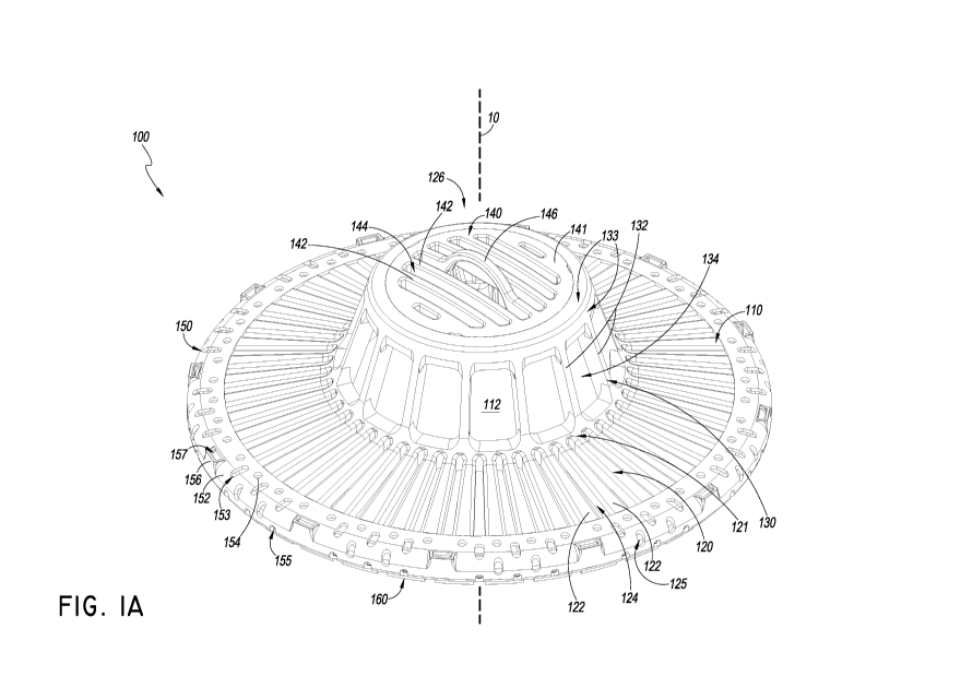
[0084] FIG. 1A is a perspective view of an embodiment of a cover 100
for a drain,
such as a roof drain. The cover 100 may be used with many other types of
drains as well. For
example, the cover 100 may be used with other outdoor drains, indoor drains,
street drains,
street grating, etc. Thus, the cover 100 is not limited to use with any one
type of drain. The
cover 100 has features that allow for the flow of fluid through the cover and
into the drain
even with buildup of debris on or around the cover 100, as described in detail
herein.
[0085] As shown in FIG. 1A, the cover 100 may have a body 110. The
body 110
may be formed from a variety of suitable materials. In some embodiments, the
body 110 may
be formed from plastic, polymers, metals, other materials, and/or combinations
thereof The
various features or parts of the body 110 may be formed from the same,
monolithic piece of
material. For example, the entire body 110 may be formed by molding a material
into the
various shapes of the cover 100. In some embodiments, the body 110 may be
formed by
injection molding various features of the cover 100. However, the various
features or parts of
the body 110 may be formed as separate parts that are attached or otherwise
connected
together. For example, portions of the body 110 may be formed separately from
other
portions which are then joined together in a variety of suitable means, for
example by
adhering, bonding, mechanically connecting such as with fasteners or brackets,
welding, or
other suitable mechanism or method.
[0086] The body 110 may include one or more sections coupled together,
such as
an upper dome section or dome 126 coupled with a lower skirt section or a
skirt 120. As
shown, the body 110 may include the skirt 120. The skirt 120 may be a
relatively lower part
or parts of the cover 100. By "lower" it is understood that this description
is relative to the
orientation shown in FIG. 1A of the cover 100. The cover 100 may be installed
in the
orientation as shown with a drain located underneath the cover 100 as oriented
in the figure.
Therefore, the designations "lower," "upper," and the like may refer to
locations that are
-18-
CA 02974015 2017-07-14
WO 2016/127055 PCT/US2016/016773
relative to a particular orientation and are merely used for convenience to
describe the various
features.
[0087] The skirt 120 may comprise a part or parts that are oriented
generally in
the manner of a flange or other arcuate configuration. By "arcuate" it is
meant that a feature
may be rounded in a variety of ways, roughly similar to an arc. Therefore, the
term "arcuate"
may refer to a circular shape. However, arcuate may also refer to other
rounded shapes, such
as elliptical, circumferential, annular, other forms of rounded, or
combinations thereof
Arcuate does not impose any requirements on the shape of the edges of the
arcuate part.
Thus, arcuate may also refer to a rounded shape having straight ends or edges,
such as a 2D
cross-section extruded about an axis to forma 3D part, but where the resulting
3D part has
straight outer edges such that the planform (i.e. view from top of bottom of
the part) of the
3D part appears to be square- or rectangular-shaped. Therefore, the term
arcuate is not meant
to be limiting the configuration of the various parts to any one particular
shape.
[0088] Various features of the cover 100 may be described with
reference to the
central axis 10, as shown. The axis 10 may be a geometric reference line that
is not a physical
feature of the cover 100. In some embodiments, the axis 10 may be defined by
one or more
parts of the cover 100. In some embodiments, various features of the cover 100
may be
circular with the axis 10 intersecting the center or near the center of the
various circular
portions. However, the various features of the cover 100 need not be circular
but may still be
referred with reference to the axis 10. The axis 10 may be vertically-oriented
as shown.
[0089] The skirt 120 may be coupled with a lower portion 121 of the
upper dome
126. The lower portion 121 may be a generally arcuate section of the cover 100
that extends
in a swept out path about the axis 10. The lower portion 121 may provide an
interface or
juncture with which various portions of the cover 100 may connect. In some
embodiments,
the lower portion 121 may merely be the end of various intersecting or
interconnecting
portions of the cover 100. The lower portion 121 may have a variety of
different shapes of
cross-sections that are extruded in a generally arcuate manner about the axis
10. Theses
shapes may be square, rectangular, circular, rounded, polygonal, other shapes,
or
combinations thereof
-19-
CA 02974015 2017-07-14
WO 2016/127055 PCT/US2016/016773
[0090] The lower portion 121 may be located approximately a
perpendicular
distance R1 from the axis 10. R1 may be a dimension equal to roughly half of
the total width
of the lower portion 121. The distance R1 may be a radius of a circular lower
portion 121.
However, the lower portion 121 may not be circular, and thus in some
embodiments the
distance R1 may not be a radius. R1 may be measured perpendicularly from the
axis 10 to any
region of the lower portion 121, including to regions of the lower portion 121
that are
relatively closer are farther from the axis 10 than other regions of the lower
portion 121.
Further, R1 need not be constant as measured at different angular locations of
the cover 100.
For example, the lower portion 121 may be arcuate but with straight outer
edges such that the
dome 126 appears square or rectangular as viewed from the top. For such a
shape, R1 would
vary depending on which angular location the dimension is measured (i.e. which
cross-section
or side view is used). Thus, R1 may vary with such a configuration as measured
at different
angular locations. In some embodiments, R1 refers to a maximum or minimum
width of the
dome 126. For a non-circular dome 126, R1 may be a maximum or minimum width,
for
example the maximum or minimum perpendicular distance from the axis 10 to
respectively a
closest portion or farthest-most portion of the dome 126.
[0091] The skirt 120 may flare outward and downward from the lower
portion
121 to an outer edge 129 (see FIG. 1E) and/or outer perimeter 125 in a first
direction that is
generally away from the central axis 10 and generally away from the dome 126
(see FIGS. 1B,
1D and 11, for example).
[0092] The skirt 120 may include one or more lower ribs 122. The lower
ribs 122
may be connected to our otherwise coupled with the lower portion 121. The
lower ribs 122
may be elongated members coupled with the lower portion 121 and extending
outward
therefrom. The lower ribs 122 may couple with the lower portion 121 and extend
radially
outward therefrom. There may be multiple lower ribs 122. There may be 48 lower
ribs 122
(only some are visible in FIG. 1A; see FIG. 1C). In some embodiments, there
may be fewer or
more lower ribs 122. For example, there may be ten, twenty, thirty, forty,
fifty, sixty, seventy,
eighty, ninety, one hundred, one hundred fifty, two hundred, five hundred, or
other
intermediate, lower or greater amounts of lower ribs 122. These are merely
some examples
and are not meant to be self-limiting. The lower ribs 122 may have a generally
U-shaped
-20-
CA 02974015 2017-07-14
WO 2016/127055 PCT/US2016/016773
cross-section. In some embodiments, the lower ribs 122 may have other shaped
cross-
sections, such as C-section, shallow U- or C-section, rectangular, square,
rounded shapes
such as circular, elliptical, arcuate, or other shapes, polygonal shapes,
segmented shapes,
hollow cross-section, solid cross-section, partially hollow and partially
solid cross-section,
and/or combinations thereof
[0093] The lower ribs 122 may extend from the lower portion 121 to an
outer
perimeter 125. The outer perimeter 125 may be a portion or portions of the
cover body 110,
such as the skirt 120, extending along the outside of the cover body 110. The
outer perimeter
125 is visible in FIG. 1A through openings in an outer flow ring 150, though
it may also
include regions of the skirt 120 on the inside of the outer ring 150 as
oriented. The outer
perimeter 125 may include the outer edge 129 (see FIG. 1H, for example). The
outer
perimeter 125 may also include portions of the lower ribs 122. The outer
perimeter 125 may
have a variety of cross-sectional shapes, including any of those described
with respect to the
lower portion 121. The outer perimeter 125 may be integral with the various
lower ribs 122 to
which it is connected. In some embodiments, the lower portion 121, the one or
more lower
ribs 122, and the outer perimeter 125 may all be made from the same monolithic
piece of
material. In some embodiments, the lower portion 122 includes the one or more
lower ribs
122 connected to or otherwise coupled with the lower portion 121 and the outer
perimeter
125. The outer perimeter 125 may provide an edge or other end boundary of the
skirt 120.
Various other features or parts of the cover 100 may be connected to or
otherwise coupled
with the outer perimeter 125 or other portions of the skirt 120. In some
embodiments, an
outer flow ring 150 and/or a mount 160 may be coupled with the outer perimeter
125, as
described in further detail herein.
[0094] The cover 100 may include one or more openings or lower spaces
124. The
body 110 may include the one or more lower spaces 124. As shown, the skirt 120
may at least
partially define or form the one or more lower spaces 124. The lower spaces
124 may be
openings extending through various portions of the cover 100 to allow fluid
flow
therethrough. As shown, the lower spaces 124 may be openings extending through
the skirt
120 to allow fluid flow through the skirt 120. The lower spaces 124 may be
defined by various
portions of the cover 100. As shown, the lower spaces 124 may be defined by
features of the
-21-
CA 02974015 2017-07-14
WO 2016/127055 PCT/US2016/016773
skirt 120, such as the lower ribs 122, the lower portion 121, and/or the outer
perimeter 125.
For example, the lower spaces 124 may be defined on two sides by two adjacent
lower ribs
122, on one end buy a portion of the lower portion 121, and on the opposite
end by a portion
of the outer perimeter 125. In this manner, the lower spaces 124 may be
openings defined or
otherwise formed by various physical features of the skirt 120. The lower
spaces 124 may be
completely open as shown. In some embodiments, the lower spaces 124 may have
other
features therein, such as screens, filters, or other features that may affect
the flow of fluid
therethrough. For instance, screens in the lower spaces 124 may facilitate
allowing the passage
of fluid flow while blocking the passage of larger or solid debris, such as
leaves and sticks.
[0095] The dome 129 may include an arcuate sidewall 130. The sidewall
130 may
be located generally above the skirt 120 as oriented in FIG. 1A. The sidewall
130 may provide
features or functionalities that assist with allowing the flow of fluid
through the cover 100
while blocking or preventing the passage of solids or other debris
therethrough. The sidewall
130 may extend along an arcuate path and thereby define a central vertical
axis 10. The
sidewall 130 may extend along a circular path. In some embodiments, the
sidewall 130 may
extend along other arcuate paths that are non-circular and still define the
axis 10. The axis 10
may be a geometric center of the arcuate path swept out by the sidewall 130 or
by portions
thereof, such as by the lower portion 121. Thus, the axis 10 may still be
defined by the
sidewall 130 even with an arcuate sidewall 130 that is non-circular. The
sidewall 130 may
define a plurality of openings or upper spaces 134 extending through the
sidewall 130
configured to allow fluid flow therethrough. The upper spaces 134 may be
generally
rectangular in shape, or other shapes, such as square, polygonal, rounded
shapes, segmented,
or combinations thereof
[0096] The sidewall 130 may include one or more upper ribs 132. As
shown, the
upper ribs 132 may be elongated members extending along the sidewall 130. The
upper ribs
132 may be elongated with a generally rectangular or square cross-section.
However, the
upper ribs 132 may have a variety of other shaped cross-sections, such as
those described with
respect to the lower ribs 122, or other shapes. The upper ribs 132 may be
oriented in an
arcuate manner generally about the central vertical axis 10. In some
embodiments, the upper
-22-
CA 02974015 2017-07-14
WO 2016/127055 PCT/US2016/016773
ribs 132 are arranged in a circular shape about the axis 10. However, other
arrangements of
the upper ribs 132, such as elliptical, oval, or other shapes, may be
implemented.
[0097] The sidewall 130 may be include a lower portion 121. In some
embodiments, the sidewall 130 may be formed from the same monolithic piece of
material as
the lower portion 121. In some embodiments, the sidewall 130 and the skirt 120
are formed
from the same monolithic piece of material. However, the sidewall 130 may also
be coupled
with the lower portion 121 and/or the skirt 120 in a variety of ways, such as
with mechanical
attachments, adhering, fastening, bonding, or other suitable means.
[0098] The sidewall 130 may include any number of the upper ribs 132.
There
may be fourteen of the upper ribs 132 (only some are visible in FIG. 1A; see
FIG. 1C). In
some embodiments, there may be more or fewer upper ribs 132. For example,
there may be 4,
5, 6, 7, 8, 9, 10, 15, 20, 30, 50, or any other number of intermediate or
greater number of
upper ribs 132.
[0099] The upper ribs 132 may be connected on one end to the lower
portion 121
and on the opposite end to various other features of the cover 100. As shown,
one end of the
upper ribs 132 may be connected or otherwise coupled with an upper perimeter
133. The
upper perimeter 133 may be a portion or segment of the sidewall 130 that
extends in an
arcuate manner about the central axis 10. The upper ribs 132 may be coupled
with the upper
perimeter 133 in a variety of manners. As shown, the upper perimeter 133 and
the upper ribs
132 may be formed from the same monolithic piece of material. In some
embodiments, the
upper perimeter 133 may be a separate part that is subsequently attached to or
otherwise
coupled with the upper ribs 132 in a variety of suitable means, such as
bonding, fastening,
adhering, other mechanical means, other suitable means, or combinations
thereof
[0100] As mentioned, the cover 100 may include one or more upper
spaces 134.
that provide openings through the cover 100 through which fluid may flow. As
shown, the
upper spaces 134 may be formed by various features of the body 110. The upper
spaces 134
may be formed by various features of the sidewall 130. For instance, as shown
the upper ribs
132 may partially form the upper spaces 134 on two or more sides of the upper
spaces 134.
The upper spaces 134 may also be defined on one or more sides by the upper
perimeter 133.
As shown, the upper perimeter 133 or a portion thereof may form an upper side
of the upper
-23-
CA 02974015 2017-07-14
WO 2016/127055 PCT/US2016/016773
spaces 134 as oriented, and/or the opposite side of the upper spaces 134 may
be defined by a
portion of the lower portion 121. Therefore, the upper spaces 134 may be
defined by various
surfaces of adjacent upper ribs 132, adjacent portions of the upper perimeter
133, and
adjacent portions of the lower portion 121. As shown, the upper spaces 134 may
have a
generally rectangular shape. The upper spaces 134 may therefore have the
appearance of a
window. However, the upper spaces 134 may have a variety of shapes, such as
square,
rounded, segmented, other shapes, and/or combinations thereof In some
embodiments, the
upper space is 134 may have the same or similar shapes as the lower spaces
124. Further, the
upper spaces 134 may be entirely open with no physical objects therein.
However, the upper
spaces 134 may also be partially or entirely filled with a screen, filter, or
the like to allow the
flow of fluid therethrough while blocking the passage of debris such as
solids. The upper
spaces 134 may contribute to the effectiveness of the cover 100 by receiving
fluid that might
flow over the skirt 120 and/or over any debris or other blockages built up on
the skirt 120.
The upper spaces 134 may also be sized to receive some of the debris such the
debris will
either catch on the upper space 134 and not fall onto the drain or block the
skirt 120, or the
debris may fall through the upper space 134 and be received into the cavity
112 of the cover
100.
[0101] The cover 100 may include a cavity 112. The cavity 112 may be a
space or
spaces formed by various features of the cover 100. As shown, the body 110 may
form the
cavity 112 therein. For instance, the sidewall 130 may surround and define or
form the cavity
112 therein. The cavity 112 may also be formed and or defined by other
features of the cover
100. For example, the skirt 120 may also define a portion or portions of the
cavity 112. In
some embodiments, the cavity 112 may be a space with a volumetric shape that
complements
the underside of the body 110 of the cover 100. The cavity 112 may be a space
defined or
formed by the body 110 or other features of the cover 100 that facilitates the
flow of fluid
therethrough. For example, the cavity 112 may be a space in between various
features of the
cover 100 and the drain over which the cover 100 is positioned. The cavity 112
may be in
fluid communication with the various spaces of the cover, such as the lower
spaces 124 of the
skirt 120 and/or the upper spaces 134 of the sidewall 130. Fluid may flow
through these or
other spaces and into the cavity 112 and then into the drain.
-24-
CA 02974015 2017-07-14
WO 2016/127055 PCT/US2016/016773
[0102] The dome 126 may include a top 140. The top 140 may be an
uppermost
portion or portions of the dome 126 as oriented in FIG. 1A. The top 140 may
provide an
uppermost structure to the cover 100. As shown, the top 140 may be a portion
or portions of
the body 110. The top 140 and the various features thereof may be formed from
the same or
similar materials as the other portions of the cover 100. For example, the top
140 may be
formed from the same materials as the sidewall 130 and/or the skirt 120. In
some
embodiments, the top 140 is formed from the same monolithic piece of material
as the
sidewall 130 and/or as the skirt 120. As shown, the top 140 may include
portions that are
formed from the same monolithic piece of material as the sidewall 130 and the
skirt 120, and
the top 140 may include other portions that are separate therefrom. Therefore,
a variety of
configurations of the top 140 may be implemented.
[0103] The top 140 may also include the upper perimeter 133 or
portions thereof
Therefore, the upper perimeter 133 may form a portion of the sidewall 130 as
well as a
portion of the top 140. Thus, the top 140 may have a generally arcuate shape
such as those
described above with respect to the sidewall 130 and the upper perimeter 133.
In some
embodiments, the upper perimeter 133 may extend entirely across the top 140
such that the
top 140 forms a surface, which may be curved, flat or other shapes. As shown
and described
below, the top 140 may have other features and or separable components.
[0104] As shown, the top 140 may include a lid 141. The lid 141 may be
a portion
or portions of the top 140. The lid 141 may be generally centrally-located or
it may be in
other locations of the top 140. As shown, the lid 141 may have a generally
arcuate shape, such
as circular or other shape, that is complementary to the arcuate shape of the
upper perimeter
133. The lid 141 may be removable. Removal of the lid 141 or other features
from the cover
100 may facilitate with observing and/or accessing the cavity 112 and/or the
drain thereunder.
For instance, a user may remove the lid 141 in order to observe the drain
and/or internal
features of the cover 100. Also the ability to remove the lid 141 allows an
anti-vortex plate or
other devices to be installed. In some embodiments, the lid 141 may be a
generally circular
part of the upper portion of the top 140 which is removable therefrom. For
example, the lid
141 may interface with the upper perimeter 133 at a generally circular
boundary. The lid 141
may also interface with the upper perimeter 133 or other portions of the cover
100 in a variety
-25-
CA 02974015 2017-07-14
WO 2016/127055 PCT/US2016/016773
of other manners, including with other suitable shapes and configurations of
this and/or other
interfaces.
[0105] The cover 100 may include one or more top ribs 142. The top
ribs 142 may
be generally elongated members located at or near the top 140. The top ribs
142 may have a
variety of cross-sectional shapes, such as rectangular, or any of those
described herein, for
example with respect to the upper ribs 132 and/or the lower ribs 122. As
shown, the top ribs
142 may be oriented generally parallel to each other. However, a variety of
other
arrangements may be implemented with the top ribs 142. As further shown, the
top ribs 142
may have a variety of lengths. Some of the top ribs 142 may be longer or
shorter than other
top ribs 142. As shown, the top ribs 142 generally near the center of the top
140 may be
longer than those top ribs 142 located generally farther from the center. As
shown, there may
be six top ribs 142. In some embodiments, there may be more or fewer top ribs,
for example,
none, one, two, three, four, five, seven, eight, nine, ten, fifteen, twenty,
twenty-five, fifty, one
hundred, or intermediate or greater numbers of top ribs 142. The top ribs 142
may be
connected on one end to a first portion of the upper perimeter 133 and on the
opposite end to
an opposing portion of the upper perimeter 133. As shown, the top ribs 142 may
be connected
on one end to one portion of the lid 141 and on the opposite end to an
opposing portion of
the lid 141.
[0106] The cover 100 may include one or more top spaces 144. The top
spaces
144 may be openings through the top 140 of the cover 100 that allow the
passage of fluid
therethrough. The top spaces 144 may prevent the passage of large solids
therethrough such
as large pieces of debris, large sticks, and the like. The top spaces 144 may
be large enough to
allow some debris to pass therethrough in order to prevent a large buildup on
the skirt 120.
As shown, the top spaces 144 may be formed by various features of the body
110, such as the
top 140. For example, the top spaces 144 may be formed by one or more top ribs
142 and/or
by one or more surfaces of the lid 141. In some embodiments, the top spaces
144 may be
formed by one or more top ribs 142 and various surfaces of the upper perimeter
133. These
are just some examples and the top spaces 144 may be defined in other ways,
such as by
combinations of the top ribs 142, the lid 141, and/or the upper perimeter 133.
In some
embodiments, some or all of the top spaces 144 may be defined on two opposing
sides by two
-26-
CA 02974015 2017-07-14
WO 2016/127055 PCT/US2016/016773
adjacent top ribs 142. In some embodiments, the ends of the top spaces 144 may
be defined by
two opposing sides or portions of the lid 141 or of the upper perimeter 133.
Some of the top
spaces 144 may be defined on one side by the top rib 142 and on the opposite
side by a
portion of the lid 141. In some embodiments, some of the top spaces 144 may be
defined in
part by a top rib 142 on one side and on the opposite side by a portion of the
upper perimeter
133. The top spaces 144 may be entirely open therethrough, as shown. In some
embodiments,
the top spaces 144 may include screens or filters therein to facilitate with
allowing the passage
of fluid therethrough while preventing or blocking the passage of solids and
the like, similar to
the upper spaces 134 and/or the lower spaces 124 described herein.
[0107] The cover 100 may include a handle 146. As shown, the handle
146 may be
a feature of the body 110. For example, the handle 146 may be a feature of the
top 140. The
handle 146 may provide a structure by which a user can pick up or otherwise
handle the cover
100. In some embodiments, the handle 146 may allow a user to remove the lid
141 from the
cover 100. For example, a user may grab the handle 146 to remove the lid 141
from the top
140. The handle 146 may also be used to put the lid 141 or other portions of
the cover 100
back onto the cover 100.
[0108] The handle 146 may have a variety of shapes and sizes. As
shown, the
handle 146 may be an arc that extends away from the top 140. The handle 146
may be an
arcuate shape extending upward as oriented from one or more of the top ribs
142. In some
embodiments, the handle 146 may be a top rib 142 with a different contour than
the other top
ribs 142. As shown, the handle 146 may be partially flat on the ends with a
middle portion that
extends upward and in a generally arcuate shape. However, the handle 146 may
extend
upward in a variety of shapes and contours, such as square, rectangular,
segmented, other
polygons, other shapes, or combinations thereof Therefore, the configuration
shown and
described is merely one possible implementation and other suitable
configurations may be
implemented.
[0109] The cover 100 may include an outer ring 150. The outer ring 150
may be a
structure or structures configured to couple with the cover body 110 generally
along the outer
perimeter 125. The outer ring 150 may be arcuate in shape. The outer ring 150
may be a
separable part of the cover 100 which may be removed therefrom and reattached
thereto.
-27-
CA 02974015 2017-07-14
WO 2016/127055 PCT/US2016/016773
The outer ring 150 may be arcuate when attached to the cover and either
arcuate or other
shapes, such as straight, when removed from the cover 100. When coupled with
the cover
100, the outer ring 150 may be located a perpendicular distance R2 from the
axis 10. When
coupled with the cover 100, the outer ring 150 may have an outer surface that
is located a
perpendicular distance R2 from the axis 10. R2 may be a dimension equal to
roughly half of
the overall width of the outer ring 150. The distance R2 may be a radius of a
circular outer
ring 150. However, the outer ring 150 may not be circular, and thus in some
embodiments the
distance R2 may not be a radius. Further, R2 need not be constant as measured
at different
angular locations of the cover 100. For example, the outer ring 150 or other
parts such as the
skirt 120 may be arcuate but with straight outer edges such that the ring 150
or skirt 120
appears square or rectangular as viewed from the top. For such a shape, R2
would vary
depending at which angular location the dimension is measured (i.e. which
cross-section or
side view is used to make the measurement). Thus, R2 may vary with such a
configuration as
measured at different angular locations. In some embodiments, R2 refers to a
maximum or
minimum width of the outer ring 126, or other outer portion of the skirt 1220.
For a non-
circular dome 126, R1 may be a maximum or minimum width, for example the
maximum or
minimum perpendicular distance from the axis 10 to respectively a farthest-
most or closest
portion of the outer ring 126, or other outer portion of the skirt 1220.
[0110] The outer ring 150 may be an elastic or otherwise flexible
material. The
outer ring 150 may expand to attach to various features of the cover 100 such
as the outer
perimeter 125 or other features. The outer ring may couple the ring body 110
with a mount
160, as described herein. The outer ring 150 may provide structural stability
to various
features of the cover 100 such as the outer perimeter 125. The outer ring 150
may include
features that facilitate the flow of fluid through the cover 100 while
preventing the flow of
solids therethrough. In some embodiments, the outer ring 150 may include
features that
facilitate installation and securement of the cover 100.
[0111] The outer ring 150 may include a ring body 152. The ring body
152 may be
a generally arcuate structure configured to couple with the cover 100, such as
with the outer
perimeter 125 of the skirt 120. In some embodiments, the ring body 152 may
couple with the
outer edge 129 of the skirt 120. The ring body 152 may at least partially
cover the outer edge
-28-
CA 02974015 2017-07-14
WO 2016/127055 PCT/US2016/016773
129 and/or the outer perimeter 125 when coupled with the skirt 120. The ring
body 152 may
have a generally U- or C-shaped cross-section that extends in an arcuate
manner and is swept
out angularly about the central axis 110 (see FIG. 1E, for example). The ring
body 152 may
expand to couple around the skirt 120 of the cover 100. The ring body 152 may
contract to
compress around and thereby secure to the skirt 120 or other features of the
cover 100. The
outer ring 150 may also couple with a mount 160. In some embodiments, the
outer ring 150
may couple the ring body 110 with the mount 160.
[0112] The outer ring 150 may include a variety of slots 153, holes
154, and/or
openings 155. The ring body 150 may form or define these and other features.
For example,
various surfaces of the ring body may define inner surfaces of the slots 153,
the holes 154,
and/or the openings 155. As shown, the slots 153 may be elongated spaces
within the ring
body 152 and extending therethrough. The holes 154 may be generally circular
spaces
extending through the ring body 152. The openings 155 may be partially
circular and partially
linear spaces extending through the ring body 152. As shown, the slots 153 may
be located
along top and outer portions of the ring body 152 as oriented in the figure
and in a generally
arcuate configuration about the central axis 10. The holes 154 may be located
more inwardly
on the ring body 152 as oriented in the figure and in a generally arcuate
configuration about
the axis 10. The openings 155 may be located more outwardly on the ring body
152 as
oriented in the figure and in a generally arcuate configuration about the axis
10. These
arrangements and configurations of the slot slots 153, the holes 154 and the
openings 155 are
merely some examples, and a variety of configurations and arrangements of the
various spaces
may be incremented.
[0113] The slots 153, the holes 154, and/or the openings 155 may
provide spaces
through the ring body 152 that allow the passage of fluid therethrough while
preventing the
flow of solids therethrough. These spaces of the outer ring 150 may therefore
improve the
performance of the cover 100 through advantageous sizing and/or locating of
the various
spaces of the outer ring 150. The slots 153, the holes 154, and the openings
155 may be in
fluid communication with the cavity 112. For instance, these spaces may be in
fluid
communication with the lower spaces 124 which may in turn be in fluid
communication with
-29-
CA 02974015 2017-07-14
WO 2016/127055 PCT/US2016/016773
the cavity 112. Thus, the cover 100 may allow for fluid flow through the outer
ring 150 while
preventing or reducing the flow of gravel or other debris through the outer
ring 150.
[0114] The outer ring 150 may include one or more pockets 157. The
pockets 157
may be located generally along the outer surface or services of the ring body
152 and an
arcuate configuration about the axis 10. The pockets 157 may extend generally
upward and
form a recess therein. The pockets 157 may assist with handling the outer ring
150. In some
embodiments, the pockets 157 may assist with assembling and/or disassembling
the outer ring
150 with the ring body 110 and/or the mount 160. The pocket 157 may provide a
surface for
a user or tool to grasp or to pry the outer ring 150 into or out of place on
the cover 100.
[0115] The outer ring 150 may not have any sharp edges. The edges of
the
various features of the outer ring 150 may therefore be rounded or otherwise
smoothed. This
may mitigate the chances of debris getting caught on the outer ring 150. The
outer ring 150
may further by relatively shallow or short to mitigate the chances of debris
getting caught
thereon.
[0116] The cover 100 may include a mount 160. The mount 160 is
partially visible
in FIG. 1A. The mount 160 may secure the cover 100 to a mounting structure,
such as a
roof or floor. The mount 160 may have a generally arcuate shape. The mount 160
may have
an arcuate or other shape before being assembled with other components of the
cover 100.
The mount 160 may provide a structure to and from which the ring body 110 may
be easily
coupled and removed. For instance, the mount 160 may provide a feature or
features to which
the body 110 or other features of the cover 100 may be snapped. Therefore, the
body 110 may
be snapped into place with the mount 160 to easily secure the cover 100 in
place. Similarly,
the body 110 may be snapped off of the mount 160 to remove the body 110
therefrom. The
mount 160 may have a lower side that attaches to a mounting structure, such as
a roof,
sidewalk, or other features surrounding a drain intended to be covered with by
the cover 100.
The opposite side of the mount 160 may include these various features to which
the body 110
may be coupled. Further detail of the mount 160 is described herein. In some
arrangements,
the mount 160 can be secured to the mounting structure by screws, nails,
adhesives and/or
other fastening devices or methods. Thus, in some embodiments of use, the
mount 160 can be
coupled to a mounting structure surrounding a drain. The cover 100 can be
coupled to the
-30-
CA 02974015 2017-07-14
WO 2016/127055 PCT/US2016/016773
mount 160 so that the cover 100 can cover the drain. The cover 100 may attach
to the mount
by friction fit, for instance by snapping projections of the cover into
corresponding receiving
structures of the mount as described herein. As described herein, this
arrangement can allow
fluids to flow through the cover 100 and into the drain even in the presence
of buildup of
solids or other foreign debris along and/or on the outside of the cover while
also reducing the
amount of debris buildup around the drain and cover 100.
[0117] FIG. 1B is a side view of the cover 100. As shown, the central
vertical axis
may extend through the center of the cover 100 as oriented. Other geometric
features may
assist with describing the cover 100. As shown, there may be a horizontal
plane 15. The
horizontal plane 15 may be a geometric reference plane that is generally
perpendicular to the
axis 10. The horizontal plane 15 may be generally defined by one or more
features of the
cover 100. As shown, the horizontal plane may be generally formed by a lower
surface or
surfaces of the mount 160. In some embodiments, the horizontal plane 115 may
be formed or
otherwise defined by various lower services of the outer ring 150 as oriented.
In some
embodiments, the horizontal plane 15 may be defined by various features of the
skirt 120,
such as the outer perimeter 125. It is understood that the precise vertical
location of the
horizontal plane 15 along the axis 10 may be located in a variety of locations
of the cover 100.
Further, the various feature or features of the cover 100 that may define the
horizontal plane
need not all be in a precise exact plane, rather the various features may be
generally within
the plane 15. Further, it is understood that the various features defining the
horizontal plane
15 may do so when the cover 100 is in an unrestrained state. The various
features defining the
plane 15 may be contorted or otherwise manipulated or bent when the cover 100
is attached
to a mounting structure. When the cover 100 is attached to a mounting
structure the various
features defining the plane 15 may no longer be planar. For instance, the
cover 100 may be
attached to a curved mounting structure in which the mount 160 or other
features of the cover
100 may not reside in an exact plane in the attached configuration. Thus, it
is understood that
the plane 15 is defined with respect to the cover 100 in an unrestrained state
before the cover
100 is secured to a mounting structure.
[0118] As shown in FIG. 1B, the skirt 120 may be angled with respect
to the axis
10 and/or the horizontal plane 15. As shown, portions of the skirt 120, such
as the lower ribs
-31-
CA 02974015 2017-07-14
WO 2016/127055 PCT/US2016/016773
122, when viewed from the side may be oriented at an acute angle A with
respect to the axis
10. "Acute" is used in its usual and customary sense as indicating an angle
that is less than
90 . The skirt 120 may extend about the axis 10 in a generally arcuate
configuration, as
mentioned. Therefore, the skit 120 may provide a number of surfaces which are
oriented at
the angle A with respect to the axis 10 that also extend about the axis 10 in
a generally arcuate
configuration. The skirt 120 may skirt flare outward and downward from the
lower portion
121 to the outer edge 129 of the skirt in a first direction that is generally
away from the
central axis 10 and generally away from the dome 26, wherein the first
direction forms the
acute angle A with the axis 10. As further shown, the angle A may be acute
when measured
from a portion of the axis 10 that is under or below the cover 100, as
oriented in FIG. 1B.
The angle A may be acute when measured from a portion of the axis 10 that is
under or below
the horizontal plane 15, as oriented in FIG. 1B.
[0119] The angle A may be sized in order to optimize or otherwise
facilitate the
flow of fluid through the cover 100 while preventing the buildup of solids or
other debris from
blocking the flow of fluid through the cover 100. For example, the angle A may
be relatively
large such that a buildup of solids or other debris on or near the skirt 120
will still allow for
the flow of fluid through the skirt 120. For instance, leaves and sticks or
other debris may
build up onto the skirt 120. By having a relatively large angle A, the buildup
of debris on the
skirt 120 will still allow the flow of fluid through the cover 100 due to
gravity causing the
fluid to drip through the buildup of debris and through the lower spaces 124
of the skirt 120.
Therefore, the angle A may be sized such that such a buildup may be produced
on top of or
otherwise near the skirt 120 in order to allow the downward flow and/or
dripping of fluid
through the buildup and subsequently through the skirt 120, into the cavity
112 therein, and
ultimately into the drain.
[0120] In some embodiments, the angle A is greater than or equal to 60
.
However, the angle A may have a variety of sizes. In some embodiments, the
angle A may be
greater than or equal to 65 , greater than or equal to 70 , greater than or
equal to 75 , greater
than or equal to 80 , greater than or equal to 85 , or other smaller,
intermediate or larger
angular amounts. These are just some examples and are not limiting of the
scope of this
disclosure. For instance, in some contexts a larger angle A may be implemented
that still
-32-
CA 02974015 2017-07-14
WO 2016/127055 PCT/US2016/016773
produces the advantageous effects. For example, depending on the contour of
the mounting
structure to which the cover 100 is mounted or otherwise secured, the angle A
may need to be
less than 60 . In some embodiments, the angle A may therefore be less than 60
, such as 550
,
50 , 45 or other angular amounts.
[0121] While the angle A may be generally constant for the entirety of
the skirt
120 about the axis 10, the angle A need not be constant. For example, the
angle A may have
one value at one angular location of the skirt 120 about the axis 10, and a
different value at a
different angular location of the skirt 120 about the axis 10. Therefore, a
variety of
configurations and arrangements of the skirt 120 related to the angle A may be
implemented.
[0122] It is understood that the orientation of the skirt 120, such as
the orientation
of the lower ribs 122, may be described with respect to other geometric
references or features
of the cover 100. For instance, the orientation of the skirt 120 may be
described with respect
to the axis 10 or plane 15, or with respect to the mount160, the sidewall 130,
the top 140,
and/or other features or references. The particular references and features
used to describe the
orientation of the skirt 120 or parts thereof are merely for convenience and
are not meant to
limit the scope of the disclosure.
[0123] Further shown in FIG. 1B is the sidewall 130. As shown, the
upper ribs
132 of the sidewall 130 may extend in a generally vertical direction when
viewed from the
side. The upper ribs 132 are shown oriented at an acute angle B with respect
to the axis 10.
The angle B may be acute when measured from a portion of the axis 10 that is
over or above
the cover 100, as oriented in FIG. 1B. The angle B may be acute when measured
from a
portion of the axis 10 that is over or above the horizontal plane 15, as
oriented in FIG. 1B.
Other features of the sidewall 130 may also be oriented at the angle B. The
angle B may be
chosen so as to optimize or otherwise facilitate the flow of fluid through the
cover 100 while
preventing the flow of solids or other debris therethrough. In some
embodiments, the angle B
may be 0 such that the upper ribs 132 or other features of the sidewall 130
are vertical, or
parallel to the axis 10, or perpendicular to the horizontal plane 15. In some
embodiments, the
angle be may be 5 , 10 , 15 , 20 , 25 , 30 , or other intermediate, lower or
greater angular
amounts. In some embodiments, the angle B may be equal to the angle A. In some
-33-
CA 02974015 2017-07-14
WO 2016/127055 PCT/US2016/016773
embodiments, the angle B may not be equal to the angle A. The angle B may be
greater or
less than the angle A.
[0124] The sidewall 130 may include the upper ribs 132 having sides
133. The
sides 133 may be opposing sides or surfaces of the upper ribs 132. The sides
133 may partially
define upper spaces 134 on either side of an upper rib 132. The distance
between the sides
133 of the upper ribs 132 may define a width of the upper ribs 132. Further,
the two sides 133
of the upper ribs 132 may be oriented in a variety of manners with respect to
each other. In
some embodiments, the sides 133 may be parallel to each other such that the
upper rib 132 has
a uniform width along the length of the upper rib 132.
[0125] In some embodiments, the two sides 133 of the upper rib 132 may
not be
parallel to each other such that the upper rib 132 does not have a uniform
width along the
length of the upper rib 132. As shown, the two sides 133 of a single upper rib
133 may be
oriented at an acute angle C with respect to each other. The angle C may be
sized so as to
optimize or otherwise facilitate the flow of fluid through the cover 100. For
example, the size
of the angle C may be sized to optimize or otherwise facilitate the flow of
fluid through the
upper spaces 134 or other features of the sidewall 130. In some embodiments,
the angle C
may be 1 , 2 , 3 , 4 , 5 , 10 , 15 , 20 , or other intermediate, smaller or
greater angular
amounts.
[0126] Because the upper ribs 132 may define one or more surfaces of
the upper
spaces 134, the angle at which the sides 133 are oriented may affect the shape
of the upper
spaces 134. Therefore, the various surfaces defining the upper spaces 134 may
have a variety
of configurations and/or orientations. In some embodiments, the upper spaces
134 may be
generally rectangular, as mentioned. In some embodiments, the upper spaces 134
may be
trapezoidal, or other shapes. Further, the upper ribs 132 as mentioned may be
coupled on one
end with the lower portion 121 and on the opposite end with the upper
perimeter 133. The
upper ribs 132 may be wider on the end coupled with the lower portion 121 as
compared with
the end of the upper rib 132 coupled with the upper perimeter 133, or vice
versa. Therefore, it
is understood that the angle C may refer to either a thinning or widening
upper rib 132 in the
direction from the lower portion 121 to the upper perimeter 133
-34-
CA 02974015 2017-07-14
WO 2016/127055 PCT/US2016/016773
[0127]
Further visible in FIG. 1B is a portion of the top 140. As shown, the top
ribs 142 may project slightly upward as oriented. The top ribs 142 may
therefore have a
slightly arcuate contour along the length of the top ribs 142. Therefore, the
top spaces 144
that may be defined by the top ribs 142 may have a complementary or
corresponding shape.
[0128]
Further shown in FIG. 1B is the mount 160. As shown, the mount 160 may
have a mount body 162. The mount body 162 may be a generally arcuate structure
configured
to couple with a mounting structure on one side and on the opposite side to
various features
of the body 110 of the cover 100. The mount body 162 may have a lower side
that defines the
horizontal plane 15. Further detail of the mount 160 is described herein, for
example with
respect to FIG. 2.
[0129] The
overall height of the cover 300 as oriented in the figure may be about
4-5". The cover 300 may have other heights as well, such as 1", 2", 3", 6",
7", 8", 9", 10",
15" or other smaller, intermediate or greater heights. The overall width of
the cover 300 as
oriented in the figure may be from about 5" to about 13". The cover 300 may
have other
overall widths as well, such as 1", 2", 3", 4", 6", 7", 8", 9", 10", 11", 12",
14", 15", 20", 25",
30" 50", or other smaller, intermediate or greater widths. These values for
the overall width
dimensions may apply to the dimension D2 shown in FIG. 1C and discussed in
further detail
herein. Further, the dimension R2 may have values that are half or about half
of these values
for the overall width values.
[0130]
FIG. 1C is a top view of the cover 100. As shown, the cover 100 may have
a generally arcuate shape, which may be circular. As shown, the cover 100 may
have a
generally circular shape when viewed from the top that is generally symmetric
with respect to
the axis 10. The axis 10 appears as a point in the figure because it is being
viewed in a plane
that is perpendicular to the axis 10. The cover 100 may have other arcuate
shapes with respect
to the axis 10, such as elliptical, oval, circumferential, other rounded
shapes, or combinations
thereof
[0131] The
skirt 120 may similarly have a generally arcuate shape about the axis
10. The
skirt 120 may provide an extended area that is greater than the area of just
the drain,
over which the cover 100 may be positioned. By "extended area" in this
context, it is meant
the two dimensional surface area that the skirt 120 "sweeps" out. Thus, the
"extended area" is
-35-
CA 02974015 2017-07-14
WO 2016/127055 PCT/US2016/016773
not limited to only the surface area of the top surfaces of the skirt 120,
such as the top
surfaces of the ribs 122. It also includes the area of the skirt 120 over any
openings in the
skirt 120, such as the spaces defined or formed by the ribs 122 or by other
features of the skirt
120. This extended area may be approximately equal to the area of the skirt
120 as viewed
from the top view as shown in FIG. 1C, but the actual area will be higher
because the skirt
120 may be angled.
[0132] In some embodiments, the skirt 120 may provide an extended area
that is
greater than the area of the drain. The "area of the drain" here may refer to
the overall general
area covered by the draining region of the drain, which includes but is not
limited to any
openings in the drain. For example, the area of the drain may be based on the
width W of the
drain, discussed herein with respect to FIG. 9A. In some embodiments, the
skirt 120 may
provide an extended area that is two, three, four, five, six, seven, eight,
nine, or ten times as
large as the area of the drain, or any smaller, intermediate or larger values.
Tables 1 and 2
below show some examples of the relative size of the widths R1 and R2 as
expressed by the
ratio of R2 / R1 that may be implemented and the approximate corresponding
increase in area,
or the Area Factor "AF." The designs shown are approximations as to the
corresponding AF
because the width of the drain is assumed to be similar to R1, i.e. that the
drain is circular and
has a diameter equal to twice the value of Rl. Table 1 shows the resulting AF
for a particular
ratio of R2 / R1. Table 2 shows the resulting ratio R2 / R1 for a particular
AF. Either
quantity R2 / R1 or AF may be chosen as a design goal and then the
corresponding quantity
calculated. Further, these are just some examples and are not meant to be self-
limiting. Other
values that may be used may be smaller, larger or in between the values shown
in Tables 1 and
2.
R2 / R1 1.50 1.75 2.00 2.25 2.50 2.60 2.75 2.80 2.90 3.00
AF 1.3 2.1 3.0 4.1 5.3 5.8 6.6 6.8 7.4
8.0
Table 1. Area Factor For a Given Ratio R2 / R1
AF 1.5 2.0 3.0 4.0 5.0 6.0 7.0 8.0 9.0 10.0
R2 / R1 1.58 1.73 2.00 2.24 2.45 2.65 2.83 3.00 3.16 3.32
Table 2. Ratio R2 / R1 for a Given Area Factor
[0133] R2 and R1 may also be expressed relative to each other. R2 may
be
expressed relative to a multiple of R1. Thus, for example, R2 may be at least
twice R1, i.e.
-36-
CA 02974015 2017-07-14
WO 2016/127055 PCT/US2016/016773
R2 may be greater than or equal to 2 x R1. In some embodiments, R2 may be
greater than or
equal to 2.25 x R1, R2 may be greater than or equal to 2.5 x R1, R2 may be
greater than or
equal to 2.75 x R1, R2 may be greater than or equal to 3 x R1, R2 may be
greater than or
equal to 3.5 x R1, R2 may be greater than or equal to 4 x R1, etc. R2 may
further be capped
at a maximum amount. Thus R2 may be greater than or equal to 2 x R1 but less
than or equal
to 3 x R1. In some embodiments, R2 may be greater than or equal to 2 x R1 but
be less than
or equal to 2.25 x R1, less than or equal to 2.5 x R1, less than or equal to
2.75 x R1, less than
or equal to 3.5 x R1, less than or equal to 4 x R1, less than or equal to 5 x
R1, etc. In some
embodiments, R2 may be greater than or equal to 3 x R1 but be less than or
equal 3.5 x R1,
less than or equal to 4 x R1, less than or equal to 5 x R1, etc. These are
merely some
examples and the min or max value of R1 may be lower, intermediate, or greater
multiples of
R2 besides those explicitly given herein and some examples can also include
the various
ranges and sub-ranges between the various minimum and maximum values of R2
described
above.
[0134] The increased area relative to the drain provided by the skirt
120 may
increase the chances of draining surrounding fluids through the drain. This
may be due in part
because a shallow-sloped skirt 120 may allow debris to flow over and past the
skirt 120, and
further a larger area (as compared with the drain area) will now need to be
covered or
clogged. Therefore, not only may the orientation of the skirt 120 contribute
to the
effectiveness of the cover 100, but the overall area of the skirt 120 may
contribute as well.
[0135] Some embodiments disclosed herein include a method of coupling
a cover
for a drain to a mounting surface, the method comprising: coupling the cover
100 to the
mounting surface such that the cover at least partially surrounds the drain.
In some
embodiments, the cover 100 is coupled to the mounting surface via a mount 160
as described
herein. In some arrangements, the drain has a half-width of R1 and wherein the
cover 100
includes an arcuate dome defining a central axis and an arcuate skirt coupled
with the dome
and having an outer edge, wherein the skirt flares outward and downward from
the dome to
the outer edge in a first direction that is generally away from the central
axis and generally
away from the dome, wherein the first direction forms an acute angle A with a
portion of the
central axis that extends below the skirt, wherein the skirt forms a plurality
of openings
-37-
CA 02974015 2017-07-14
WO 2016/127055 PCT/US2016/016773
extending through the skirt, and wherein the outer edge of the skirt is
located a perpendicular
distance R2 from the axis, and wherein R2 is at least twice R1. In modified
embodiments, R2
can be within the values and ranges described herein.
[0136] As shown, the lower ribs 122 may be oriented such that they
extend
radially with respect to the central axis 10. The lower ribs 122 and/or other
features of the
skirt 120 may be described as sweeping out an angle of 360 about the axis 10.
Therefore, the
skirt 120 may be described as sweeping out an angle of 360 about the axis 10.
Similarly, the
sidewall 130, the top 140, and or the outer ring 150 may be described as
sweeping out an
angle of 360 about the axis 10. By sweeping out an angle of 360 it is meant
that the closed
shape such as a circle or other rounded shape is formed about or generally
about the axis 10.
In some contexts, a cover 100 having a full 360 swept shape may be used over
a drain on a
mounting structure that has no interfering structures nearby, such as on an
open part of the
roof away from any walls of a building. However, in other contexts a drain may
be located
next to an interfering structure such as a wall, for example at the
intersection of a roof and a
wall on the roof In these or other instances, less than 360 of swept out
shape of the cover
100 may be implemented, as described in further detail herein for example with
respect to
FIGS. 4-6.
[0137] As shown in FIG. 1C, the lower ribs 122 may have one or more
sides 123.
The sides one 123 may be a surface or surfaces of the lower ribs 122. As
shown, two sides
123 of a single lower rib 122 may be located on opposite sides of that single
lower rib 122.
The sides 123 of the lower ribs 122 may partially define the lower spaces 124
that are adjacent
to the lower rib 122. As shown, the sides 123 may be generally straight.
However, the sides
123 may be rounded, segmented, partially rounded and impartially straight,
other shapes, or
combinations thereof
[0138] The lower ribs 122 may include a first end 122A. The first end
122A may
couple the rib 122 with the lower portion 121. The lower ribs 122 may also
include a second
end 122B. The second end 122B may be located on an end of the lower rib 122
that is
opposite from the first end 122A. The second end 122B of the lower ribs 122
may couple the
lower ribs 122 with the outer perimeter 123 (only partially visible in FIG.
1C). The first end
122A and the second end 122B may each have a width defined in part by the
distance between
-38-
CA 02974015 2017-07-14
WO 2016/127055 PCT/US2016/016773
the sides 123 at the respective ends of the lower rib 122. The width of the
lower rib 122 at the
first end 122A may be less than the width of the lower rib 122 at the second
end 122B. In
some embodiments, these two widths may be the same or approximately the same.
In some
embodiments, the first end 122A may have a width that is greater than the
width of the second
end 122B of the lower rib 122.
[0139] As shown, the sides 123 of the rib 122 may be oriented with
respect to
each other at an acute angle D. The angle D may be sized so as to optimize or
otherwise
facilitate the flow of fluid through the skirt 120 and to prevent the flow of
solids therethrough.
The angle D may be chosen such that the lower spaces 124 defined by the skirt
120 are
optimized in this manner. As shown, the first end 122A may be relatively
thinner or less wide
than the second end 122B of the lower rib 122, such that the angle D between
the sides 123 is
measured as shown in FIG. 1C. However, the first end 122A may be relatively
wider than the
second end 122B of the lower rib 122 such that the angle D may be oriented
differently. In
either configuration, the descriptions for the angle D may apply equally. In
some
embodiments, the angle D may be 1 , 2 , 3 , 4 , 5 , 10 , 15 , 20 , or any
other intermediate,
lower or higher angular amount. Further, the angle D may be the same for all
of the lower ribs
122 of the cover 100, as shown. However, in some embodiments, the angle D may
be
different for different lower ribs 122 of the same cover 100.
[0140] Further shown in FIG. 1C are the lower spaces 124. The lower
spaces 124
may have a variety of shapes and configurations. The lower space 124 may
include a first end
124A and an opposite second end 124B. The first end 124A may be located
adjacent to or
otherwise near the lower portion 121. The second end 124B may be located
adjacent to or
otherwise near the outer perimeter 125. As mentioned, the lower spaces 124 may
be defined
in part by the sides 123 of adjacent lower ribs 122. The distance between two
opposing sides
123 of two adjacent ribs 122 may define a width of the lower space 124 defined
therein. The
width of the lower space 124 at the first end 124A may be the same as the
width of the lower
space 124 at the second end 124B. In some embodiments, the width of the first
end 124A of
the lower space 124 may be greater than the width of the lower space 124 at
the second end
124B. In some embodiments, the width of the first end 124A of the lower space
124 may be
less than the width of the second end 124B of the lower space 124.
-39-
CA 02974015 2017-07-14
WO 2016/127055 PCT/US2016/016773
[0141] In embodiments where the widths of the first end 124A and of
the second
end 124B are not equal, the lower space 124 may be defined with respect to the
angle E as
indicated. The angle E may be an angle defined by two opposing sides 123 of
two adjacent
lower ribs 122 that partially define the lower space 124 therebetween. The
angle E may apply
equally to lower spaces 124 where the first end 124A is wider than the second
end 124B, and
vice versa. In some embodiments, the angle E may be 1 , 2 , 3 , 4 , 5 , 10 ,
15 , 20 , or other
intermediate, lower or higher angular amounts. Further, the angle E may be the
same for each
of the lower spaces 124. However, in some embodiments the angle E may be
different for
different lower spaces 124. Therefore, one of the lower spaces 124 may have a
first value for
the angle E, while another lower space 124 may have a different value for the
angle E.
[0142] The cover 100 may have a diameter D1 and an overall diameter
D2. The
diameter D2 may be a distance perpendicular to the axis 10 from one end of the
cover 100 to
the opposite end. The diameter D1 may be a distance perpendicular to the axis
10 from one
end or region of the lower portion 121 to the opposite end or region of the
lower portion 121.
By "diameter" in this context it is understood that this may refer to an
ordinary diameter of a
circle, but that it may also refer to the width of a non-circular cover 100,
such as the major or
minor axis of an elliptical cover 100. Therefore, the nomenclature of the
diameter D2 is not
meant to limit the cover 100 to any particular shape. Further, the diameters
D1 and D2 may
vary when measured at different angular locations, for instance with an
elliptical cover 100.
[0143] The diameter D1 and/or the overall diameter D2 of the cover 100
as
oriented in FIG. 1C may be various sizes to accommodate various sizes of
drains. In some
embodiments, the overall diameter D2 of the cover 100 may be about 13" which
could fit, for
example, over a drain that is 2-6" wide. The overall diameter D2 of the cover
100 may be
other amounts as well, such as 8", 9", 10", 11", 12", 14", 15", 16", 17", 18",
19", 20", 25",
30" or other intermediate, lower or greater amounts. The cover 100 may also
fit over drains
of various widths, such as 1", 7" or greater.
[0144] FIG. 1D is a section view of the cover 100 as taken along the
line 1D-1D
as indicated in FIG. 1C. As shown, the dome 129 and/or the skirt 120 may
define the cavity
therein. The dome 129 may be a shell-like structure attached to the skirt 120.
The ribs 122 as
shown may include an elongated thin section extending toward the outer ring
150. The outer
-40-
CA 02974015 2017-07-14
WO 2016/127055 PCT/US2016/016773
ring 150 may be coupled with the skirt 120 and the mount 150 as shown. A
detail view of this
interface is indicated by region 1E in FIG. 1D and is shown in FIG. 1E.
[0145] FIG. 1E is a detail view taken from the region 1E as indicated
in FIG 1D
showing a close up of the interface of the cover 100 including the skirt 120,
the outer ring 150
and the mount 160. As shown, the skirt 120 may extend toward the outer
perimeter 125.
The skirt 120 may include a first surface 131 located generally on top of the
rub 122 as
oriented. The first surface 131 may be planar. In some embodiments, the first
surface 131
may be non planar. The first surface 131 may be a feature of the rib 122 that
extends along a
first direction that is at the acute angle A with respect to the axis 10, as
described herein. The
first surface 131 may couple with a step 127. The step 127 may be a transition
zone of the rib
122. The step 127 may be a substantially vertical transition from the first
surface 131 as
oriented. In some embodiments, the step 127 may be an angled or other non-
vertical transition
from the first surface 131 as oriented. The step 127 may be coupled with a
second surface
128. The step 127 may be a transition between the first surface 131 and the
second surface
128. The second surface 128 may be planar or non-planar, and it may be
parallel with the first
surface 131. The second surface 128 may continue in a first direction that is
at the acute angle
A with respect to the axis 10, as described herein.
[0146] Further shown in FIG. 1E is the outer ring 150. As shown, the
outer ring
150 may have an inner edge 151. The inner edge 151 may be an edge of the ring
body 152.
The inner edge 151 may be an edge along an inner boundary of the ring body
152. The inner
edge 151 may interface with the skirt 120. As shown, the inner edge 151 may
abut features of
the skirt 120. The inner edge 151 may interface with the step 127 and/or
second surface 128
of the skirt 120. The inner edge 151 may abutt the step 127. The inner edge
151 may
compress against the step 127. The inner edge 151 may rest on and/or be
compressed against
the second surface 128. The cross-section of the ring body 152 may extend from
the inner
edge 151 along the second surface 128 and over the outer edge 129 of the skirt
120. The ring
body 152 may define an outer cavity. The outer cavity 113 may be a volume or
space
generally in between the inside surface of the ring body 152 and the outer
edge 129 of the
skirt 120. The outer cavity 113 may be in fluid communication with one or more
of the slots
153 or other openings formed by the ring body 152. The outer cavity 113 may be
in fluid
-41-
CA 02974015 2017-07-14
WO 2016/127055 PCT/US2016/016773
communication with the cavity 112. Thus, the slots 153 and/or other openings
of the ring
body 152, as described herein, may be in fluid communication with the cavity
112 via the
outer cavity 113. The ring body may further extend over and around the outer
edge 129 and
include a curl 156 having an outer edge 158. The curl 156 may be a portion of
the ring body
152 that curls and then projects inward generally toward the axis 10. The curl
156 may
provide a surface or surfaces on which corresponding features of the mount 160
may rest,
compress or otherwise couple. The outer edge 158 of the ring body 152 may
abut, compress
against, or otherwise be adjacent to the mount 160 when installed with the
mount 160 on the
cover 100.
[0147] Further shown in FIG. 1E is the mount 160. The mount 160 may
include
the outer lip 170 projecting generally upward as oriented. The lip 170 may
project generally
perpendicularly from the mount surface 163. The lip 170 may be coupled on one
end to the
mount surface 163 and on an opposite end with a rim 171. The rim 171 may
project generally
perpendicularly from the end of the lip 170. The rim 171 may be tapered as
shown. The rim
171 may provide a feature with which the ring body 152 may couple. The rim 171
may be a
feature with which the curl 156 of the ring body 152 may couple. The ring body
152 may be
flexed to fit over the rim 171 of the mount 160. The curl 156 may flex outward
as oriented to
fit over the rim 171 and then flex inward as oriented to securely couple with
the rim 171. The
rim 171 may also be flexible.
[0148] The mount 160 may include a cavity 173 configured to receive a
portion of
the skirt 120. As shown, the cavity 173 may be formed by a projection 174 and
the lip 170.
The projection 174 may project upward as oriented from the mount surface 163.
The
projection 174 may be shorter than the lip 170.
[0149] FIGS. 1F-1G are perspective and side views, respectively, of
the ring body
110 coupled with the mount 160. The outer ring 150 has been removed to more
clearly see
how the mount 160 may couple along and around an underside of the ring body
110.
[0150] FIG. 1H is a perspective view of an embodiment of the ring body
152 of
the cover 100. As shown, the dome 126 may be coupled with the ribs 122 of the
skirt 120.
The skirt 120 may also include the first surface or surfaces 131 of the ribs
122 extending
generally outward and downward from dome 126 toward the outer edge 129. The
first
-42-
CA 02974015 2017-07-14
WO 2016/127055 PCT/US2016/016773
surfaces 131 may be located over a majority of the length of the ribs 122,
with the remaining
outer portions of the length of the ribs 122 including the step 127 and the
second surface 128.
[0151] The outer edge 129 may extend around the outer perimeter 125 of
the ring
body 110. The outer edge 129 may a wall-like structure. The outer edge 129 may
be slid or
hollow. The outer edge 129 may have no openings extending therethrough. In
some
embodiments, the outer edge 129 may define one or more openings extending
therethrough.
[0152] FIG. 11 is a side view of the ring body 110. As shown, the ring
body 110
may include the dome 126 coupled on a top side of the skirt 120. Further, the
ring body 110
may have a width R3 and/or an outer diameter D3 as indicated. The width R3 may
be a
perpendicular distance from the axis 10 to the outer edge 129 of the skirt
120. The width R3
may be a radius of the outer edge 129. However, the outer edge 129 need not be
circular, and
thus the width R3 may not be a radius. The overall diameter D3 may be a
distance from one
side of the outer edge 129 to an opposite side of the outer edge 129 in a
direction that is
generally perpendicular to the axis 10. The overall diameter D3 may measure
the span of a
circular outer edge 129 or of a non-circular outer edge 129. The distance of
the width R3
may be substantially the same as the distance of the width R2 (see FIG. 1B,
for example). The
distance of the overall diameter D3 may be substantially the same as the
distance of the overall
diameter D2 (see FIG. 1C, for example). As mentioned, the outer edge 129 may
not be
circular, and thus in some embodiments the distance R3 may not be a radius.
Further, R3
need not be constant as measured at different angular locations of the cover
100 or body 110.
For example, the outer edge 129 or other parts may be arcuate but with
straight outer edges
such that the outer edge 129 appears square or rectangular as viewed from the
top. For such
a shape, R3 would vary depending at which angular location the dimension is
measured (i.e.
which cross-section or side view is used to make the measurement). Thus, R3
may vary with
such a configuration as measured at different angular locations. In some
embodiments, R3
refers to a maximum or minimum width of the outer edge 129, or other outer
portion of the
cover 100 or body 110. For a non-circular cover 100 or body 110, R3 may be a
maximum or
minimum width, for example the maximum or minimum perpendicular distance
respectively
from the axis 10 to a farthest-most or closest portion of the outer edge 129,
or other outer
portion of the cover 100 or body 110.
-43-
CA 02974015 2017-07-14
WO 2016/127055 PCT/US2016/016773
[0153] FIG. 2 is a top view of an embodiment of the mount 160. As
shown, the
mount 160 may have a generally arcuate shape with respect to the axis 10. The
mount 160
may be circular and generally symmetric with respect to the axis 10. However,
a variety of
other arcuate shapes of the mount 160 may be implemented.
[0154] The mount 160 may include a mount body 162 as shown. The body
162
may have a generally circular shape swept out for a full 360 about the axis
10. In some
embodiments, the mount body 162 may be swept out for less than 360 .
[0155] The mount 160 may include one or more mount surfaces 163. The
mount
surfaces 163 may be arcuate and generally flat structures extending along the
boundary of the
mount 160. The mount surfaces 163 may provide structural stability to the
mount 160. For
example, the mount surfaces 163 may provide increased stiffness to the mount
160. As shown,
there may be six mount surfaces 163. In some embodiments, there may be fewer
or more
mount surfaces 163. In some embodiments, the mount surfaces 163 may be
adjacent to each
other. As shown, the mount surfaces 163 may be interspersed with intervening
structures
therebetween.
[0156] The mount 160 may include one or more flex joints 164. The flex
joints
164 may be located in between adjacent mount surfaces 163. The flex joints 164
may provide
flexibility to the mount 160 such that it can be secured to curved or other
non-flat mounting
structures or protuberances. The flex joint 164 may include a tab 166 having a
hole 169
extending therethrough. The tab 166 may be an arcuate and generally flat
structure extending
for a portion of the contour of the mount 160. In some embodiments, the tab
166 may be
similar to the mount surfaces163. For instance, the tab 166 may be a shortened
version of the
mount surfaces 163. The hole 169 extending through the tab 166 may be
generally parallel
with the axis 10. In some embodiments, the whole 169 may not be parallel with
the axis 10.
The hole 169 may be configured to receive a fastener such as a nail or rivets
therethrough in
order to secure the amount 160 to or otherwise with a mounting structure. The
hole 169 may
be circular as shown, or it may have other suitable shapes. The tab 166 may be
separated from
adjacent mount surfaces 163 on either side by a gap 168. The gap 168 may be a
space in
between the mount surfaces 163 and the tabs 166. The gaps 168 may partially
provide
flexibility to the flex joint 164 such that the mount 160 may be secured to a
curved or other
-44-
CA 02974015 2017-07-14
WO 2016/127055 PCT/US2016/016773
non-flat mounting structure. The size of the gaps 168 may be chosen so as to
optimize this
flexing capability. In some embodiments, the gap 168 may have a width of 0.1",
0.2", .125",
.25", .5", or other intermediate, lower or greater amounts. As shown, the gaps
168 may
extend along most of the length of an interface between the tab 166 and the
adjacent mount
surface 163.
[0157] The mount 160 may include a lip 170. The lip 170 may be an
arcuate
structure extending along an outer boundary of the mount 160. The lip 170 may
provide
structural stability to the mount 160. For instance, the lip 170 may provide
increased stiffness
to the mount 160. The lip 170 may couple with and project upwardly from the
mount
surfaces 163. The lip 170 may therefore form a wall structure around the
boundary of the
mount 160. The lip 170 may be flexible such that it can flex to couple with
the body 110 of
the cover 100. In some embodiments, the lip 170 may be expandable and
contractible to fit
around and/or cover and then compress onto the outer perimeter 125. The lip
170 may be
formed from a variety of suitable materials, including plastics, polymers,
composites, metals,
other materials or combinations thereof There may be multiple segments that
form the lip
170. As shown, the lip 170 may be formed of eighteen segments. The segments
together may
form the lip 170. In between the segments of the lip 170 there may be openings
172. The
openings 172 may be spaces in between the segments of the lip 170 that
increase the flexibility
of the lip 170. In some embodiments, the mount 160 may be secured to a curved
or other
non-flat mounting structure, and the openings 172 may allow for short segments
of the lip 170
which may provide more flexibility to the mount 160 than longer segments. The
openings 172
may be a variety of sizes and shapes. In some embodiments, the openings 172
may be
rectangular spaces in between the segments of the lip 170. The openings 172
may have a
width from one segment of the lip 170 to an adjacent segment of the lip 170.
This width may
be 0.01", 0.1", 0.2", 0.3", 0.4" 0.5", 0.75" or other intermediate, lower or
greater values.
[0158] FIG. 3A is a perspective view of another embodiment of a cover
300. The
cover 300 may have any of the features and functionalities as the cover 100
described herein.
As shown, the cover 300 may have a body 310 with various portions. As shown,
the body
310 may include a skirt 320 coupled with an upper portion 330, which may be
coupled with a
top 340. These portions may have the same or similar features and
functionalities as
-45-
CA 02974015 2017-07-14
WO 2016/127055 PCT/US2016/016773
analogous features of the cover 100, such as, respectively, the body 110, the
skirt 120, the
sidewall 130, and the top 140. The skirt 320 may include one or more ribs 322
defining in
part one or more spaces 324, which may have the same or similar
functionalities as the lower
ribs 122 and lower spaces 124, respectively. The cover 300 may have an outer
ring 350
coupled with the skirt 320 in the same or similar way as the outer ring 150
and the skirt 120
of the cover 100. The cover 300 may include a mount 360 coupled with the skirt
320 and/or
the outer ring 350. The mount 360 may have the same or similar functionalities
as the mount
160 of the cover 100.
[0159] As shown, the cover 300 may include one or more ribs 322 that
extend
from the skirt 320 to the upper portion 330. Thus, the upper portion 330 and
the skirt 320
may include different parts of the same rib 322. The ribs 322 may further
extend to the top
340. Similarly, one or more spaces 324 defined in part by the ribs 322 may
extend from the
skirt 320 to the upper portion 330. The spaces 324 may further extend to the
top 340. The
top 340 of the cover 300 may be generally flat as shown. The top 340 may
therefore not have
any openings or ribs at a location generally near the center of the top 340.
[0160] FIG. 3B is a side view of the cover 300. As shown, the cover
300 may
include one or more transition segments 325. The transition segment 325 may
couple the
skirt 320 with the upper portion 330. The transition segment 325 may have a
generally
curved contour as shown and as oriented in the figure. In some embodiments,
the transition
segment 325 may have a sharper contour, may be segmented, may be partially
round and
partially straight, may be other shapes, or may be combinations thereof The
top 340 may also
have a curvature when viewed from the side and as oriented in the figure. The
top 340 may
be a dome or other similar structure.
[0161] FIG.4 is a perspective view of an embodiment of a cover 400.
The cover
400 may have the same or similar functionalities as the cover 100 and/or the
cover 300. Thus,
the body 410, the top 440, the outer ring 450, and the mount 460 may be the
same or similar
as, respectively, the body 110 or 310, the top 140 or 340, the outer ring 350
or 150, and the
mount 160 or 360. However, the cover 400 as shown may not be swept out
angularly a full
360 about the axis 10.
-46-
CA 02974015 2017-07-14
WO 2016/127055 PCT/US2016/016773
[0162] The cover 400 and the various features thereof may be swept out
about the
axis 10 for an amount equal to a rotation angle 12. As shown, the cover 300
and the various
features and parts thereof, may be swept out angularly about the axis 10 for a
rotation angle
12 of 180 . As mentioned, by "swept" it is meant that the various parts of the
cover 400 may
extend in a generally arcuate contour about the axis 10. This contour may be
circular as
shown. In some embodiments, this contour may be elliptical, oval,
circumferential, rounded,
or other arcuate paths. Further, the rotation angle 12 may be greater or less
than 180 . In
some embodiments, the rotation angle 12 may be less than 360 , less than or
equal to 270 ,
less than or equal to 180 , less than or equal to 90 , or any other
intermediate, lower or higher
angular amount.
[0163] In embodiments of the cover 400 that are swept out for a
rotation angle 12
that is less than 360 , there may be exposed end surfaces of the various
features of the cover
400. As shown, the cover 400 may have mating surfaces 451, 461, 411, 431, 441
on both
ends of the swept out cover 400. The mating surface 451 may be an end surface
or surfaces
of the outer ring 450. The mating surface 461 may be an end surface or
surfaces of the mount
460. The mating surface 411 may be an end surface or surfaces of the lower
portion 420. The
mating surface 431 may be an end surface or surfaces of the upper portion 430.
The mating
surface 441 may be an end surface or surfaces of the top 440. These mating
surfaces 451,
461, 411, 431, 441 may mate with an adjacent structure. By "mate" it is meant
that these
surfaces may abut, contact, be fastened to, or be near such adjacent
structures. For instance,
these surfaces may abut a wall protruding upwardly from the mounting structure
to which the
cover 400 is secured.
[0164] The mating surfaces 451, 461, 411, 431, 441 may form contours
470, 472.
The contours 470, 472 refer to the shape formed or defined by the various
mating surfaces.
The first contour 470 may be formed by the mating surfaces 451, 461, 411, 431,
441 on one
end of the swept out cover 400, and the second contour 472 may be formed by
the mating
surfaces 451, 461, 411, 431, 441 on the other end of the swept out cover 400.
As shown, the
two contours 470, 472 may each be planar. The first contour 470 may define a
first plane
471. The second contour 472 may define a second plane 473. As shown, the first
and second
planes 471, 473 may be coplanar. In some embodiments, the first and second
planes 471, 473
-47-
CA 02974015 2017-07-14
WO 2016/127055 PCT/US2016/016773
may be non coplanar. Either or both of the first and second planes 471, 473
may intersect the
axis 10. As shown, the axis 10 may reside within both of the first and second
planes 471, 473.
In some embodiments, the axis 10 may intersect one, both or neither of the
planes 471, 473 at
a single point. For instance, one or both of the planes 471, 473 may be angled
with respect to
the axis 10, such as when the cover 400 is configured to abut against an
angled, protruding
structure. In some embodiments, the contours 470, 472 may not be planar. One
or both of
the contours 470, 472 may be non planar. For example, the contour 470 may be
curved or
otherwise shaped in order to complement an adjacent structure to which it is
mated. Some
examples of structures to which the various covers herein may be mated are
shown and
described herein, for example with respect to FIGS. 5-6.
[0165] FIGS. 5-6 are perspective views of other embodiments of covers
for a
drain shown installed adjacent to a protruding structure. FIG. 5 depicts an
embodiment of a
cover 500 mounted generally on top of a mounting structure 502, and FIG. 6
depicts an
embodiment of a cover 600 mounted generally on top of a mounting structure
603. The
covers 500, 600 may have any of the features and functionalities as the covers
described
herein, such as the cover 100, the cover 300, and the cover 400. The mounting
structures
502, 603 may be any surface near a drain and on which the covers may be
installed or
otherwise coupled with. In some embodiments, the mounting structure 502, 603
may be a
rooftop.
[0166] Referring to FIGS. 5 and 6 respectively, the covers 500 and 600
may be
mated with an adjacent structure 501 and 601 and thereby form an interface 570
and 670.
Mating surfaces of the cover 500 and 600 may abut or otherwise be adjacent to
the adjacent
structure 501 and 601. The interface 570 and 670 may be defined by the mating
surfaces and
the contours formed from those mating surfaces extending along the adjacent
structure 501
and 601. The adjacent structure 501 and 601 may be a wall, a floorboard, a
molding, or any
other structure which would interfere with a full 360 swept out cover.
[0167] In some embodiments the covers disclosed herein may have
adjustment
mechanisms that allow the covers to conform or otherwise adjust to the surface
or surfaces of
an adjacent structure. As shown in FIG. 6, the cover 600 may have an
adjustment mechanism
680. The mechanism 680 may allow the cover 600 to adjust to the contour or
surface of an
-48-
CA 02974015 2017-07-14
WO 2016/127055 PCT/US2016/016773
adjacent structure, such as the structure 601. The mechanism 680 may be
attached to or
integral with the cover 600. In some embodiments, the mechanism 680 may be
added on to
an existing cover 600. In some embodiments, the mechanism 680 may be part of
the cover
600 structure. The mechanism 680 may be located substantially to one or
another side of the
cover 600, such as substantially on the side facing the adjacent structure 601
as oriented in
FIG. 6.
[0168] As shown, the mechanism 680 may include one or more fingers
682. The
fingers 682 may retractably extend from the mechanism 680 and toward the
adjacent structure
601. As shown, the fingers 682 may be located along the boundary of the
interface 670
between the cover 600 and the adjacent structure 601. The fingers 682 may be
of varying
length. The fingers 682 may extend from the mechanism 680 for a variable
length to match
the contour of the adjacent structure 601. The fingers 682 may extend and
thereby form or
define spaces in between. The extended fingers 682 may act as an extension of
one or more
various parts of the drain over the gap in between the adjacent structure 601
and the cover
600. As shown, the fingers 682 may provide an extended dome of the cover 600.
In some
embodiments, the finger 682 may provide an extended skirt of the cover 600.
The fingers 682
may be formed from a variety of materials. The fingers 682 may be relatively
rigid members
formed from plastics or polymers. In some embodiments, the fingers 682 may be
formed from
metals, metal alloys, composites, other suitable materials, or combinations
thereof The
fingers 682 may be relatively flexible members formed from a variety of
materials, such as
flexible plastics or polymers. In some embodiments, the fingers 682 may be
formed from
mesh material, flexible porous materials, other suitable flexible materials,
or combinations
thereof Further details of the adjustment mechanism are discussed herein, for
example with
respect to FIGS. 8A-8B.
[0169] FIGS. 7A-7E are various views of an embodiment of a cover 700.
FIG.
7A is a partial perspective view of the cover 700, showing a lower portion
720, an outer ring
750 and a mount 760 thereof FIG. 7B is an exploded view of the lower portion
720 and the
mount 760 of the cover 700. FIG. 7C is a detail perspective view of part of
the mount 760,
and FIG. 7D is a detail perspective view of an interior of part of the outer
ring 750. FIG. 7E
is a top view of the mount of FIG. 7A. The cover 700 may have the same or
similar features
-49-
CA 02974015 2017-07-14
WO 2016/127055 PCT/US2016/016773
and functionalities as the cover 100, the cover 300, the cover 400, the cover
500, and the
cover 600.
[0170] As shown in FIG. 7B, the cover 700 may include an upper portion
730
coupled with a lower portion 720, which may have the same or similar features
as the various
upper and lower portions described herein. The lower portion 720 and/or upper
portion 730
may include one or more lower ribs 722, which may have the same or similar
features or
functionalities as the various lower ribs described herein. The lower ribs 722
may partially or
fully define one or more lower spaces 724 therebetween, which may have the
same or similar
features as the various lower spaces described herein. The lower spaces 724
may define
channels that extend along the same direction as the ribs 722. Any fluids
collected within the
lower spaces 724 may flow down the lower spaces 724 as oriented and into a
cavity 712
formed by the cover 700. The cavity 712 may have the same or similar features
or
functionalities as the cavity 112 of the cover 100. The lower spaces 724 may
therefore be
channels in fluid communication with the cavity 712 and thus in fluid
communication with the
drain over which the cover 700 may be positioned.
[0171] The cover 700 may include an insert 726 coupled with the lower
portion
720. As shown, the insert 726 may be coupled with the underside of the lower
space 724 as
oriented. The insert 726 may couple with other features of the cover 700. The
insert 726
may be a protrusion of the cover 700 configured to couple with a complementary
receiving
structure of the mount 760 and thereby secure the body of the cover 700 to the
mount 760.
The insert 726 may be coupled to the lower portion 720 or other features of
the cover 700 by
a neck 728. The neck 728 may be a thinner or skinnier portion of the insert
726 that
facilitates securing the insert 726 with various features of the mount 760,
such as a catch 765.
[0172] As shown in FIGS. 7B and 7C, the mount 760 may have a catch
765. The
catch 765 may be a structure of the mount 760 configured to couple with or
otherwise attach
to the insert 726 and/or the neck 728. The catch 765 may form an opening 767
extending
through the catch 765 and having a narrower slit for access to the opening
767. The insert
726 may be inserted into the opening 767 such that the neck 728 comes to rest
within the slit
of the catch 765 and the insert 726 is inside the larger opening 767. The
catch 765 may be
formed of flexible or otherwise resilient material such that it can flex to
receive the insert 728
-50-
CA 02974015 2017-07-14
WO 2016/127055 PCT/US2016/016773
therein. The insert 728 may also be slid into the opening 767 from the side.
The catch 765
and/or insert 726 and/or neck 728 may be plastic, polymer, composite, metal,
other materials,
or combinations thereof In some embodiments, the insert 726 and/or neck 728
may be
located on the mount 760 with the catch 765 located on the lower portion 720
of the cover
700. Therefore, the configuration shown is merely one example and many other
suitable
configurations may be implemented.
[0173] The mount 760 may include a foundation 763. The foundation 763
may be
a generally arcuate structure that extends generally along the boundary of the
cover 700. The
foundation 763 may have a top side as oriented configured to couple with the
body of the
cover 700, and a bottom side opposite the top side configured to mount,
secure, attach or
otherwise couple with a mounting structure, such as the mounting structure 502
and 603
described herein. The bottom side of the foundation 763 may couple with a
mounting
structure in a variety of ways. In some embodiments, the foundation 763 may
include one or
more tabs, such as the tab 166 described with respect to FIG. 2. In some
embodiments, the
foundation 763 may be adhered or bonded to the mounting structure. In some
embodiments,
the foundation 763 may be mechanically fastened, such as with fasteners,
nails, rivets,
brackets, etc., to the mounting structure.
[0174] As shown in FIG. 7D, the outer ring 750 may include a ring body
752,
which may have the same or similar features and functionalities as the other
ring bodies
described herein, such as the ring body 152. The ring body 752 may have one or
more holes
754 extending through the ring body 752 that allow the flow of fluid
therethrough.
[0175] The outer ring 750 may include a plug 758. The plug 758 may be
coupled
with an interior surface of the ring body 752 and extend away from the ring
body 752 toward
the center of the outer ring 750. The plug 758 may be a generally rectangular
or trapezoidal
projection. As shown, the plug 758 may have a wider base near the ring body
752 and then
get progressively narrower therefrom. The plug 758 may be configured to couple
with
corresponding features of the cover body, such as the lower ribs 722 and/or
the lower spaces
724. The plug 758 may be received by these or other structures to secure the
outer ring 750 to
various features of the ring body such as the lower portion 720, including the
lower ribs 722
and/or the lower spaces 724. The plug 758 can include one or more stops 756.
The stops
-51-
CA 02974015 2017-07-14
WO 2016/127055 PCT/US2016/016773
756 may be generally planar protrusions that extend away from the various
surfaces of the
plug 758 to which the respective stops 756 are coupled. As shown, there may be
two stops
756, with one stop 756 located on a top surface of the plug 758 as oriented in
the figure and
the other stop 756 located on a bottom surface of the plug 758 as oriented.
The plug 758
with the stops 756 may be inserted into or otherwise received by a
corresponding receiving
structure of the ring body. The stops 756 may prevent the plug 758 from
backing out of the
receiving structure. The stops 758 may flex such that they may bend when the
outer ring 750
is secured with a receiving structure, and they may straighten out in an
unrestrained state for
instance when not secured with the receiving structure.
[0176] As shown in FIG. 7E, the mount 760 may have a generally arcuate
planform as viewed from above. The mount 760 may be circular as shown or other
arcuate
shapes. Further, the mount 760 may extend angularly for the full 360 as
shown, or it may
extend angularly for less than 360 . The mount 760 may include the foundation
763
extending arcuately and forming flex joints 764 therein. The flex joints 764
may be formed by
one or more gaps 768 formed in or by the foundation 763. In some embodiments,
there may
be multiple segments of the foundation 763 that are coupled together. The
segments may
refer to different portions of the foundation 763. In some embodiments, the
segments may be
separate parts of the foundation 763 that are coupled together. The gaps 768
may be
triangular as shown. In some embodiments, the gaps 768 may be other shapes,
such as
rectangular, square, polygonal, rounded, other shapes, or combinations thereof
There may be
eight gaps 764 as shown. In some embodiments, there may be fewer or more gaps
764, such
as one, two, three, four, five, six, seven, nine, ten or more gaps 764. The
gaps 764 may
provide flexibility to the mount 760 such that it can flex or otherwise
contort to mount with
curved or other non-planar mounting structures. The mount 760 may also have
openings
extending through the mount 760 to allow for the flow of fluid therethrough.
[0177] The mount 760 may include multiple catches 765. As shown, there
may be
four catches 765. There may be fewer or more catches 765, such as one, two,
three, five, six,
seven, eight, nine, ten or more catches 765. The catches 765 may be located
symmetrically
about the mount 760. The catches 765 may be located asymmetrically about the
mount 760.
-52-
CA 02974015 2017-07-14
WO 2016/127055 PCT/US2016/016773
As shown, there may be segments of the foundation 765 having the catch 765 and
adjacent
segments of the foundation 765 not having the catch 765.
[0178] FIG. 8A is a perspective view of an embodiment of a cover 800
with an
adjustment mechanism 880. The cover 800 may have any of the same or similar
features
and/or functionalities as any of the covers disclosed herein, such as the
cover 100, 300, 400,
500, 600, or 700. The adjustment mechanism 880 may have any of the same or
similar
features and/or functionalities as any of the adjustment mechanisms disclosed
herein, such as
the adjustment mechanism 680. The adjustment mechanism 880 may be coupled
with, such as
integrally formed with or attached to, the cover 800 having a skirt 820 and
dome 826 as
shown. The mechanism 880 may be snapped into place on the cover 800. In some
embodiments, the mechanism 880 may form the dome 826 of the cover 800.
[0179] The adjustment mechanism 880 may include features for
conforming or
otherwise adjusting the cover 800 or parts thereof, such that it forms a
portion of the cover
between the cover 800 and an adjacent structure 801, such as a wall. The
mechanism 880
may have a rack 881 coupled with the cover 800. As shown, the rack 881 may be
coupled
with the dome 826. The rack 881 may provide a frame or other supporting
structure for the
mechanism 880. The rack 881 may be formed from a variety of materials. The
rack 881 may
be include one or more relatively rigid members formed from plastics or
polymers. In some
embodiments, the rack 881 may be formed from metals, metal alloys, composites,
other
suitable materials, or combinations thereof The rack 881 may be relatively
flexible formed
from a variety of materials, such as flexible plastics or polymers. In some
embodiments, the
rack 881 may be formed from mesh material, flexible porous materials, other
suitable flexible
materials, or combinations thereof
[0180] The rack 881 may include one or more fingers 882. The fingers
882 may
have any or all of the same or similar features and/or functionalities as the
fingers 682
described herein with respect to the cover 600. The rack 881 and/or fingers
882 fingers 882
may extend outward away from the cover 800 to cover any gap in between the
cover 800 and
the adjacent structure 601. As shown, the rack 881 and fingers 882 are in a
retracted
configuration. They may extend outwardly therefrom as described. The rack 881
and fingers
882 may be configured in a substantially square shape as shown. In some
embodiments, the
-53-
CA 02974015 2017-07-14
WO 2016/127055 PCT/US2016/016773
rack 881 and fingers 882 may be configured in other shapes, such as
rectangular, rounded,
segmented, other suitable shapes, or combinations thereof The rack 881 may
have three sides
with fingers 882 attached thereto such that the rack 881 can extend from the
cover 800 and
thereby extend the fingers 882 therefrom as well. The rack 881 and fingers 882
may extend to
contact or otherwise be near the adjacent structure 601. With the rack 881 and
fingers 882
extended, the mechanism 880 may provide an extended cover portion, such as an
extended
portion of the dome 826, over the gap or space between the cover 800 and the
structure 801.
In some embodiments, the mechanism 880 may provide an extended portion of the
dome 826
and/or the skirt 820, and/or any other portions of the cover 800. The
extension of the one or
more fingers 882 and/or the rack 881 may define a plurality of spaces or
openings between the
extend fingers 882 to provide extra coverage in between the cover 800 and the
adjacent
structure 801. In some embodiments, the fingers 882 may not be attached to the
rack 881.
The fingers 882 may be formed from a variety of materials. The fingers 882 may
be relatively
rigid members formed from plastics or polymers. In some embodiments, the
fingers 882 may
be formed from metals, metal alloys, composites, other suitable materials, or
combinations
thereof The fingers 882 may be relatively flexible members formed from a
variety of
materials, such as flexible plastics or polymers. In some embodiments, the
fingers 882 may be
formed from mesh material, flexible porous materials, other suitable flexible
materials, or
combinations thereof In some embodiments, the fingers 882 may form a porous
surface, such
as a mesh, over the gap in between the adjacent structure 801 and the cover
800. Therefore,
the fingers 882 (as well as the fingers 682 described above) may not be
elongated members
but instead may be a surface or surfaces that extend from the cover 800 (or
the cover 600).
[0181] The adjustment mechanism 880 may include one or more slots 884
forming
openings 886 therethrough. The slots 884 may receive the fingers 882 into the
openings 886.
The fingers 882 may retract into and/or expend out from the openings 886 of
the slots 884.
The openings 886 may extend from one end of the slot 884 to the other, such
that the fingers
882 may extend from one end of the slot 884 to the other. In some embodiments,
the fingers
882 may protrude from either end of the slots 884 in either the installed or
the uninstalled
state. By "installed" it is meant that the cover 800 is in use with a drain
and that the
adjustment mechanism 880 is at least partially covering a space or gap between
the cover 800
-54-
CA 02974015 2017-07-14
WO 2016/127055 PCT/US2016/016773
and the adjacent structure 801. The side of the mechanism 880 that is opposite
the rack 881
as oriented may be a removable side that snaps into place. Thus, one or more
sides or other
portions of the mechanism 880 may be removed from and re-assembled with the
mechanism
880. In some embodiments, the aforementioned side or other sides or portions
may be
removed for installation or coupling of the mechanism 880 with the cover 800.
[0182] FIG. 8B is an exploded view of a finger 882 and corresponding
slot 884 of
the adjustment mechanism 880. As shown, the finger 882 may include an
elongated body 887
with a cap 889 attached to an end of the body 887. The body 887 and/or cap 889
may have
the respective substantially square cross-sections as shown, or they may have
other suitable
cross-sectional shapes. The cap 889 may be attached or integral with the body
887. The cap
889 may provide a larger area in order to control the movement of the finger
882. The cap
889 may prevent the finger 882 from extending beyond a specified limit within
the slot 884.
In some embodiments, the cap 889 is larger than the opening 886 of the slot
884 and is thus
prevented from entering the slot 884. The body 887 may have one or more
notches 888. As
shown, the notches 888 may be oriented substantially transversely along the
length of the body
887 on a side thereof The notches 888 may assist with locating and/or securing
the fingers
882 at a particular location within the slots 884. For instance, complementary
protrusions on
the inside of the slots 884 may be received by the notches 888 of the finger
882 as the notches
888 slide or otherwise move in or out of the opening 886 of the slot 884. The
notches 888
may be locked into place by such protrusions such that the finger 882 is
prevented from
further movement into or out of the opening 886 of the slot 884. In some
embodiments, the
notches 888 may engage with various parts of the mechanism 880 to lock the
finger 882 into
place but allow the finger 882 to be moved from the locked position by
providing enough
force to the finger 882 such that the notch 888 disengages from the part to
which it is locked.
In some embodiments, the notches 888 may be on other parts of the mechanism
820 besides
the fingers while the complementary engagement feature for the notches 888
maybe located
on the finger 882. Further, the notches 888 or other engagement features of
the finger 882
may be located along one side of the body 887 as shown, and/or along other
sides. For
example, the notches 88 may, in addition or alternatively, be located on an
underside or lateral
-55-
CA 02974015 2017-07-14
WO 2016/127055 PCT/US2016/016773
side of the body 887 as oriented. Thus, the embodiments shown and described
are merely
some examples, and other suitable variations may be implemented.
[0183] FIG. 9A is a front cross-section view of an embodiment of a
pipe stem 960
that connects a cover 900 with a drain body 902. FIG. 9B is a perspective view
of the pipe
stem 960. The cover 900 may be any of the covers described herein. The drain
body 902 is
adjacent to a mounting surface 901, such as a roof The pipe stem 960 may have
a sidewall
930, which may be arcuate. The sidewall 930 may define a channel 903. The
channel 903
maybe an opening or otherwise open space or spaces in between and at least
partially enclosed
or otherwise defined by the sidewall 930. The sidewall 930 may have the same
or similar
features as other sidewalls described herein, for example the sidewall 130 of
cover 100. The
sidewall 930 may be circular in shape. The shape of the sidewall 930 may be
configured to
connect with the drain body 902 and/or the cover 900. The shape of the
sidewall at a first end
931, which may be a top end, of the pipe stem 960 may differ from the shape of
the sidewall
930 at a second end 932 of the pipe stem 960, which may be a bottom end of the
pipe stem
960. In some embodiments, the shape of the ends 931, 932 may be the same. The
sidewall
930 may have one or more openings 933 therethorugh (more clearly seen in FIG.
9B). The
openings 933 may extend longitudinally between the ends 931,932 of the pipe
stem 960. In
some embodiments, the openings 933 may extend laterally. In some embodiments,
the
openings 933 may be formed by a grid of longitudinal and lateral elements of
the sidewall 930.
Therefore, a variety of configurations may be implemented for the openings
933. The
openings 933 in the sidewall 930 allow fluid to pass through the sidewall 930
and into the
channel 903. The pipe stem 960 may be formed from a variety of suitable
materials, including
plastics, polymers, composites, metals, other suitable materials, or
combinations thereof The
pipe stem 960 may be formed from the same, monolithic piece of material. In
some
embodiments, there may be multiple segments that form the pipe stem 960. As
further
described below, the pipe stem 960 may be formed of several moveable parts.
[0184] The pipe stem 960 may be configured to couple with, for example
by snap
fit to, the drain body 902 and/or cover 900. In some embodiments, one or both
ends 931, 932
of the pipe stem 960 may have threads and be configured to screw into the
drain body 902
and/or cover 900. In some embodiments, the pipe stem 960 may have one or more
clips,
-56-
CA 02974015 2017-07-14
WO 2016/127055 PCT/US2016/016773
which may be configured to couple one or both ends 931, 932 of the pipe stem
960 with the
drain body 902 and/or cover 900. The pipe stem 960 may attach to the drain
body 902 and/or
cover 900 by other known methods, such as with fasteners, adhesive, friction
fit, interference
fit, etc. Further, combinations of the various attachment techniques may be
implemented. For
instance, the first end 931 may have threads and the second end 932 may snap
fit, etc. In
some embodiments, the pipe stem 960 may be used in combination with a mounting
collar,
such as those described herein, to attach the cover 900 to the mounting
surface 901. The pipe
stem may be one, two, three, four, or five inches tall. In some embodiments,
the pipe stem
may be any lesser, intermediate or greater height. The pipe stem 960 may be
adjustable
lengthwise, for instance so that the cover 900 may contact the mounting
surface 901. In some
embodiments, the pipe stem 960 is segmented and can increase or decrease the
distance
between the first and second ends 931, 932. For example, the pipe stem 960 may
have two or
more telescoping pieces that can move relative to each other to increase or
decrease the
distance between the first end 931 and the second end 932. Thus, the pipe stem
960 may
expand or contract to accommodate various sizes and shapes of covers, mounting
surfaces,
drain bodies, etc.
[0185] The various drain covers disclosed herein, such as the covers
100, 1200 or
others, may have widths that are larger than the drain opening. As shown in
FIG. 9A, the
drain opening may have a width W. The width W may be the maximum width of the
drain
and/or drain opening. The width W may be the width of the drain body 902. The
width W
may be other dimensions of various drains. The cover may have a width that is
larger than W.
For instance, the cover dimensions R1, R2, D1, D2, R3, D3, as described
herein, may be
larger than W. In some embodiments, these or other cover dimensions may be
much larger
than W. For example, the dimensions R1, R2, D1, D2, R3, D3, or other
dimensions of the
covers described herein, may be greater than or equal to W, greater than or
equal to one and a
half times W (i.e., 1.5 x W), greater than or equal to twice W (i.e., 2 x W),
greater than or
equal to three times W (i.e., 3 x W), greater than or equal to four times W
(i.e., 4 x W),
greater than or equal to five times W (i.e., 5 x W), or any smaller,
intermediate or larger
multiples of W.
-57-
CA 02974015 2017-07-14
WO 2016/127055 PCT/US2016/016773
[0186] FIG. 10 is a perspective view of an embodiment of a cover 1000
having
multiple levels. The cover 1000 may have the same or similar features and/or
functionalities
as other covers described herein, for example the cover 100, 300, 400, 500,
600, 700, 800,
and/or 900. As shown in FIG. 10, the cover 1000 may have a body 1010 with
various
portions. As shown, the body 1010 may include a skirt 1020 coupled with a dome
1030,
which may be coupled with a top 1040. These portions may have the same or
similar features
and/or functionalities as other covers described herein, for example the cover
100, 300, 400,
500, 600, 700, 800, and/or 900. As shown in FIG. 10, the skirt 1020 may
include an upper
level 1070, intermediate level 1080, and a lower level 1090. In other
embodiments, the skirt
1020 may have fewer or more than three levels. For example, there may be one,
two, four,
five, six, seven, eight, nine, or greater amounts of levels. These are merely
some examples and
are not meant to be self-limiting.
[0187] Each level 1070, 1080, 1090 of the skirt 1020 may include one
or more
ribs 1072, 1082, 1092, respectively. Each level 1070, 1080, 1090 may include
the portions
1071, 1081, and 1091, respectively. The ribs 1072, 1082, 1092 may form parts
of the upper
portion 1071, intermediate portion 1081, and lower portion 1091, respectively.
The ribs 1072,
1082, 1092 may be elongated members coupled with the portions 1071, 1081, and
1091,
respectively, and extending outward therefrom. The ribs 1072, 1082, 1092 may
couple with
the portions 1071, 1081, and 1091, respectively, and extend radially outward
therefrom.
There may be multiple ribs 1072, 1082, 1092. There may be twenty-eight ribs
1072 in the
upper level 1070, forty-eight ribs 1082 in the intermediate level 1080, and
sixty-eight ribs
1092 in the lower level 1090 (only some are visible in FIG. 10). In some
embodiments, there
may be fewer or more ribs 1072, 1082, 1092. For example, there may be ten,
twenty, thirty,
forty, fifty, sixty, seventy, eighty, ninety, one hundred, one hundred fifty,
two hundred, five
hundred, or other intermediate, lower or greater amounts of ribs 1072, 1082,
1092. These are
merely some examples and are not meant to be self-limiting. The number of ribs
1072, 1082,
and 1092 may be different from or may be the same or similar to each other.
The ribs of one
level may connect or couple with the ribs of another level.
[0188] The ribs 1072, 1082, 1092 may have a generally U-shaped cross-
section. In
some embodiments, the ribs 1072, 1082, 1092 may have other shaped cross-
sections, such as
-58-
CA 02974015 2017-07-14
WO 2016/127055 PCT/US2016/016773
C-section, shallow U- or C-section, rectangular, square, rounded shapes such
as circular,
elliptical, arcuate, or other shapes, polygonal shapes, segmented shapes,
hollow cross-section,
solid cross-section, partially hollow and partially solid cross-section,
and/or combinations
thereof The shape of the ribs 1072, 1082, 1092 may be different from or may be
the same or
similar to each other.
[0189] The ribs or other features of the skirt 1020 may define one or
more spaces
1073, 1083, 1093. The spaces 1073, 1083, 1093 may have the same or similar
features and/or
functionalities as other spaces described herein, for example the lower spaces
124, upper
spaces 134, etc. As shown in FIG. 10, the spaces 1073, 1083, 1093 may be
formed in the
upper level 1070, intermediate level 1080, and the lower level 1090,
respectively. For clarity,
only some of the spaces 1073, 1083, 1093 are labelled in the figure. The
spaces 1073, 1083,
1093 may be openings allowing fluid to pass through the respective level. The
spaces 1073,
1083, 1093 may have a variety of shapes and sizes, and they need not all be
the same or
similar shapes and sizes as each other.
[0190] The cover 1000 may include one or more transition segments 1025
and
1035 and an outer ring 1050. The upper transition segment 1025 may couple the
intermediate
level 1080 with the upper level 1070. The lower transition segment 1035 may
couple the
lower level 1090 with the intermediate level 1080. The transition segments
1025 and 1035
may have a generally curved contour. In some embodiments, the transitions
segments 1025
and 1035 may have a sharper contour, may be segmented, may be partially round
and partially
straight, may be other shapes, or may be combinations thereof The shapes of
the transition
segments 1025 and 1035 may be different or the same or similar. The top 1040
may also have
a curvature when viewed from the side. The top 1040 may be coupled with the
dome 1030
and/or other structures.
[0191] Transition segments 1025 and 1035 may have the same or similar
features
and functionalities as the sidewall 130 of cover 100. The transition segments
1025 and 1035
may include one or more transition ribs. The transition ribs may be elongated
members
extending along the transition segment from an upper level to a lower level.
The transition
ribs may be elongated with a generally rectangular or square cross-section.
However, the
-59-
CA 02974015 2017-07-14
WO 2016/127055 PCT/US2016/016773
transition ribs may have a variety of other shaped cross-sections such as
described with the
ribs 1072, 1082, and 1092.
[0192] Transition segments 1025 and 1035 and/or the outer ring 1050
may have
the same or similar features and/or functionalities as the outer ring 150 of
cover 100. The
transition segments 1025 and 1035 and the outer ring 1050 may include a
variety of slots,
holes, and/or openings that have the same or similar features and
functionalities as the slots
153, holes 154, and/or openings 155 of cover 100. The slots may be elongated
spaces within
the transition segment and/or outer ring and extending therethrough. The holes
may be
generally circular spaces extending through the transition segment and/or
outer ring. The
openings may be partially circular spaces extending through the transition
segment and/or
outer ring.
[0193] Transition segment 1025 may include the intermediate portion
1081.
Transition segment 1035 may include the lower portion 1091. In some
embodiments, the
transition segments 1025 and 1035 may be formed from the same monolithic piece
of material
as the portions 1081 and 1091. In some embodiments, the transition segments
1025 and 1035
and the skirt levels 1070, 1080, and 1090 are formed from the same monolithic
piece of
material. However, the transition segments 1025 and 1035 may also be coupled
with the
portions 1081 and 1091 and/or skirt levels 1070, 1080, and 1090 in a variety
of ways, such as
with mechanical attachments, adhering, fastening, bonding, or other suitable
means.
[0194] The skirt 1020 may flare outward and downward from the upper
portion
1071 to an outer perimeter 1099 in a first direction that is generally away
from the central axis
and generally away from the dome 1030. As shown in FIG. 10, the skirt levels
1070,
1080, and 1090 may extend in generally parallel directions. In some
embodiments, the skirt
levels 1070, 1080, and 1090 may extend in generally non-parallel directions.
The lower level
1090 may flare outward and downward more steeply or more gradual than the
other levels
1070, 1080, or vice versa.
[0195] The levels 1070, 1080, and 1090 of the skirt 1020 may have a
variety of
different cross-sections that are extruded in a generally arcuate manner about
the axis 10.
These shapes may be square, rectangular, circular, rounded, polygonal, other
shapes, or
combinations thereof The levels 1070, 1080, and 1090 may have different shapes
from each
-60-
CA 02974015 2017-07-14
WO 2016/127055 PCT/US2016/016773
other. In some embodiments, the levels 1070, 1080, and 1090 may have the same
or similar
shapes as each other.
[0196] The upper portion 1071, intermediate portion 1081, lower
portion 1091
and outer edge 1099 may be located approximately a perpendicular distance W1,
W2, W3 and
W4, respectively, from the axis 10. W1, W2, W3 and W4 may each be a dimension
equal to
roughly half of the total width of the upper portion 1071, intermediate
portion 1081, lower
portion 1091 and outer edge 1099, respectively. The distances W1, W2, W3 and
W4 may be
a radius. However, the upper portion 1071, intermediate portion 1081, lower
portion 1091
and outer edge 1099 need not be circular, and thus in some embodiments the
distances W1,
W2, W3 and/or W4 may not be a radius. W1, W2, W3 and W4 may be measured
perpendicularly from the axis 10 to any region of the respective portion or
edge, including to
regions of the portions or edge that are relatively closer or farther from the
axis 10 than other
regions of the portions or edge. Further, the dimensions W1, W2, W3 and W4 of
the cover
1000 need not be constant as measured at different angular locations about the
axis 10. For
example, the portions 1071, 1081, and 1091 or outer edge 1099 may be arcuate
but with
straight outer edges such that the cover 1000 appears square, rectangular,
other polygonal
shapes, etc. as viewed from the top. For such a shape, W1, W2, W3 and W4 would
vary
depending on which angular location the dimension is measured. Thus, W1, W2,
W3 and W4
may vary as measured at different angular locations about the axis 10.
[0197] FIGS. 11A and 11B depict various views of a mount 1160 that may
be
used with the various covers described herein, such as the cover 1100 as
shown. The mount
1160 may have the same or similar features and/or functionalities as other
mounts described
herein, for example the mounts described with respect to covers 100, 300, 400,
500, 600, 700,
800, and/or 900. The mount 1160 may secure the cover 1100 to a mounting
surface, such as
a roof or floor. The mount 1160 may include an insert 1126 coupled with the
mounting collar
1163. The insert 1126 may be a protrusion of the mounting collar 1163
configured to couple
with a housing structure 1165 of the cover 1100 and thereby secure the body of
the cover
1100 to the mount 1160. As shown in FIG. 11B, the insert 1126 may have a ball
shape. In
some embodiments, the insert may have a generally spherical shape, elliptical,
or other three
dimensional shape. The insert 1126 may be coupled to the mounting collar 1163
or other
-61-
CA 02974015 2017-07-14
WO 2016/127055 PCT/US2016/016773
features of the mount 1160 by a neck 1128. The neck 1128 may be a thinner or
skinnier
portion of the insert 1126 that facilitates securing the insert 1126 with
various features of the
cover 1100, such as a housing structure 1165.
[0198] As shown in FIGS. 11A and 11B, the cover 1100 may have a
housing
structure 1165. The housing structure 1165 may be a structure of the cover
1100 configured
to couple with or otherwise attach to the insert 1126 and/or neck 1128. The
housing
structure 1165 may form one or more openings 1167 extending through the
housing structure
1165. The housing structure 1165 and opening 1167 are configured to allow the
insert 1126
to pass through and then close about the insert 1126 or portions thereof The
insert 1126 may
pass partially or completely through the opening 1167. As shown in FIG. 11A
the insert 1126
may pass completely through the cover such that the insert 1126 is adjacent
the cover 1100.
The housing structure 1165 may be formed of flexible or otherwise resilient
material such that
it can flex to receive insert 1126 therein. The insert 1126 slides into the
opening 1167 from
below. The housing structure 1165 and/or insert 1126 and/or neck 1128 may be
plastic,
polymer, composite, metal, other materials, or combinations thereof The
configuration shown
is merely one example and many other suitable configurations may be
implemented.
[0199] FIGS. 12A-12J are various views of a cover 1200 and/or portions
thereof
FIG. 12A is a front perspective view of the cover 1200. FIG. 12B is a rear
perspective view
of the cover 1200. The cover 1200 may include a skirt 1220 and a dome 1229.
The dome
1229 may include one or more dome portions. As shown, the dome 1229 may
include a first
dome portion 1236 and a second dome portion 1246. The cover 1200 may have the
same or
similar features and/or functionalities as any of the covers disclosed herein,
such as the cover
100, 300, 400, 500, 600, 700, 800, 900, 1000, and/or 1100. The first and
second dome
portions 1236 and 1246 may have the same or similar features and/or
functionalities as the
domes of covers 100, 300, 400, 500, 600, 700, 800, 900, 1000, and/or 1100. The
skirt 1220
may have the same or similar features and/or functionalities as the skirts of
covers 100, 300,
400, 500, 600, 700, 800, 900, 1000, and/or 1100.
[0200] Each dome portion 1236 and 1246 may have a top 1240 and 1241,
side
1205 and 1201, and back 1211 and 1210, respectively. The top 1240 and 1241 may
have
openings 1242 and 1243. The shape of the sides 1201 and 1205 may be polygonal,
-62-
CA 02974015 2017-07-14
WO 2016/127055 PCT/US2016/016773
trapezoidal, rectangular, square, triangular, circular, and/or a combination
thereof The sides
1201 and 1205 may have side ribs 1202 and 1206 and side spaces 1204 and 1208.
The shape
of the backs 1210 and 1211 may be polygonal, trapezoidal, rectangular, square,
triangular,
circular, and/or a combination thereof The backs 1210 and 1211 may have back
ribs 1222
and 1226 and back spaces 1224 and 1228.
[0201] FIGS. 12B, 12H and 121 show examples of dimensions for various
embodiments of the cover 1200. The cover 1200 may have various dimensions
based on its
application and its configuration. For instance, larger covers 1200 may be
used for
applications requiring larger drains or drain openings. Smaller covers 1200
may be used for
applications that only require smaller drains or drain openings. The covers
1200 shown in
FIGS. 12B, 12H and 121 are embodiments that may be used for some drains and
drain
openings.
[0202] As shown, the cover 1200 may have a skirt 1220 having an
overall width of
about 22.5" and/or an overall depth of about 13." In some embodiments, the
cover 1200 may
have a skirt 1220 having an overall width from about 8" to about 35" and/or an
overall depth
from about 5" to about 25".
[0203] The flat portion 1219 of the skirt 1220, described below, may
have a depth
of about 7" and/or a height of about 2". In some embodiments, the flat portion
1219 of the
skirt 1220 may have a depth from about 3" to about 20" and a height from about
0.5" to 5".
[0204] The dome 1229, for example the dome portions 1236, 1246, may
have a
depth of about 7". The depth of the dome 1229 may be the same or similar as
the depth of the
flat portion 1219 of the skirt 1220. The dome 1229, for example the dome
portions 1236,
1246, may have a height of about 5.5". In some embodiments, the dome 1229 may
have a
height from about 3" to about 10".
[0205] The dome 1229 from one side of the first dome portion 1236 to
the
opposite side of the second dome portion 1246 may be adjustable, from about 6"
(shown in
FIG. 121) to about 12", depending on the configuration. Thus, the distance
between the sides
1201 and 1205, described herein, may be adjustable, for example from about 6"
to about 12".
In some embodiments, the dome 1229 may have a width from about 3" (shown in
FIG. 121) to
about 24".
-63-
CA 02974015 2017-07-14
WO 2016/127055 PCT/US2016/016773
[0206] Each dome portion 1236, 1246 may be about half the width of the
overall
width of the dome 1229. The dome portions 1236, 1246 may be less, for example
slightly less,
than half the width of the overall width of the dome 1229. The dome portions
1236, 1246
may be greater, for example slightly greater, than half the width of the
overall width of the
dome 1229. For instance, the dome portions 1236, 1246 may slightly overlap in
most or all
configurations. In some embodiments, each dome portion 1236, 1246 may have a
width of
about 3", 4", 5", 6", 6.25", 7", 8", 9", 10", 11" 12", or any smaller,
intermediate or greater
value.
[0207] FIG. 12C is a perspective view of the first and second dome
portions
1236, 1246. The back of each dome portion 1236, 1246 may include ribs 1222,
1226 and/or
fingers 1221, 1225, such as those discussed above. In some embodiments, these
and other
ribs and/or fingers may extend in different directions. For example, the ribs
1222, 1226 may
extend vertically, as discussed in further detail with respect to FIGS. 12H-
12J. As shown in
FIGS. 12A-C, the ribs 1222, 1226 and fingers 1221, 1225 may extend in
perpendicular
directions. In other embodiments, these and other ribs and/or fingers may
extend in generally
parallel directions. The fingers 1221 of the second dome portion 1246 may
extend towards
and fit into the spaces 1227 defined by the first dome portion 1236. The
fingers 1225 of the
first dome portion 1236 may extend towards and fit into the spaces 1225 of the
second dome
portion 1246. Together, the fingers 1221 and 1225 of the dome portions 1236
and 1246, are
configured to allow fluid to flow through but prevent debris from passing
through. The dome
portions 1236, 1246 may move relative to each other. For example, the fingers
1221 may be
received in the spaces 1227, and the fingers 1225 may be received in the
spaces 1223, as the
two dome portions 1236, 1246 move relative to each other. Thus the dome
portions 1236,
1246 may move closer or farther from each other to change the size of the dome
1229.
Further, as discussed below, the dome portions 1236, 1246 may move together in
a forward
direction 2 or rearward direction 4 (see FIG. 12F), for example to accommodate
a scupper
drain on a roof
[0208] The dome portions 1236, 1246 may also include one or more
tracks to
facilitate movement of the dome portions 1236, 1246. As shown, the first dome
portion 1236
may include a first track 1207 along an outer, lower perimeter of the first
dome portion 1236.
-64-
CA 02974015 2017-07-14
WO 2016/127055 PCT/US2016/016773
Similarly. the second dome portion 1246 may include a second track 1209 along
an outer,
lower perimeter of the second dome portion 1246. The tracks 1207, 1209 may
extend along
the outer lower perimeter of the respective dome portions 1236, 1246. The
tracks 1207, 1209
may be integral parts of the respective dome portions 1236, 1246. In some
embodiments, the
tracks 1207, 1209 may be separate components coupled with the respective dome
portions
1236, 1246. The tracks 1207, 1209 may be received by various portions of the
skirt 1220.
The tracks 1207, 1209 may be received by the outer slots 1251, 1252. The
tracks 1207, 1209
may be received by the grooves 1250. Receipt of the tracks 1207, 1209 in the
various
portions of the skirt 1220 may allow the tracks 1207, 1209 to move in a
forward direction 2
and rearward direction 4 (see FIG. 12F). For instance, the cover 1200 may be
placed next to
a parapet wall having a scupper drain and a cant strip protruding from the
wall, wherein the
skirt 1220 may be placed adjacent the cant strip and the dome 1229 may be
moved in the
forward direction 2 to move closer to and/or cover the scupper drain.
[0209] In some embodiments the cover 1200 further comprises an
attachment
1282 and/or 1292. The attachments 1282, 1292 may couple with the first and/or
second
dome portions 1236 and 1246, respectively. The attachments 1282 and 1292 may
define
spaces 1284 and 1294 that allow fluid to pass through the attachments 1282,
1292. In some
embodiments, the attachments 1282 and 1292 may include ribs 1283 and 1293 that
define the
spaces 1284, 1294 therebetween. In some embodiments, the attachments 1282,
1292 may
provide an extended portion of the dome portions 1236 and 1246 and/or the
skirt 1220,
and/or any other portions of the cover 1200. The attachments 1282, 1292 may
provide
further skirt- or dome-like structure (i.e. filtering structure) in between
the cover 1200 and an
adjacent structure, such as a scupper or parapet wall. The shape of the
attachment 1282 is
configured to fill a gap that may be created between the cover and an adjacent
structure (such
as a scupper), for example when the dome portions 1236, 1246 are moved in a
forward
direction 2 (shown in FIG. 12F). The shape of the attachments 1282, 1292 may
be polygonal,
trapezoidal, rectangular, square, triangular, circular, and/or a combination
thereof In some
embodiments, the shape of the attachment is configured to accommodate a cant
strip.
[0210] The attachments 1282 and 1292 may be formed from a variety of
materials.
The attachments 1282, 1292 may be formed from the same or similar materials as
the other
-65-
CA 02974015 2017-07-14
WO 2016/127055 PCT/US2016/016773
parts of the cover, such as the dome or skirt 1220.The attachments 1282 and
1292 may be a
relatively rigid member formed from plastics or polymers. In some embodiments,
the
attachments 1282 and 1292 may be formed from metals, metal alloys, composites,
other
suitable materials, or combinations thereof The attachments 1282 and 1292 may
be a
relatively flexible member formed from a variety of materials, such as
flexible plastics or
polymers. In some embodiments, the attachments 1282 and 1292 may be formed
from mesh
material, flexible porous materials, other suitable flexible materials, or
combinations thereof
In some embodiments, the attachments 1282 and 1292 may form a porous surface,
such as a
mesh, over the gap in between the adjacent structure and the cover 1200.
Therefore, the
attachments 1282 and 1292 may not be an elongated member but instead may be a
surface or
surfaces that extend from the cover 1200. The attachments 1282 and 1292 may
snap or slide
into place. The attachments 1282 and 1292 may connect or couple to a dome
portion by any
known method, such as adhesive, interference, friction fit, etc.
[0211] FIGS. 12D-12F are various views of the skirt 1220. FIG. 12D is
a rear
perspective view of the skirt 1220, FIG. 12E is a side view of the skirt 1220,
and FIG. 12F is
a top view of the skirt 1220. The skirt 1220 may include a flat portion 1219
and angled
portion 1218. The angled portion 1218 may comprise one or more sub-portions.
As shown,
angled portion 1218 may include a first angled sub-portion 1217, a second
angled sub-portion
1216, and a third angled sub-portion1215. In some embodiments, the angled
portion 1218
may have more or fewer than three sub-portions. As shown, the first angled sub-
portion 1217
may be oriented angularly 90 about the axis 12 with respect to the second
angled sub-portion
1216. The second angled sub-portion 1216 may be oriented angularly 90 about
the axis 12
with respect to the third angled sub-portion 1215. This is merely an example
and the sub-
portions may be positioned in a variety of suitable locations relative to each
other.
[0212] The skirt 1220 may include one or more grooves 1250 and/or
outer slots
1251 and 1252. The flat portion 1219 may include multiple grooves 1250, for
example about
twenty-eight grooves 1250. In some embodiments, the flat portion 1219 may
include from
about ten grooves 1250 to about sixty grooves. In some embodiments, there may
be fewer
than ten or more than sixty grooves 1250. The grooves 1250 may extend along
the flat
portion 1219 from a rear region to a front region of the flat portion 1219. In
some
-66-
CA 02974015 2017-07-14
WO 2016/127055 PCT/US2016/016773
embodiments, the grooves 1250 may extend in different directions. For example,
the grooves
may extend along the flat portion 1219 from the angled sub-portion 1217 to the
angled sub-
portion 1215, in a diagonal direction, etc. In some embodiments, the grooves
1250 may
extend partially or completely along the flat portion 1219. In some
embodiments, the grooves
1250 may comprise discrete sub-portions or extend continuously.
[0213] The dome portions 1236, 1246 may move in various directions.
The dome
portions 1236, 1246 may move in a forward direction 2 or rearward direction 4,
as indicated
in FIG. 12F. The dome portions 1236, 1246 may be snapped in place in
particular grooves
1250 and then move in a forward direction 2 or rearward direction 4. In some
embodiments,
the dome portions 1236, 1246 may move in the forward direction 2 or rearward
direction 4 by
sliding along the grooves 1250 or outer slots 1251, 1252. For instance, the
tracks 1207, 1209
may slide along the outer tracks 1251, 1252. The dome portions 1236, 1246 may
also be
placed closer or farther together by moving along the first lateral direction
6 or the second
lateral direction 8, as indicated in FIG. 12F. For instance, the dome portions
1236, 1246 may
be placed in various lateral positions along the first lateral direction 6
and/or the second lateral
direction 8, and once a lateral position ("lateral" here defined as along the
first lateral direction
6 or the second lateral direction 8) is selected for the dome portions 1236,
1246, the dome
portions 1236, 1246 may then be moved in the forward or rear direction 2, 4.
In some
embodiments, the dome portions 1236, 1246 are located laterally along the
first or second
lateral direction 6, 8 such that lateral positions of the dome portions 1236,
1246 align with an
adjacent drain, such as a scupper drain. In some embodiments, the dome
portions 1236, 1246
may be located laterally along the first or second lateral direction 6, 8 and
then snapped into
place into particular grooves 1250. Then, the dome portions 1236, 1246 may be
moved along
those particular grooves 1250, for example in the forward direction 2 to move
the dome
portions 1236, 1246 closer to and/or abutting the drain. This may facilitate,
for example,
covering a scupper drain in a parapet wall that has a cant strip or other
protrusion below the
drain (see FIG. 12J, for example), such that the skirt 1220 is located
adjacent the cant strip or
protrusion and the dome 1229 may then be moved in the forward direction 2 over
the cant
strip or protrusion to cover the drain. Thus, a portion of the dome 1229 may
overhang off the
-67-
CA 02974015 2017-07-14
WO 2016/127055 PCT/US2016/016773
skirt 1220, and the attachments 1282, 1292 may attach to this overhanging
portion of the
dome 1229, as described herein.
[0214] FIG. 12G is a front view of the skirt 1220. For clarity, in
FIG. 12G a rear
portion of the skirt 1220 has been removed. As shown in FIG. 12G, the grooves
1250 may
have a cross-section that is generally rectangular shaped, and the grooves
1250 may be
generally evenly spaced. In some embodiments, the grooves 1250 may have other
shaped
cross-sections, such as C-section, shallow U- or C-section, rectangular,
square, rounded
shapes such as circular, elliptical, arcuate, or other shapes, polygonal
shapes, segmented
shapes, hollow cross-section, solid cross-section, partially hollow and
partially solid cross-
section, and/or combinations thereof In some embodiments, the grooves 1250 may
have
different widths and not be evenly spaced.
[0215] The first and second dome portions 1236 and 1246 may connect or
couple
with the skirt 1220 by sliding into and/or through the grooves 1250 and/or
outer slots 1251
and 1252 located on the skirt 1220. The dome portions 1236 and 1246 may slide
partially or
completely into the grooves 1250 and/or outer slots 1251 and 1252. The entire
first and
second dome portions 1236 and 1246 may be located over the skirt 1220, as
shown in FIGS.
12A and B. The dome portions 1236 and 1246 may also be moved such they are
located
partially over the skirt 1220. The dome portions 1236 and 1246 may also be
moved laterally
into different grooves 1250 so that the dome portions 1236 and 1246 are either
closer
together or farther apart in a lateral direction. The dome created by the dome
portions 1236
and 1246 may be located near the center of the skirt 1220 or off-center.
[0216] The cover 1200 may be installed in the orientation shown in
FIG. 12A with
a scupper located in front of the cover 1200 as oriented in FIG. 12A. By
"front" it is
understood that this description is relative to the orientation shown in FIG.
12A, i.e. the
forweard direction 2 indicated in FIG. 12F. The width of the dome 1229 created
by
positioning the dome portions 1236 and 1246 on the skirt 1220 may be less
than, equal to, or
greater than the width of the opening of the scupper or other drain. The
maximum width of
the dome 1229 may occur when the dome portions 1236, 1246 are attached to the
outer slots
1251 and 1252. The width of the skirt 1220 may be greater than the width of
the opening of
the scupper or other drain. In some embodiments, the width of the skirt 1220
may be twice as
-68-
CA 02974015 2017-07-14
WO 2016/127055 PCT/US2016/016773
large as the maximum width of the drain opening. In some embodiments, the
width of the
skirt 1220 may be more than twice as large as the maximum width of the drain
opening.
[0217] As mentioned, the dome portions 1236 and 1246 may slide along
the
grooves and extend towards the front to contact or otherwise be near an
adjacent structure,
such as a scupper or parapet wall. The adjacent structure may have an
interfering structure,
such as a cant strip, rounded edge, or other obstruction or dimension that
would prevent the
cover from being flush with the wall surface. When the dome portions are
extended in front
of the skirt 1220, such that part of the dome portions are overhanging the
skirt 1220, there
may be a gap between the adjacent structure and the skirt 1220.
[0218] As shown in FIG. 12D, the skirt 1220 comprises a flat portion
1219 and an
angled portion 1218. As shown in FIG. 12F, the skirt 1220 may have a generally
arcuate
shape, which may be planform. The skirt may have other arcuate shapes, such as
elliptical,
oval, circumferential, other rounded shapes, or combinations thereof As shown
in FIGs. 12D
and 12F, the outer edge 1299 of the skirt 1220 as well as the flat portion
1219 may be
generally rectangular. The skirt 1220 may define the geometric center axis 12
that is
perpendicular to the flat portion 1219. The angled portion 1218 may flare
outward and
downward from the flat portion 1219 to an outer perimeter 1299 in a first
direction that is
generally away from the central axis 12 and generally away from the flat
portion 1219.
[0219] As shown in FIG. 12E, the angled portion 1216, when viewed from
the
side may be oriented at an acute angle A with respect to a portion of the axis
12 that is located
underneath the skirt 1220. Thus, the angle A may be acute when measured from a
portion of
the axis 12 that is under or below the cover 1200, as oriented in FIG. 12E. As
shown in FIG.
12G, the angled portions 1215 and 1217, when viewed from the side may be
oriented at acute
angles B and C with respect to a portion of the axis 12 12 that is located
underneath the skirt
1220. Thus, the angles B and C may be acute when measured from a portion of
the axis 12
that is under or below the cover 1200, as oriented in FIG. 12G. The acute
angles A, B, and C
of the angled sub-portions 1217, 1216, and 1215 with respect to the axis 12
may be different
from each other or may be the same or similar to each other.
[0220] FIG. 12H is a front perspective view of another embodiment of
the cover
1200. As shown, the cover 1200 includes embodiments of the skirt 1220 and the
dome 1229.
-69-
CA 02974015 2017-07-14
WO 2016/127055 PCT/US2016/016773
In addition, an embodiment of a mount 1260 is shown. The mount 1260 may be
used with the
various covers described herein, for example the cover 1200 described with
respect to FIGS.
12A-12G. The embodiment of the cover 1200 shown in FIG. 12H may have the same
or
similar features and/or functionalities as other covers described herein, for
example the cover
1200 described with respect to FIGS. 12A-12G, and vice versa.
[0221] As shown in FIG. 12H, the dome 1229 may include an embodiment
of the
first dome portion 1236 and the second dome portion 1246. The dome portions
1236, 1246
may include, respectively, embodiments of the ribs 1222, 1226. The ribs 1222,
1226 may be
oriented generally vertically, as oriented in the figure. The ribs 1222, 1226
may extend
longitudinally along the length of the angled portion of the respective dome
portions 1236,
1246. Thus, the ribs 1222, 1226 may have a variety of configurations. In some
embodiments,
the ribs 1222, 1226 may extend in an angled direction, horizontal direction,
other suitable
directions, or combinations thereof In some embodiments, the ribs 1222 of the
first dome
portion 1236 may extend in a different direction relative to the ribs 1226 of
the second dome
portion 1246. These are merely some examples, and a variety of other
configurations may be
implemented.
[0222] The dome 1229 may include an inner side 1205A. The inner side
1205A
may be a structural support coupled with the dome portion. The inner side
1205A may be in
addition to other sides of the dome portion. The inner side 1205A may have the
same or
similar features and/or functionalities as the side 1205, described herein.
Thus, the inner side
1205A may have ribs, spaces, etc. The inner side 1205A may be located on a
dome portion
toward the inner part of the dome portion. As shown, the inner side 1205 may
be coupled
with the dome portion 1236. The inner side 1205A may be coupled with the dome
portion
1236 on the opposite side as the side 1205. Thus, the inner side 1205A may be
located
generally in between the dome portions 1236, 1246 as oriented in FIG. 12H.
[0223] The cover 1200 may include the mount 1260. The mount 1260 may
be
coupled with the cover 120, for example with the skirt 1220, as shown. The
mount 1260 may
snap fit with the cover 1200, for example with the skirt 1220. The mount 1260
may also
couple with a receiving structure, such as a roof or floor structure. The
mount 1260 may
couple with a receiving structure in a variety of ways, as further described
herein, for example
-70-
CA 02974015 2017-07-14
WO 2016/127055 PCT/US2016/016773
with respect to FIGS. 12K and 12L. Thus, the mount 1260 may provide a means
for coupling
the remaining parts of the cover 1200 with a roof, floor, etc.
[0224] FIG. 121 is a front perspective view of the cover 1200 of FIG.
12H with
the dome 1229 configured in a contracted configuration. As shown, the dome
1229 is
contracted and moved to one side of the cover 1200. The dome portions 1246 and
1236 may
move relative to each other, as mentioned. As shown, the dome portion 1246 has
been moved
over the dome portion 1236. Thus, both the first and second dome portions
1236, 1246 are
located on one side of the cover 1200 as oriented in the figure. Such
configurations may be
used for example with varying size drains and drain openings. For example, the
configuration
of the cover 1200 shown in FIG. 12H may be used for relatively larger drain
openings while
the configuration of the cover 1200 shown in FIG. 121 may be used for
relatively smaller drain
openings. The configuration shown in FIG. 121 is merely an example of how the
cover 1200
can be configured. Due to the ability to move the dome portions 1236, 1246
both relative to
each other and relative to the skirt 1220, many other configurations of the
cover 1200 may be
implemented. For instance, another configuration is shown and discussed with
respect to FIG.
12J.
[0225] As further shown in FIG. 121, the ribs 1222, 1226 may
coordinate with
each other such that openings are still provided through the overlapping dome
portions 1236,
1246 in the various configurations. For instance, in the configuration shown
in FIG. 121, the
ribs 1222 of the second dome portion 1246 may be located over the ribs 1226 of
the first
dome portion 1236. The ribs 1226 are identified with a dashed line because
they are behind
the ribs 1222. Thus, with the second dome portion 1246 positioned as shown
relative to the
first dome portion 1236, the ribs 1222, 1226 may align or otherwise provide
for openings
through that side of the dome 1229. This is merely one example of how the ribs
1222, 1226
may coordinate with each other in various overlapping configurations, and
other suitable
coordinations may be implemented.
[0226] FIG. 12J is a front perspective view of the cover 1200 of FIGS.
12H and
121 installed next to a scupper drain opening 1203D and with the dome 1229 in
an extended
configuration. The cover 1200 is shown located on top of a receiving structure
1203A, such
as a roof or structure thereof, and next to an angled wall section 1203B and
straight wall
-71-
CA 02974015 2017-07-14
WO 2016/127055 PCT/US2016/016773
section 1203C. The drain opening 1203D intersects both the straight and angled
wall sections
1203C, 1203B. This creates difficulty with sufficiently covering the drain
opening 1203D
using typical drain covers. The cover 1200 can be adjusted to sufficiently
cover the drain
opening 1203D. As shown, the dome portion 1236 has been moved slightly towards
the
dome portion 1246 to fit within the width of the opening 1203D, and both dome
portions
1236, 1246 have been moved toward the drain opening 1203D. Thus, the dome 1229
extends
partially into the drain opening 1203D. The skirt 1220 may also abut the
angled wall section
1203B. In this manner, the cover 1200 may allow for sufficient coverage of the
drain opening
1203D. This is merely an example of how the cover 1200 can be adjusted to
accommodate
atypical drain openings and/or atypical structures surrounding drain openings.
A variety of
other types of drain openings 1203D and structures may be accommodated and
sufficiently
covered with the cover 1200.
[0227] FIGS. 12K and 12L are top and bottom perspective views,
respectively, of
the mount 1260. The mount 1260 may include a bottom side 1260A and a top side
1260B
that is opposite the bottom side 1260A. The top and bottom sides 1260A, 1260B
may include
the various features of the mount 1260 as described herein that are located on
the respective
sides of the mount 1260. The mount 1260 may couple the cover 1200, for example
the skirt
1200, to a receiving structure, such as a floor, roof, etc. The mount 1260 may
have the same
or similar features and/or functionalities as other mounts described herein,
for example the
mount 160, and vice versa. The mount 1260 may be formed from a variety of
materials,
including rubber, plastic, polymer, metal, wood, other suitable materials, or
combinations
thereof The mount 1260 may be formed from flexible materials. For example, the
mount
1260 may flex in order to accommodate uneven receiving structures or
protrusions thereof
[0228] The mount 1260 may include a body 1261. The body 1261 may be a
structural member that forms portions of the mount 1260. The body 1261 may
have the
generally rectangular shape shown. Other shapes and configurations may be
implemented to
suit the particular shape of the corresponding cover 1200. The body 1261 may
extend
generally along the perimeter shown. The body 1261 may include a wall 1262.
The wall
1261 may extend along the perimeter of the mount 1260. The wall 1261 may be
flat in some
portions and rounded in other portions. The wall 1261 may provide stiffness
and/or stability
-72-
CA 02974015 2017-07-14
WO 2016/127055 PCT/US2016/016773
to the mount 1260. The body 1261 may include a floor 1263. The floor 1263 may
be
coupled with the wall 1262. The floor 1263 may be flat in some portions and
may be rounded
in other portions. The floor 1263 may extend along the perimeter of the cover
1200.
[0229] The cover 1200 may include one or more tunnels 1264 defining
one or
more passages 1265. The body 1261 may include the tunnels 1264 and passages
1265, such
as with the wall 1262 and/or floor 1263. The tunnels 1264 and passages 1265
may provide
spaces for fluid to pass through the mount 1260 when the mount 1260 is
installed on a
receiving structure, such as the receiving structure 1203A. The mount 1260 may
include a
plurality of the tunnels 1264 and passages 1265 along one or more sides of the
mount 1260.
As shown, the tunnels 1264 and passages 1265 may be includes along four sides
of the mount
1260, for example along four sides of the body 1261. For clarity, only some of
the tunnels
1264 and passages 1265 are labelled in FIG. 12K. There may be five, ten,
twenty, fifty,
seventy-five, one hundred, two hundred, or any smaller, intermediate or
greater number of
tunnels 1264 and/or passages 1265. There may be more tunnels 1264 than
passages 1265, or
vice versa. For instance, some of the tunnels 1264 maybe solid such that they
do not define a
corresponding passage 1265 therethrough. In some embodiments, some passages
1265 may
be defined by features of the cover 1200 other than the tunnels 1264. The
tunnels 1264
and/or passages 1265 may have the generally rounded "U" shape as shown. In
some
embodiments, the tunnels 1264 and/or passages 1265 may have other suitable
shapes, for
example rounded, non-rounded, combinations thereof, etc.
[0230] The cover 1200 may include one or more mounting tabs 1267. The
body
1261 may include the tabs 1267. The tabs 1267 may be extensions of the floor
1263. The
tabs 1267 may be elongated, flat structures that provide surface area with
which to facilitate
mounting of the mount 1260 on a receiving structure. The tabs 1267 may include
openings
1268 that extend through the thickness of the tabs 1267. Each tab 1267 may
include the
opening 1268. The opening s1268 may also be included in other parts of the
cover 1200, such
as in the floor 1263 or other parts. There may be the same number of openings
1268 as tabs
1267. There may be fewer or more openings 1268 than tabs 1267. The openings
1268 may
provide a space through which a fastener, such as bolt, etc., may be received
in order to fasten
the mount 1260 to a receiving structure. However, the mount 1260 may be
coupled with a
-73-
CA 02974015 2017-07-14
WO 2016/127055 PCT/US2016/016773
receiving structure in a variety of manners, as described herein. There may be
four tabs 1267,
as shown. The tabs 1267 may be located generally in corners of the cover 1200.
In some
embodiments, there may be fewer or more than four tabs 1267 located in a
variety of locations
of the cover 1200. For instance, in addition or alternatively, there may be
one or more tabs
1267 located along the straight portions of the body 1261.
[0231] The cover 1200 may include one or more connection rods 1269.
The rods
1269 may be extensions from the cover 1200 to facilitate coupling the mount
1260 with other
portions of the cover 1200, such as with the skirt 1200. The rods 1269 may
extend from the
mount 1260 generally perpendicular to the floor 1263 and tabs 1267, as shown.
In some
embodiments, the rods 1269 may extend at an angle relative to the floor 1263
and/or tabs
1267. The rods 1269 may be straight as shown. In some embodiments, the rods
1269 may be
straight, bent, or combinations thereof There may be four rods 1269. In some
embodiments,
there may be fewer or more than four rods 1269. There may be the same number
of rods
1269 as tabs 1267. In some embodiments, there may be more or fewer rods 1269
than tabs
1267. The rods 1269 may be varying lengths. The rods 1269 may be 0.25", 0.5",
0.75", 1"
1.5", 2", 3", or any shorter, intermediate or longer length. The rods 1269 may
not all have
the same length. Some of the rods 1269 may be longer or shorter than the other
rods 1269.
[0232] The mount 1260 may be used to couple the other parts of the
cover 1200
to a receiving structure in a variety of manners. The mount 1260 may first be
coupled with a
receiving structure, and the remaining portions of the cover 1200 may then be
coupled with
the mount 1260.
[0233] The mount 1260 may be coupled with a receiving structure in a
variety of
manners. The mount 1260 may be fastened, bonded, clipped, coupled to a
receiving structure
with other suitable techniques, or combinations thereof In some embodiments,
fasteners may
be inserted through the openings 1268 and then fastened with the receiving
structure, such as
the receiving structure 1203A. Fasteners may include screws, bolts, coil
anchors, inserts,
other suitable fastening type parts, or combinations thereof In some
embodiments, fasteners
may be inserted through portions of the cover 1200, such as through the floor
1263 or other
portions. In addition or alternatively to fastening, the mount 1260 may be
bonded or
otherwise adhered to a receiving structure. For instance, the mount 1260 may
be adhered,
-74-
CA 02974015 2017-07-14
WO 2016/127055 PCT/US2016/016773
such as with the use of glue or other bonding agent, to a receiving structure.
Portions of the
cover 1200 on the bottom surface 1260, such as surfaces of the body 1261 on
that side of the
cover 1200, may be bonded to the receiving structure. For instance, surfaces
of the floor
1263 on the bottom side 1260A of the cover 1200 may be bonded to the receiving
structure.
As another example, the portion of the tabs 1267 on the bottom side 1260A of
the cover 1200
may be bonded to the receiving structure.
[0234] The mount 1260 may be coupled with the remaining portions of
the cover
1200 in a variety of manners. FIG. 12M is a perspective view of the skirt
1220. As shown,
the skirt 1220 may include openings 1255. The openings 1255 may each receive
one of the
rods 1269 therethrough, for example as shown in FIGS. 12H-12J. Inserting the
rods 1269
through respective openings 1255 may align the skirt 1220 with the mount 1260.
The
openings 1255 may be located in the skirt 1220 to complement the locations of
the rods 1269
on the mount 1260. Thus, there may be the same number of openings 1255 as rods
1269. In
some embodiments, there may be fewer or more openings 1255 than rods 1269. The
openings 1255 may extend through the skirt 120 in various locations. As shown,
the openings
1255 may extend through the angled portion 1218. The openings 1255 may extend
through
the angled sub-portions 1215, 1216 and/or 1217.
[0235] As shown in FIG. 12M, the skirt 1220 may include one or more
teeth
1256. The teeth 1256 may be short, flat extensions along the perimeter of the
underside of
the skirt 1220. The teeth 1256 may define gaps 1257 therebetween. The skirt
1220 may
couple with the mount 1260 by coupling the teeth 1256 and/or other features
with the mount
1260. The mount 1260 may couple with the skirt 1220 by snapping or otherwise
fitting
complementary respective portions together. For example, the body 1261 of the
mount 1260
may fit together with the skirt 1220. In some embodiments, the wall 1261 of
the mount 1260
may snap onto or into the teeth 1256 of the skirt 1220. In some embodiments,
the teeth 1256
and/or gaps 1257 of the skirt 1220 may align with the tunnels 1264 and/or
passages 1265 of
the mount 1260.
[0236] These are just some examples of how the mount 1260 and skirt
1220 may
be coupled together. In addition or alternatively to the other techniques
described herein, the
-75-
CA 02974015 2017-07-14
WO 2016/127055 PCT/US2016/016773
skirt 1220 may be coupled with the mount 1260 by being fastened, bonded, other
suitable
techniques, or combinations thereof
[0237] Further shown in FIG. 12M are the grooves 1250 of the skirt
1220. The
embodiment of the grooves 1250 shown in FIG. 12M may have the same or similar
features
and/or functionalities as the grooves 1250 described with respect to FIGS. 12A-
12G, and vice
versa. The grooves 1250 may all have the same spacing, such that they are
essentially all the
same width. In some embodiments, there may be variable widths among the
various grooves
1250. For example, some grooves 1250 may be relatively wider than other
grooves 1250.
The variable width grooves 1250 may facilitate with assembly of the cover
1200, for example
by preventing incorrect assembly of the dome portions 1236, 1246 on the skirt
1200. In some
embodiments, half of the grooves 1250 may have a first width and the other
half of the
grooves 1250 may have a second width that is larger than the first width. Each
respective
size of grooves may be configured to receive particular corresponding dome
1229 features.
[0238] In alternative embodiments, in addition or alternatively to the
grooves
1250, the skirt 1220 may include multiple openings or holes in the flat
portion 1219. Such
openings or holes may engage corresponding pegs or posts on the dome portions
1236, 1246,
for example pegs or posts extending from or forming portions of one or more of
the tracks
1205B, 1207, 1209.
[0239] FIGS. 12N, 120 and 12P are various views of portions of the
dome 1229.
FIG. 12N is a perspective view of the first dome portion 1236. FIGS. 120 and
12P are top
and bottom perspective views, respectively, of the second dome portion 1246.
[0240] As shown in FIG. 12N, the first dome portion 1236 may include
the track
1207. The track 1207 may be located along a lower portion of the side 1205.
The track 1207
may include a guide 1207A, a positioner 1207B, and/or a stop 1207C. The guide
1207A may
be an elongated structure along the track 1207. The positioner 1207B may be an
extension on
the track 1207 located opposite the guide 1207A for positioning and stability.
The positioner
1207B may be a rotatable feature, such as a wheel. The stop 1208C may be
located between
the positioner 1207B and the guide 1207A. The stop 1208C may be a stationary
structure
that prevents the dome 1229 from extending beyond a certain point, for example
when the
dome 1229 overhangs the skirt 1229, as described herein. The guide 1207A,
positioner
-76-
CA 02974015 2017-07-14
WO 2016/127055 PCT/US2016/016773
1207B, and/or stop 1207C may couple with the skirt, for example with the
grooves 1250,
and/or with other features of the flat portion 1219 described herein. In some
embodiments,
the track 1207 may snap into one of the grooves 1250. The track 1207 may slide
along the
groove 1250 for adjustment. The track 1207 may provide friction when coupled
with the
groove 1250 so as to require a force to slide the track 1207 along the groove
1250, for
example to prevent unwanted relative movement when the track 1207 is coupled
with the
groove 1250.
[0241] The first dome portion 1236 may include the inner side 1205A.
The inner
side 1205A may be located opposite the side of the first dome portion 1236
having the track
1207. The inner side 1205A may include a track 1205B. The track 1205B may have
the same
or similar features as the track 1207. As shown, the track 1205B may include
fewer features
than the track 1207. The track 1205B may include a lip 1205C extending along
the length of
the track 1205B. The track 1205B, for example the lip 1205C, may couple with a
corresponding groove 1250 and slide therein. The track 1205B, for example the
lip 1205C,
may slide freely in the corresponding groove 1250. In some embodiments, there
may be
friction so that a force must be overcome to move the track 1205B, for example
the lip
1205C, along the corresponding groove 1250.
[0242] The first dome portion 1236 may include the top 1240. The top
1240 may
be located along an upper portion of the first dome portion 1236. The top 1240
may include a
lip 1240A extending along the length of the top 1240. The top 1240, such as
the lip 1240A,
may couple with the second dome portion 1246, as described herein.
[0243] As shown in FIGS. 120 and 12P, the second dome portion 1246 may
include the track 1209 and the top 1241. The track 1209 may be analogous to
the track 1207.
The track 1209 may be located along a lower portion of the side 1201. The
track 1209 may
include a guide 1209A, a positioner 1209B, and/or a stop 1209C. The guide
1209A may be
an elongated structure along the track 1209. The positioner 1209B may be an
extension on
the track 1209 located opposite the guide 1209A for positioning and stability.
The positioner
1209B may be a rotatable feature, such as a wheel. The stop 1209C may be
located between
the positioner 1209B and the guide 1209A. The stop 1209C may be a stationary
structure
that prevents the dome 1229 from extending beyond a certain point, for example
when the
-77-
CA 02974015 2017-07-14
WO 2016/127055 PCT/US2016/016773
dome 1229 overhangs the skirt 1229, as described herein. The guide 1209A,
positioner
1209B, and/or stop 1209C may couple with the skirt, for example with the
grooves 1250,
and/or with other features of the flat portion 1219 described herein. In some
embodiments,
the track 1209 may snap into one of the grooves 1250. The track 1209 may slide
along the
groove 1250 for adjustment. The track 1209 may provide friction when coupled
with the
groove 1250 so as to require a force to slide the track 1209 along the groove
1250, for
example to prevent unwanted relative movement when the track 1209 is coupled
with the
groove 1250.
[0244] As shown in FIG. 12P, the second dome portion 1246 may include
a guide
member 1241A defining a slot 1241B. The top 1241 may include the guide member
1241A
defining the slot 1241B. The guide member 1241A and/or the slot 1241B may
extend along
all or some of the length of the top 1241. The guide member 1241 and/or slot
1241B may
couple with corresponding portions of the first dome portion 1236. In some
embodiments,
the slot 1241B may receive the lip 1240A of the first dome portion 1236
therein. Thus, the
second dome portion 1246 may overlap the first dome portion 1236.
[0245] The dome 1229 may be coupled with the skirt 1220 in a variety
of
manners. In some embodiments the dome 1229 may be coupled with the grooves
1250 of the
skirt 1220. The dome 1229 may be coupled with the skirt 1220 before or after
the skirt is
coupled with the mount 1260. In some embodiments, the first dome portion 1236
may be
coupled with the skirt 1220. Then, the second dome portion 1246 may be coupled
with the
skirt 1220. The second dome portion 1246 may be assembled over the first dome
portion
1236, for example as shown and described with respect to FIGS. 12H-12J.
[0246] In some embodiments, the dome portions 1236, 1246 may first be
located
laterally, corresponding to the directions 6 and 8 shown in FIG 12F. Lateral
movement of the
dome portion 1236, 1246 may entail for example sliding of the lip 1240A of the
first dome
portion 1236 along the guide member 1241A and/or slot 1241B of the second dome
portion
1246, as described above. Once this relative lateral position of each dome
portion 1236, 1246
is selected, the dome portions 1236, 1246 may be coupled with the grooves 1250
in those
locations that correspond to the lateral positions of the dome portions 1236,
1246. For
instance, the tracks 1205B, 1207 and/or 1209, or features thereof, may be
snapped into the
-78-
CA 02974015 2017-07-14
WO 2016/127055 PCT/US2016/016773
corresponding grooves 1250 once the dome portions 1236, 1246 are in their
desired lateral
positions. The lateral positioning of the dome portions 1236, 1246 may be
based on the
location and/or size, for example lateral location or width, of a
corresponding drain over
which the cover 1200 is to be positioned.
[0247] After lateral placement as described above, the dome portions
1236, 1246
may then be located forward or rearward, corresponding respectively to the
directions 2 and 4
shown in FIG 12F. Forward or rearward movement of the dome portions 1236, 1246
may
entail for example sliding of the tracks 1205B, 1207 and/or 1209, or features
thereof, along
the corresponding grooves 1250 once the dome portions 1236, 1246 are coupled
with the
corresponding grooves 1250, as described above. The final forward or rearward
positioning
of the dome portions 1236, 1246 may be based on the location and/or size of a
corresponding
drain, for example position over a cant strip or angular opening of the drain,
over which the
cover 1200 is to be positioned. In some embodiments, the dome portions 1236,
1246 may be
moved rearward 4, for example into the extended configuration shown in FIG.
12J.
[0248] One arrangement can include method for covering a drain wherein
a first
dome portion and a second dome portion are coupled to a skirt that includes a
portion
forming a plurality of grooves extending in a first direction. The first and
second dome
portions can each comprise a sidewall with a lower portion that can engage at
least one of the
plurality of grooves. Each sidewall can form a plurality of drainage openings
extending
through the sidewall. The distance between first dome portion and the second
dome portion
can be adjusted with respect to each other on the skirt by positioning the
lower portions of the
first and second domes in one of the plurality of grooves. In some
arrangements, adjusting the
position of the first and second dome portions comprises increasing or
reducing the overlap
between the first and second dome portions. The position of the first and
second dome
portions on the skirt can be adjusted in the first direction by sliding the
lower portions of the
first and second dome portions along at least some of the grooves.
[0249] The following are numbered example embodiments (NEE):
[0250] NEEL A cover for a drain, the cover comprising: a dome having
an
arcuate sidewall with a lower portion, wherein the sidewall defines a central
axis and forms a
plurality of first openings extending through the sidewall, and wherein at
least a portion of the
-79-
CA 02974015 2017-07-14
WO 2016/127055 PCT/US2016/016773
lower portion is located a perpendicular distance R1 from the central axis;
and an arcuate skirt
coupled with the lower portion of the sidewall and having an outer edge,
wherein the skirt
flares outward and downward from the lower portion to the outer edge in a
first direction that
is generally away from the central axis and generally away from the dome,
wherein the first
direction forms an acute angle A with a portion of the central axis that
extends below the
skirt, wherein the skirt forms a plurality of second openings extending
through the skirt, and
wherein at least a portion of the outer edge of the skirt is located a
perpendicular distance R2
from the central axis, and wherein R2 is at least twice R1.
[0251] NEE 2. The cover of NEE 1, wherein R2 > 2.25 x R1.
[0252] NEE 3. The cover of NEE 2, wherein R2 > 2.5 x R1.
[0253] NEE 4. The cover of NEE 3, wherein R2 > 2.75 x R1.
[0254] NEE 5. The cover of NEE 4, wherein R2 > 3 x R1.
[0255] NEE 6. The cover of NEE 1, wherein the acute angle A is greater
than or
equal to sixty degrees.
[0256] NEE 7. The cover of NEE 6, wherein the acute angle A is greater
than or
equal to sixty-five degrees.
[0257] NEE 8. The cover of NEE 7, wherein the acute angle A is greater
than or
equal to seventy degrees.
[0258] NEE 9. The cover of NEE 8, wherein the acute angle A is greater
than or
equal to seventy-five degrees.
[0259] NEE 10. The cover of NEE 9, wherein the acute angle A is greater
than or
equal to eighty degrees.
[0260] NEE 11. The cover of NEE 10, wherein the acute angle A is
greater than
or equal to eighty-five degrees.
[0261] NEE 12. The cover of NEE 11, wherein R2 > 2.25 x Rl.
[0262] NEE 13. The cover of NEE 12, wherein R2 > 2.5 x R1.
[0263] NEE 14. The cover of NEE 13, wherein R2 > 2.75 x R1.
[0264] NEE 15. The cover of NEE 14, wherein R2 > 3 x R1.
[0265] NEE 16. The cover of NEE 1, wherein the dome and skirt are swept
out
arcuately 360 degrees about the central axis.
-80-
CA 02974015 2017-07-14
WO 2016/127055 PCT/US2016/016773
[0266] NEE 17. The cover of NEE 16, wherein R1 and R2 are radii of the
lower
portion of the dome and of the outer edge of the skirt, respectively, and
wherein the dome and
skirt are swept out circularly 360 degrees about the central axis.
[0267] NEE 18. The cover of NEE 1, wherein the dome and skirt are swept
out
arcuately less than 360 degrees about the central axis.
[0268] NEE 19. The cover of NEE 18, wherein R1 and R2 are radii of the
lower
portion of the dome and of the outer edge of the skirt, respectively, and
wherein the dome and
skirt are swept out circularly less than 360 degrees about the central axis.
[0269] NEE 20. The cover of NEE 18, wherein the dome and skirt are
swept out
arcuately less than or equal to 180 degrees about the central axis.
[0270] NEE 21. The cover of NEE 20, wherein R1 and R2 are radii of the
lower
portion of the dome and of the outer edge of the skirt, respectively, and
wherein the dome and
skirt are swept out circularly less than or equal to 180 degrees about the
central axis.
[0271] NEE 22. The cover of NEE 1, the skirt further comprising a
plurality of
elongated lower ribs, wherein the plurality of elongated lower ribs define the
plurality of
second openings extending through the skirt.
[0272] NEE 23. The cover of NEE 22, wherein each of the plurality of
elongated
lower ribs has a first end and a second end that is opposite the first end,
wherein the first end
is coupled with the lower portion of the dome and the second end is coupled
with the outer
edge of the skirt.
[0273] NEE 24. The cover of NEE 23, wherein the plurality of elongated
lower
ribs extend generally along the first direction.
[0274] NEE 25. The cover of NEE 24, wherein the plurality of elongated
lower
ribs are oriented generally radially with respect to the central axis.
[0275] NEE 26. The cover of NEE 25, wherein R2 > 2.25 x R1.
[0276] NEE 27. The cover of NEE 26, wherein R2 > 2.5 x R1.
[0277] NEE 28. The cover of NEE 27, wherein R2 > 2.75 x R1.
[0278] NEE 29. The cover of NEE 28, wherein R2 > 3 x R1.
[0279] NEE 30. The cover of NEE 25, wherein the dome and skirt are
swept
out arcuately 360 degrees about the central axis.
-81-
CA 02974015 2017-07-14
WO 2016/127055 PCT/US2016/016773
[0280] NEE 31. The cover of NEE 30, wherein R1 and R2 are radii of the
lower
portion of the dome and of the outer edge of the skirt, respectively, and
wherein the dome and
skirt are swept out circularly 360 degrees about the central axis.
[0281] NEE 32. The cover of NEE 25, wherein the dome and skirt are
swept
out arcuately less than 360 degrees about the central axis.
[0282] NEE 33. The cover of NEE 32, wherein R1 and R2 are radii of the
lower
portion of the dome and of the outer edge of the skirt, respectively, and
wherein the dome and
skirt are swept out circularly less than 360 degrees about the central axis.
[0283] NEE 34. The cover of NEE 25, wherein the dome and skirt are
swept
out arcuately less than or equal to 180 degrees about the central axis.
[0284] NEE 35. The cover of NEE 34, wherein R1 and R2 are radii of the
lower
portion of the dome and of the outer edge of the skirt, respectively, and
wherein the dome and
skirt are swept out circularly less than or equal to 180 degrees about the
central axis.
[0285] NEE 36. The cover of NEE 25, wherein the acute angle A is
greater than
or equal to sixty degrees.
[0286] NEE 37. The cover of NEE 36, wherein the acute angle A is
greater than
or equal to sixty-five degrees.
[0287] NEE 38. The cover of NEE 37, wherein the acute angle A is
greater than
or equal to seventy degrees.
[0288] NEE 39. The cover of NEE 38, wherein the acute angle A is
greater than
or equal to seventy-five degrees.
[0289] NEE 40. The cover of NEE 39, wherein the acute angle A is
greater than
or equal to eighty degrees.
[0290] NEE 41. The cover of NEE 40, wherein the acute angle A is
greater than
or equal to eighty-five degrees.
[0291] NEE 42. The cover of NEE 1, wherein the dome extends upward from
the lower portion to a top portion of the dome in a second direction that is
generally away
from the skirt.
[0292] NEE 43. The cover of NEE 42, wherein the second direction is
parallel
with the axis.
-82-
CA 02974015 2017-07-14
WO 2016/127055 PCT/US2016/016773
[0293] NEE 44. The cover of NEE 42, wherein the dome also extends
inward
from the lower portion to the top portion of the dome in the second direction,
wherein the
second direction is also generally toward the central axis.
[0294] NEE 45. The cover of NEE 44, wherein the second direction forms
an
acute angle B with a portion of the central axis that extends above the dome.
[0295] NEE 46. The cover of NEE 45, wherein R2 > 2.25 x R1.
[0296] NEE 47. The cover of NEE 46, wherein R2 > 2.5 x R1.
[0297] NEE 48. The cover of NEE 47, wherein R2 > 2.75 x R1.
[0298] NEE 49. The cover of NEE 48, wherein R2 > 3 x R1.
[0299] NEE 50. The cover of NEE 45, wherein the dome and skirt are
swept
out arcuately 360 degrees about the central axis.
[0300] NEE 51. The cover of NEE 50, wherein R1 and R2 are radii of the
lower
portion of the dome and of the outer edge of the skirt, respectively, and
wherein the dome and
skirt are swept out circularly 360 degrees about the central axis.
[0301] NEE 52. The cover of NEE 45, wherein the dome and skirt are
swept
out arcuately less than 360 degrees about the central axis.
[0302] NEE 53. The cover of NEE 52, wherein R1 and R2 are radii of the
lower
portion of the dome and of the outer edge of the skirt, respectively, and
wherein the dome and
skirt are swept out circularly less than 360 degrees about the central axis.
[0303] NEE 54. The cover of NEE 45, wherein the dome and skirt are
swept
out arcuately less than or equal to 180 degrees about the central axis.
[0304] NEE 55. The cover of NEE 54, wherein R1 and R2 are radii of the
lower
portion of the dome and of the outer edge of the skirt, respectively, and
wherein the dome and
skirt are swept out circularly less than or equal to 180 degrees about the
central axis.
[0305] NEE 56. The cover of NEE 45, wherein the acute angle B is less
than or
equal to thirty degrees.
[0306] NEE 57. The cover of NEE 56, wherein the acute angle B is less
than or
equal to twenty-five degrees.
[0307] NEE 58. The cover of NEE 57, wherein the acute angle B is less
than or
equal to twenty degrees.
-83-
CA 02974015 2017-07-14
WO 2016/127055 PCT/US2016/016773
[0308] NEE 59. The cover of NEE 58, wherein the acute angle B is less
than or
equal to fifteen degrees.
[0309] NEE 60. The cover of NEE 59, wherein the acute angle B is less
than or
equal to ten degrees.
[0310] NEE 61. The cover of NEE 60, wherein the acute angle B is less
than or
equal to five degrees.
[0311] NEE 62. The cover of NEE 42, the dome further comprising a
plurality
of elongated upper ribs, wherein the plurality of elongated upper ribs define
the plurality of
first openings extending through the sidewall.
[0312] NEE 63. The cover of NEE 62, wherein each of the plurality of
elongated upper ribs has a first end and a second end that is opposite the
first end, wherein the
first end is coupled with the lower portion of the dome and the second end is
coupled with a
top portion of the dome.
[0313] NEE 64. The cover of NEE 63, wherein the plurality of elongated
upper
ribs extend generally along the second direction.
[0314] NEE 65. The cover of NEE 64, wherein the second direction is
parallel
with the central axis.
[0315] NEE 66. The cover of NEE 64, wherein the dome also extends
inward
from the lower portion to the top portion of the dome in the second direction,
wherein the
second direction is also generally toward the central axis.
[0316] NEE 67. The cover of NEE 66, wherein the second direction forms
an
acute angle B with a portion of the central axis that extends above the dome.
[0317] NEE 68. The cover of NEE 67, wherein R2 > 2.25 x R1.
[0318] NEE 69. The cover of NEE 68, wherein R2 > 2.5 x R1.
[0319] NEE 70. The cover of NEE 69, wherein R2 > 2.75 x R1.
[0320] NEE 71. The cover of NEE 70, wherein R2 > 3 x R1.
[0321] NEE 72. The cover of NEE 67, wherein the dome and skirt are
swept
out arcuately 360 degrees about the central axis.
-84-
CA 02974015 2017-07-14
WO 2016/127055 PCT/US2016/016773
[0322] NEE 73. The cover of NEE 72, wherein R1 and R2 are radii of the
lower
portion of the dome and of the outer edge of the skirt, respectively, and
wherein the dome and
skirt are swept out circularly 360 degrees about the central axis.
[0323] NEE 74. The cover of NEE 67, wherein the dome and skirt are
swept
out arcuately less than 360 degrees about the central axis.
[0324] NEE 75. The cover of NEE 74, wherein R1 and R2 are radii of the
lower
portion of the dome and of the outer edge of the skirt, respectively, and
wherein the dome and
skirt are swept out circularly less than 360 degrees about the central axis.
[0325] NEE 76. The cover of NEE 74, wherein the dome and skirt are
swept
out arcuately less than or equal to 180 degrees about the central axis.
[0326] NEE 77. The cover of NEE 76, wherein R1 and R2 are radii of the
lower
portion of the dome and of the outer edge of the skirt, respectively, and
wherein the dome and
skirt are swept out circularly less than or equal to 180 degrees about the
central axis.
[0327] NEE 78. The cover of NEE 67, wherein the acute angle B is less
than or
equal to thirty degrees.
[0328] NEE 79. The cover of NEE 78, wherein the acute angle B is less
than or
equal to twenty-five degrees.
[0329] NEE 80. The cover of NEE 79, wherein the acute angle B is less
than or
equal to twenty degrees.
[0330] NEE 81. The cover of NEE 80, wherein the acute angle B is less
than or
equal to fifteen degrees.
[0331] NEE 82. The cover of NEE 81, wherein the acute angle B is less
than or
equal to ten degrees.
[0332] NEE 83. The cover of NEE 82, wherein the acute angle B is less
than or
equal to five degrees.
[0333] NEE 84. The cover of NEE 67, the dome and skirt are swept out
arcuately 360 degrees about the central axis and the cover is configured to
couple with a
mounting surface adjacent a drain of the mounting surface.
[0334] NEE 85. The cover of NEE 84, wherein the mounting surface
comprises
a roof
-85-
CA 02974015 2017-07-14
WO 2016/127055 PCT/US2016/016773
[0335] NEE 86. The cover of NEE 67, wherein the dome and skirt are
swept
out arcuately less than 360 degrees about the central axis in respective
sections defining first
and second mating surfaces on first and second ends respectively of the swept
out sections,
the first and second mating surfaces shaped to complement an external
structure adjacent the
mounting surface.
[0336] NEE 87. The cover of NEE 86, wherein the external mounting
structure
is a wall intersecting the mounting surface and having a drain therein
configured to be covered
by the cover.
[0337] NEE 88. The cover of NEE 86, wherein the first mating surface
forms a
first contour that is substantially planar, and wherein the second mating
surface forms a
second contour that is substantially planar.
[0338] NEE 89. The cover of NEE 88, wherein the first and second
contours are
substantially coplanar.
[0339] NEE 90. The cover of NEE 88, wherein the first and second
contours are
substantially non coplanar.
[0340] NEE 91. The cover of NEE 86, wherein the first mating surface
forms a
first contour that is substantially non planar.
[0341] NEE 92. The cover of NEE 86, wherein the second mating surface
forms
a second contour that is substantially non planar.
[0342] NEE 93. The cover of NEE 1, further comprising an arcuate outer
ring
configured to couple with the outer edge of the skirt, and to at least
partially cover the outer
edge when coupled thereto.
[0343] NEE 94. The cover of NEE 93, the arcuate outer ring further
comprising
a plurality of openings extending through the arcuate outer ring and
configured to allow fluid
passage through the openings.
[0344] NEE 95. The cover of NEE 94, wherein at least one of the
plurality of
openings of the arcuate outer ring is further configured to be in fluid
communication with at
least one of the plurality of lower spaces of the skirt when the arcuate outer
ring is coupled
with the skirt.
-86-
CA 02974015 2017-07-14
WO 2016/127055 PCT/US2016/016773
[0345] NEE 96. The cover of NEE 95, wherein the arcuate outer ring is
coupled
with the outer edge of the skirt.
[0346] NEE 97. The cover of NEE 93, further comprising an arcuate mount
configured to couple with the cover and with a mounting surface adjacent a
drain.
[0347] NEE 98. The cover of NEE 97, the arcuate mount comprising an
arcuate
foundation having a top side and a bottom side opposite the top side, the top
side configured
to face the cover and having a catch configured to couple with at least one
projecting insert of
the cover, the bottom side configured to face the mounting surface.
[0348] NEE 99. The cover of NEE 98, wherein the at least one projecting
insert
is on the outer ring such that the mount couples with the outer ring.
[0349] NEE 100. The cover of NEE 98, wherein the at least one
projecting insert
is on the skirt such that the mount couples with the skirt.
[0350] NEE 101. The cover of NEE 99, wherein the at least one
projecting insert
is on the outer edge of the skirt.
[0351] NEE 102. The cover of NEE 98, wherein the catch of the arcuate
mount is
a nub and includes an opening therein, the opening configured to receive and
releasably snap
therein the projecting insert.
[0352] NEE 103. The cover of NEE 98, wherein the catch is an arcuate
outer lip
extending along an outer perimeter of the arcuate foundation and configured to
couple with
the outer edge of the skirt.
[0353] NEE 104. The cover of NEE 103, the arcuate outer lip further
configured
to couple with the outer edge of the skirt by expanding to receive the outer
edge therein and
then contracting to secure the outer edge therein.
[0354] NEE 105. The cover of NEE 97, the arcuate mount further
comprising a
plurality of arcuate tabs coupled with the arcuate foundation and extending
inward toward the
central axis when coupled with the cover.
[0355] NEE 106. The cover of NEE 105, wherein the plurality of arcuate
tabs are
interspersed in between adjacent segments of the foundation.
-87-
CA 02974015 2017-07-14
WO 2016/127055 PCT/US2016/016773
[0356] NEE 107. The cover of NEE 106, wherein the plurality of arcuate
tabs are
interspersed in between adjacent segments of the foundation and having a gap
therebetween to
form a plurality of flex joints.
[0357] NEE 108. The cover of NEE 107, the plurality of arcuate tabs
having
openings therethrough configured to receive a fastener therein to secure the
arcuate mount to
the mounting surface.
[0358] NEE 109. The cover of NEE 108, wherein the skirt, the dome, the
outer
ring and the mount are swept out arcuately 360 degrees about the central axis.
[0359] NEE 110. The cover of NEE 109, wherein R1 and R2 are radii of
the
lower portion of the dome and of the outer edge of the skirt, respectively,
and wherein skirt,
the dome, the outer ring and the mount are swept out circularly 360 degrees
about the central
axis.
[0360] NEE 111. The cover of NEE 108, wherein the skirt, the dome, the
outer
ring and the mount are swept out arcuately less than 360 degrees about the
central axis.
[0361] NEE 112. The cover of NEE 111, wherein R1 and R2 are radii of
the
lower portion of the dome and of the outer edge of the skirt, respectively,
and wherein the
skirt, the dome, the outer ring and the mount are swept out circularly less
than 360 degrees
about the central axis.
[0362] NEE 113. The cover of NEE 111, wherein the dome and skirt are
swept
out arcuately less than or equal to 180 degrees about the central axis.
[0363] NEE 114. The cover of NEE 113, wherein R1 and R2 are radii of
the
lower portion of the dome and of the outer edge of the skirt, respectively,
and wherein the
skirt, the dome, the outer ring and the mount are swept out circularly less
than or equal to 180
degrees about the central axis.
[0364] NEE 115. The cover of NEE 1, the dome having a top portion
defining a
plurality of top spaces extending therethrough and configured to allow fluid
to pass
therethrough.
[0365] NEE 116. The cover of NEE 22, the dome further comprising a
plurality
of elongated upper ribs, and wherein each of the plurality of elongated upper
ribs is coupled
-88-
CA 02974015 2017-07-14
WO 2016/127055 PCT/US2016/016773
directly with one of the plurality of elongated lower ribs forming a
continuous rib from the
outer edge of the skirt to a top portion of the dome.
[0366] NEE 117. The cover of NEE 116, wherein each of the plurality of
lower
spaces is in direct fluid communication with one of the plurality of upper
spaces forming a
continuous space.
[0367] NEE 118. The cover of NEE 1, wherein the plurality of first
openings of
the dome are wider than the plurality of second openings of the skirt.
[0368] NEE 119. The cover of NEE 22, each of the plurality of elongated
lower
ribs further comprising: a first end having a first width; and a second end
that is opposite the
first end and having a second width, wherein the first end is connected to the
lower portion of
the dome and the second end is connected to the outer edge of the skirt.
[0369] NEE 120. The cover of NEE 119, wherein the first width is
approximately
equal to the second width.
[0370] NEE 121. The cover of NEE 119, wherein the first width is less
than the
second width.
[0371] NEE 122. The cover of NEE 121, each of the plurality of
elongated lower
ribs further comprising: a first side extending from the first end to the
second end and defining
a first plane; and a second side that is opposite the first side, the second
side extending from
the first end to the second end and defining a second plane, wherein the first
and second
planes are not parallel to each other.
[0372] NEE 123. The cover of NEE 122, wherein an acute angle between
the
first and second planes is less than or equal to fifteen degrees.
[0373] NEE 124. The cover of NEE 123, wherein the acute angle between
the
planes is less than or equal to ten degrees.
[0374] NEE 125. The cover of NEE 119, wherein the first width is
greater than
the second width.
[0375] NEE 126. The cover of NEE 1, the dome further comprising a
removable
lid at a top portion of the dome.
[0376] NEE 127. The cover of NEE 126, the lid comprising a handle
projecting
therefrom and configured to be grasped by a user to remove the lid from the
top.
-89-
CA 02974015 2017-07-14
WO 2016/127055 PCT/US2016/016773
[0377] NEE 128. A cover for a drain, the cover comprising an arcuate
lower
portion defining a central vertical axis and comprising an arcuate outer
perimeter defining a
horizontal plane substantially orthogonal to the central axis and having at
least one insert
coupled with and projecting away from the arcuate outer perimeter; a plurality
of elongated
lower ribs connected to the arcuate outer perimeter and extending toward the
central vertical
axis at an acute angle A with respect to the horizontal plane, wherein A is
less than or equal to
thirty degrees; and a plurality of lower spaces extending through the arcuate
lower portion
and configured to allow fluid flow therethrough; an arcuate outer ring coupled
to the arcuate
outer perimeter of the arcuate lower portion and to at least partially cover
the arcuate outer
perimeter when coupled thereto; an arcuate mount comprising: an arcuate
foundation having a
top side and a bottom side opposite the top side, the top side configured to
face the arcuate
lower portion and having a catch configured to couple with the at least one
projecting insert
of the arcuate outer perimeter of the arcuate lower portion, the bottom side
configured to
couple with an external mounting structure; an arcuate upper portion
comprising: a plurality
of elongated upper ribs each having a first end and a second end opposite the
first end, the
first end coupled with the plurality of elongated lower ribs of the arcuate
lower portion, and
extending away from the arcuate lower portion at an angle B with respect to
the central
vertical axis; and a plurality of upper spaces in between and defined at least
partially by the
plurality of elongated upper ribs; and a top coupled with the second ends of
the plurality of
elongated upper ribs of the arcuate upper portion.
[0378] NEE 129. A method of coupling a cover for a drain to a mounting
surface,
the method comprising: coupling the cover to the mounting surface such that
the cover at
least partially surrounds the drain, wherein the drain has a half-width of R1,
wherein the cover
includes an arcuate dome defining a central axis and an arcuate skirt coupled
with the dome
and having an outer edge, wherein the skirt flares outward and downward from
the dome to
the outer edge in a first direction that is generally away from the central
axis and generally
away from the dome, wherein the first direction forms an acute angle A with a
portion of the
central axis that extends below the skirt, wherein the skirt forms a plurality
of openings
extending through the skirt, and wherein the outer edge of the skirt is
located a perpendicular
distance R2 from the axis, and wherein R2 is at least twice R1.
-90-
CA 02974015 2017-07-14
WO 2016/127055 PCT/US2016/016773
[0379] NEE 130. A cover for a drain, the cover comprising: a dome
having a
sidewall with a lower portion, wherein the sidewall defines a central axis and
forms a plurality
of first openings extending through the sidewall, and wherein at least part of
the lower portion
is located a perpendicular distance R1 from the axis; and a skirt coupled with
the lower
portion of the sidewall and having an outer edge, wherein the skirt flares
outward and
downward from the lower portion to the outer edge in a first direction that is
generally away
from the central axis and generally away from the dome, wherein the first
direction forms an
acute angle A with a portion of the central axis that extends below the skirt,
wherein the skirt
forms a plurality of second openings extending through the skirt, and wherein
at least part of
the outer edge of the skirt is located a perpendicular distance R2 from the
axis, and wherein
R2 is at least twice R1.
[0380] NEE 131. The cover of NEE 130, wherein the lower portion is
located a
minimum perpendicular distance R1 from the axis, and wherein the outer edge of
the skirt is
located a minimum perpendicular distance R2 from the axis.
[0381] NEE 132. The cover of NEE 130, wherein the skirt has a generally
square
planform.
[0382] NEE 133. A cover for a drain, wherein the drain has a drain body
opening
having a maximum width W, the cover comprising: a skirt having an outer edge,
wherein the
skirt forms a plurality of openings extending through the skirt, and wherein
at least part of the
outer edge of the skirt is located a perpendicular distance R2 from a
geometric center axis
defined by the outer edge, and wherein R2 is greater than or equal to W.
[0383] NEE 134. The cover of NEE 133, wherein R2 > 1.5 x W.
[0384] NEE 135. The cover of NEE 134, wherein R2 > 2 x W.
[0385] NEE 136. The cover of NEE 135, wherein R2 > 3 x W or wherein R2
> 4
x W or wherein R2> 5 x W.
[0386] NEE 137. The cover of NEE 133, further comprising a dome having
a
sidewall with a lower portion, wherein the lower portion is coupled with the
skirt, wherein the
sidewall forms a plurality of openings extending through the sidewall, and
wherein at least
part of the lower portion is located a perpendicular distance R1 from the
axis, wherein the
skirt flares outward and downward from the lower portion to the outer edge in
a first
-91-
CA 02974015 2017-07-14
WO 2016/127055 PCT/US2016/016773
direction that is generally away from the axis and generally away from the
dome, wherein the
first direction forms an acute angle A with a portion of the axis that extends
below the skirt,
and wherein R2 is at least twice R1.
[0387] NEE 138. The cover of NEE 133, wherein W is less than or equal
to 1
inch.
[0388] NEE 139. The cover of NEE 138, wherein R2 > 1.5 x W.
[0389] NEE 140. The cover of NEE 139, wherein R2 > 2 x W.
[0390] NEE 141. The cover of NEE 140, wherein R2 > R2 > 3 x W or
wherein
R2 > 4 x W or wherein R2 > 5 x W.
[0391] NEE 142. The cover of NEE 138, further comprising a dome having
a
sidewall with a lower portion, wherein the lower portion is coupled with the
skirt, wherein the
sidewall forms a plurality of openings extending through the sidewall, and
wherein at least
part of the lower portion is located a perpendicular distance R1 from the
axis, wherein the
skirt flares outward and downward from the lower portion to the outer edge in
a first
direction that is generally away from the axis and generally away from the
dome, wherein the
first direction forms an acute angle A with a portion of the axis that extends
below the skirt,
and wherein R2 is at least twice R1.
[0392] NEE 143. The cover of NEE 133, wherein W is less than or equal
to 1.5
inches.
[0393] NEE 144. The cover of NEE 143, wherein R2 > 1.5 x W.
[0394] NEE 145. The cover of NEE 144, wherein R2 > 2 x W.
[0395] NEE 146. The cover of NEE 145, wherein R2 > R2 > 3 x W or
wherein
R2 > 4 x W or wherein R2 > 5 x W..
[0396] NEE 147. The cover of NEE 143, further comprising a dome having
a
sidewall with a lower portion, wherein the lower portion is coupled with the
skirt, wherein the
sidewall forms a plurality of openings extending through the sidewall, and
wherein at least
part of the lower portion is located a perpendicular distance R1 from the
axis, wherein the
skirt flares outward and downward from the lower portion to the outer edge in
a first
direction that is generally away from the axis and generally away from the
dome, wherein the
-92-
CA 02974015 2017-07-14
WO 2016/127055 PCT/US2016/016773
first direction forms an acute angle A with a portion of the axis that extends
below the skirt,
and wherein R2 is at least twice R1.
[0397] NEE 148. The cover of NEE 133, wherein W is less than or equal
to 2
inches.
[0398] NEE 149. The cover of NEE 148, wherein R2 > 1.5 x W.
[0399] NEE 150. The cover of NEE 149, wherein R2 > 2 x W.
[0400] NEE 151. The cover of NEE 150, wherein R2 > 3 x W or wherein R2
> 4
x W or wherein R2> 5 x W.
[0401] NEE 152. The cover of NEE 148, further comprising a dome having
a
sidewall with a lower portion, wherein the lower portion is coupled with the
skirt, wherein the
sidewall forms a plurality of openings extending through the sidewall, and
wherein at least
part of the lower portion is located a perpendicular distance R1 from the
axis, wherein the
skirt flares outward and downward from the lower portion to the outer edge in
a first
direction that is generally away from the axis and generally away from the
dome, wherein the
first direction forms an acute angle A with a portion of the axis that extends
below the skirt,
and wherein R2 is at least twice R1.
[0402] NEE 153. The cover of NEE 133, wherein W is less than or equal
to 3
inches.
[0403] NEE 154. The cover of NEE 153, wherein R2 > 1.5 x W.
[0404] NEE 155. The cover of NEE 154, wherein R2 > 2 x W.
[0405] NEE 156. The cover of NEE 155, wherein R2 > 3 x W or wherein R2
> 4
x W or wherein R2> 5 x W.
[0406] NEE 157. The cover of NEE 153, further comprising a dome having
a
sidewall with a lower portion, wherein the lower portion is coupled with the
skirt, wherein the
sidewall forms a plurality of openings extending through the sidewall, and
wherein at least
part of the lower portion is located a perpendicular distance R1 from the
axis, wherein the
skirt flares outward and downward from the lower portion to the outer edge in
a first
direction that is generally away from the axis and generally away from the
dome, wherein the
first direction forms an acute angle A with a portion of the axis that extends
below the skirt,
and wherein R2 is at least twice R1.
-93-
CA 02974015 2017-07-14
WO 2016/127055 PCT/US2016/016773
[0407] NEE 158. The cover of NEE 133, wherein W is less than or equal
to 4
inches.
[0408] NEE 159. The cover of NEE 148, wherein R2 > 1.5 x W.
[0409] NEE 160. The cover of NEE 149, wherein R2 > 2 x W.
[0410] NEE 161. The cover of NEE 150, wherein R2 > 3 x W or wherein R2
> 4
x W or wherein R2> 5 x W.
[0411] NEE 162. The cover of NEE 158, further comprising a dome having
a
sidewall with a lower portion, wherein the lower portion is coupled with the
skirt, wherein the
sidewall forms a plurality of openings extending through the sidewall, and
wherein at least
part of the lower portion is located a perpendicular distance R1 from the
axis, wherein the
skirt flares outward and downward from the lower portion to the outer edge in
a first
direction that is generally away from the axis and generally away from the
dome, wherein the
first direction forms an acute angle A with a portion of the axis that extends
below the skirt,
and wherein R2 is at least twice R1.
[0412] NEE 163. The cover of NEE 133, wherein W is less than or equal
to 5
inches.
[0413] NEE 164. The cover of NEE 163, wherein R2 > 1.5 x W.
[0414] NEE 165. The cover of NEE 164, wherein R2 > 2 x W.
[0415] NEE 166. The cover of NEE 165, wherein R2 > 3 x W or wherein R2
> 4
x W or wherein R2> 5 x W.
[0416] NEE 167. The cover of NEE 163, further comprising a dome having
a
sidewall with a lower portion, wherein the lower portion is coupled with the
skirt, wherein the
sidewall forms a plurality of openings extending through the sidewall, and
wherein at least
part of the lower portion is located a perpendicular distance R1 from the
axis, wherein the
skirt flares outward and downward from the lower portion to the outer edge in
a first
direction that is generally away from the axis and generally away from the
dome, wherein the
first direction forms an acute angle A with a portion of the axis that extends
below the skirt,
and wherein R2 is at least twice R1.
[0417] NEE 168. The cover of NEE 133, wherein W is less than or equal
to 6
inches.
-94-
CA 02974015 2017-07-14
WO 2016/127055 PCT/US2016/016773
[0418] NEE 169. The cover of NEE 168, wherein R2 > 1.5 x W.
[0419] NEE 170. The cover of NEE 169, wherein R2 > 2 x W.
[0420] NEE 171. The cover of NEE 170, wherein R2 > 3 x W or wherein R2
> 4
x W or wherein R2> 5 x W.
[0421] NEE 172. The cover of NEE 168, further comprising a dome having
a
sidewall with a lower portion, wherein the lower portion is coupled with the
skirt, wherein the
sidewall forms a plurality of openings extending through the sidewall, and
wherein at least
part of the lower portion is located a perpendicular distance R1 from the
axis, wherein the
skirt flares outward and downward from the lower portion to the outer edge in
a first
direction that is generally away from the axis and generally away from the
dome, wherein the
first direction forms an acute angle A with a portion of the axis that extends
below the skirt,
and wherein R2 is at least twice R1.
[0422] NEE 173. The cover of NEE 133 further comprising a mount
configured
to couple with the cover and with a mounting surface adjacent the drain.
[0423] NEE 174. A mount for coupling a drain cover with a mounting
surface
adjacent a drain, the mount configured to couple with the cover and with the
mounting
surface adjacent the drain.
[0424] NEE 175. The mount of NEE 174, wherein the drain has a drain
body
opening having a maximum width W, wherein the mount has a width R3, and
wherein R3 is at
least twice W.
[0425] NEE 176. The mount of NEE 175, wherein R3 > 3 x W.
[0426] NEE 177. The mount of NEE 176, wherein R3 > 4 x W.
[0427] NEE 178. The mount of NEE 177, wherein R3 > 5 x W.
[0428] NEE 179. The mount of NEE 174, further comprising a foundation
having
a top side and a bottom side opposite the top side, the top side configured to
face the cover
and having a protrusion configured to be received through a flexible opening
of the cover, the
bottom side configured to face the mounting surface.
[0429] NEE 180. The mount of NEE 179, wherein the protrusion at least
partially
extends through the flexible opening when the mount is coupled with the cover.
-95-
CA 02974015 2017-07-14
WO 2016/127055 PCT/US2016/016773
[0430] NEE 181. The mount of NEE 179, wherein the protrusion comprises
an
extended section coupled with a ball catch on the end of the extended section.
[0431] NEE 182. The mount of NEE 181, wherein the extended section at
least
partially extends through the flexible opening when the mount is coupled with
the cover, and
wherein the ball catch is adjacent the top side of the foundation when the
mount is coupled
with the cover.
[0432] NEE 183. The mount of NEE 179, wherein the foundation is
arcuate.
[0433] NEE 184. The mount of NEE 181, wherein the foundation is
arcuate.
[0434] NEE 185. The mount of NEE 182, wherein the drain has a drain
body
opening having a maximum width W, wherein the mount has a width R3, and
wherein R3 is at
least twice W.
[0435] NEE 186. The mount of NEE 185, wherein R3 > 3 x W.
[0436] NEE 187. The mount of NEE 186, wherein R3 > 4 x W.
[0437] NEE 188. The mount of NEE 187, wherein R3 > 5 x W.
[0438] NEE 189. The mount of NEE 179, the arcuate mount further
comprising a
plurality of inwardly extending tabs coupled with the foundation.
[0439] NEE 190. The mount of NEE 189, wherein the plurality of tabs are
interspersed in between adjacent segments of the foundation.
[0440] NEE 191. The mount of NEE 190, wherein the plurality of tabs are
interspersed in between adjacent segments of the foundation and having a gap
therebetween to
form a plurality of flex joints.
[0441] NEE 192. The mount of NEE 189, the plurality of tabs having
openings
therethrough configured to receive a fastener therein to secure the mount to
the mounting
surface.
[0442] NEE 193. The mount of NEE 189, wherein the foundation is
arcuate.
[0443] NEE 194. The mount of NEE 193, wherein the plurality of tabs are
arcuate.
[0444] NEE 195. The mount of NEE 174, wherein the mount is configured
to
adhere to the mounting surface.
-96-
CA 02974015 2017-07-14
WO 2016/127055 PCT/US2016/016773
[0445] NEE 196. The mount of NEE 174, wherein the mount is configured
to
fasten to the mounting surface.
[0446] NEE 197. The mount of NEE 179, wherein the mount is configured
to
adhere to the mounting surface.
[0447] NEE 198. The mount of NEE 179, wherein the mount is configured
to
fasten to the mounting surface.
[0448] NEE 199. The mount of NEE 181, wherein the mount is configured
to
adhere to the mounting surface.
[0449] NEE 200. The mount of NEE 181, wherein the mount is configured
to
fasten to the mounting surface.
[0450] NEE 201. The mount of NEE 182, wherein the mount is configured
to
adhere to the mounting surface.
[0451] NEE 202. The mount of NEE 182, wherein the mount is configured
to
fasten to the mounting surface.
[0452] NEE 203. A pipe stem for connecting a drain cover with a drain
body, the
pipe stem comprising a sidewall defining a channel therethrough and having a
first end and a
bottom end; a plurality of openings formed in the sidewall configured to allow
fluid to pass
therethrough and into the channel, wherein the first end is configured to
couple with the drain
cover, and wherein the second end is configured to couple with the drain body.
[0453] NEE 204. The pipe stem of NEE 203, wherein the second end is
configured to snap fit to the drain body.
[0454] NEE 205. The pipe stem of NEE 203, wherein the second end is
configured to interference fit with the drain body.
[0455] NEE 206. The pipe stem of NEE 203, wherein the second end
comprises
threads and is configured to screw to the drain body.
[0456] NEE 207. The pipe stem of NEE 203, further comprising a clip
configured
to couple the second end of the pipe stem to the drain body.
[0457] NEE 208. The pipe stem of NEE 203, wherein the plurality of
openings
extend longitudinally between the first and second ends.
[0458] NEE 209. The pipe stem of NEE 203, wherein the sidewall is
arcuate.
-97-
CA 02974015 2017-07-14
WO 2016/127055 PCT/US2016/016773
[0459] NEE 210. The pipe stem of NEE 209, wherein the sidewall is
circular.
[0460] NEE 211. The pipe stem of NEE 203, wherein the sidewall is
metallic.
[0461] NEE 212. The pipe stem of NEE 203, wherein the sidewall is
plastic.
[0462] NEE 213. The pipe stem of NEE 203, wherein the sidewall is a
polymer.
[0463] NEE 214. The pipe stem of NEE 203, wherein the sidewall is
circular.
[0464] NEE 215. The cover of NEE 133, wherein the skirt comprises a
plurality
of levels including at least a top level and a bottom level located generally
lower than the top
level, and wherein adjacent levels are coupled to each other by a connnecting
sidewall having
a plurality of openings therethough.
[0465] NEE 216. The cover of NEE 215, wherein the bottom level
comprises the
outer edge.
[0466] NEE 217. The cover of NEE 215, further comprising at least one
intermediate level located in between the top and bottom levels, wherein a
first connecting
sidewall couples the bottom level with the intermediate level, and wherein a
second
connecting sidewall couples the intermediate level with the top level.
[0467] NEE 218. The cover of NEE 215, further comprising at least a
first and
second intermediate level located in between the top and bottom levels,
wherein a first
connecting sidewall couples the bottom level with the first intermediate
level, wherein a
second connecting sidewall couples the first intermediate level with the
second intermediate
level, and wherein a third connecting sidewall couples the second intermediate
level with the
top level.
[0468] NEE 219. The cover of NEE 215, wherein R2 > 1.5 x W.
[0469] NEE 220. The cover of NEE 215, wherein R2 > 2 x W.
[0470] NEE 221. The cover of NEE 215, wherein R2 > 3 x W or wherein R2
> 4
x W or wherein R2> 5 x W.
[0471] NEE 222. The cover of NEE 215, further comprising a dome having
a
sidewall with a lower portion, wherein the lower portion is coupled with the
top level of the
skirt, wherein the sidewall forms a plurality of openings extending through
the sidewall, and
wherein at least part of the lower portion is located a perpendicular distance
R1 from the axis,
wherein each level of the skirt flares outward and downward in generally
parallel directions,
-98-
CA 02974015 2017-07-14
WO 2016/127055 PCT/US2016/016773
each direction being generally away from the axis and generally away from the
dome, wherein
each direction forms an acute angle A with a portion of the axis that extends
below the skirt,
and wherein R2 is at least twice R1.
[0472] NEE 223. The cover of NEE 215, wherein W is less than or equal
to 1
inch.
[0473] NEE 224. The cover of NEE 215, wherein W is less than or equal
to 1.5
inches.
[0474] NEE 225. The cover of NEE 215, wherein W is less than or equal
to 2
inches.
[0475] NEE 226. The cover of NEE 215, wherein W is less than or equal
to 3
inches.
[0476] NEE 227. The cover of NEE 215, wherein W is less than or equal
to 4
inches.
[0477] NEE 228. The cover of NEE 215, wherein W is less than or equal
to 5
inches.
[0478] NEE 229. The cover of NEE 215, wherein W is less than or equal
to 6
inches.
[0479] NEE 230. The cover of NEE 222, wherein W is less than or equal
to 1
inches.
[0480] NEE 231. The cover of NEE 222, wherein W is less than or equal
to 1.5
inches.
[0481] NEE 232. The cover of NEE 222, wherein W is less than or equal
to 2
inches.
[0482] NEE 233. The cover of NEE 222, wherein W is less than or equal
to 3
inches.
[0483] NEE 234. The cover of NEE 222, wherein W is less than or equal
to 4
inches.
[0484] NEE 235. The cover of NEE 222, wherein W is less than or equal
to 5
inches.
-99-
CA 02974015 2017-07-14
WO 2016/127055 PCT/US2016/016773
[0485] NEE 236. The cover of NEE 222, wherein W is less than or equal
to 6
inches.
[0486] NEE 237. A cover for a drain, the cover comprising a skirt
comprising a
flat portion including a plurality of openings extending therethorugh, the
flat portion forming a
plurality of grooves extending in a first direction and having an outer slot
surrounding the flat
portion on one or more sides of an outer region of the flat portion; and an
angled portion
including a plurality of openings extending therethorugh, the angled portion
coupled with at
least part of the outer region of the flat portion and having an outer edge,
wherein the angled
portion flares outward and downward from the flat portion to the outer edge;
and a dome
configured to couple with the skirt, the dome comprising a first dome portion;
and a second
dome portion, wherein each dome portion comprises a sidewall with a lower
portion, wherein
each sidewall forms a plurality of openings extending through the sidewall,
and wherein the
first dome portion is configured to move relative to the second dome portion
to position the
dome on the skirt, and wherein the grooves and outer slot of the skirt are
each configured to
receive at least part of the lower portions of the first and second dome
portions, such that the
first and second dome portions can slide in the first direction.
[0487] NEE 238. The cover of NEE 237, wherein the grooves and outer
slot of
the skirt are each configured to receive at least part of the lower portions
of the first and
second dome portions, such that the first and second dome portions can slide
in a second
direction that is perpendicular to the first direction.
[0488] NEE 239. The cover of NEE 237, wherein each sidewall of the
first and
second dome portions includes complementary fingers extending towards each
other and
configured to slide past each other when the first and second dome portions
are positioned on
the skirt.
[0489] NEE 240. The cover of NEE 237, wherein the skirt has a generally
rectangular planform.
[0490] NEE 241. The cover of NEE 237, wherein the outer edge of the
skirt is
generally rectangular.
[0491] NEE 242. The cover of NEE 237, wherein the flat portion of the
skirt is
generally rectangular.
-100-
CA 02974015 2017-07-14
WO 2016/127055 PCT/US2016/016773
[0492] NEE 243. The cover of NEE 237, wherein the skirt defines a
geometric
center axis that is perpendicular to the flat portion of the skirt, wherein at
least part of the
angled portion of the skirt flares outward and downward from the outer region
of the flat
portion to the outer edge in a first direction that is generally away from the
axis and generally
away from the flat portion, and wherein the first direction forms an acute
angle A with a
portion of the axis that extends below the flat portion.
[0493] NEE 244. The cover of NEE 243, wherein the angled portion
includes a
first, second and third angled sub-portion, wherein the first angled sub-
portion is oriented
angularly 90 degrees with respect to the second angled sub-portion, and
wherein the second
angled sub-portion is oriented angularly 90 degrees with respect to the third
angled sub-
portion.
[0494] NEE 245. The cover of NEE 243, wherein the drain is a scupper
having an
opening with a maximum width W, wherein the grooves and outer slot of the
skirt are each
configured to receive at least part of the lower portions of the first and
second dome portions,
wherein the first and second dome portions can slide in a second direction
that is
perpendicular to the first direction.
[0495] NEE 246. The cover of NEE 245, wherein the first and second dome
portions can slide in the second direction so that a maximum distance between
outermost
parts of the first and second dome portions is less than or equal to W.
[0496] NEE 257. The cover of NEE 245, wherein the first and second dome
portions can slide in the second direction so that a maximum distance between
outermost
parts of the first and second dome portions is greater than W.
[0497] While there has been illustrated and described what are
presently
considered to be example embodiments, it will be understood by those skilled
in the art that
various other modifications may be made, and equivalents may be substituted,
without
departing from claimed subject matter. Additionally, many modifications may be
made to
adapt a particular situation to the teachings of claimed subject matter
without departing from
the central concept described herein. Therefore, it is intended that claimed
subject matter not
be limited to the particular embodiments disclosed, but that such claimed
subject matter may
-101-
CA 02974015 2017-07-14
WO 2016/127055 PCT/US2016/016773
also include all embodiments falling within the scope of the appended claims,
and equivalents
thereof
[0498] It is contemplated that various combinations or subcombinations
of the
specific features and aspects of the embodiments disclosed above may be made
and still fall
within one or more of the inventions. Further, the disclosure herein of any
particular feature,
aspect, method, property, characteristic, quality, attribute, element, or the
like in connection
with an embodiment may be used in all other embodiments set forth herein.
Accordingly, it
should be understood that various features and aspects of the disclosed
embodiments can be
combined with or substituted for one another in order to form varying modes of
the disclosed
inventions. Thus, it is intended that the scope of the present inventions
herein disclosed
should not be limited by the particular disclosed embodiments described above.
Moreover,
while the inventions are susceptible to various modifications, and alternative
forms, specific
examples thereof have been shown in the drawings and are herein described in
detail. It
should be understood, however, that the inventions are not to be limited to
the particular
forms or methods disclosed, but to the contrary, the invention is to cover all
modifications,
equivalents, and alternatives falling within the spirit and scope of the
various embodiments
described and the appended claims. Any methods disclosed herein need not be
performed in
the order recited.
[0499] The ranges disclosed herein also encompass any and all overlap,
sub-
ranges, and combinations thereof Language such as "up to," "at least,"
"greater than," "less
than," "between," and the like includes the number recited. Numbers preceded
by a term such
as "approximately", "about", "up to about," and "substantially" as used herein
include the
recited numbers, and also represent an amount or characteristic close to the
stated amount or
characteristic that still performs a desired function or achieves a desired
result. For example,
the terms "approximately", "about", and "substantially" may refer to an amount
that is within
less than 10% of, within less than 5% of, within less than 1% of, within less
than 0.1% of, and
within less than 0.01% of the stated amount or characteristic. Features of
embodiments
disclosed herein preceded by a term such as "approximately", "about", and
"substantially" as
used herein represent the feature with some variability that still performs a
desired function or
achieves a desired result for that feature.
- 1 02-
CA 02974015 2017-07-14
WO 2016/127055 PCT/US2016/016773
[0500] With respect to the use of substantially any plural and/or
singular terms
herein, those having skill in the art can translate from the plural to the
singular and/or from the
singular to the plural as is appropriate to the context and/or application.
The various
singular/plural permutations may be expressly set forth herein for sake of
clarity.
[0501] It will be understood by those within the art that, in general,
terms used
herein, are generally intended as "open" terms (e.g., the term "including"
should be interpreted
as "including but not limited to," the term "having" should be interpreted as
"having at least,"
the term "includes" should be interpreted as "includes but is not limited to,"
etc.). It will be
further understood by those within the art that if a specific number of an
introduced
embodiment recitation is intended, such an intent will be explicitly recited
in the embodiment,
and in the absence of such recitation no such intent is present. For example,
as an aid to
understanding, the disclosure may contain usage of the introductory phrases
"at least one" and
"one or more" to introduce embodiment recitations. However, the use of such
phrases should
not be construed to imply that the introduction of an embodiment recitation by
the indefinite
articles "a" or "an" limits any particular embodiment containing such
introduced embodiment
recitation to embodiments containing only one such recitation, even when the
same
embodiment includes the introductory phrases "one or more" or "at least one"
and indefinite
articles such as "a" or "an" (e.g., "a" and/or "an" should typically be
interpreted to mean "at
least one" or "one or more"); the same holds true for the use of definite
articles used to
introduce embodiment recitations. In addition, even if a specific number of an
introduced
embodiment recitation is explicitly recited, those skilled in the art will
recognize that such
recitation should typically be interpreted to mean at least the recited number
(e.g., the bare
recitation of "two recitations," without other modifiers, typically means at
least two
recitations, or two or more recitations). Furthermore, in those instances
where a convention
analogous to "at least one of A, B, and C, etc." is used, in general such a
construction is
intended in the sense one having skill in the art would understand the
convention (e.g., "a
system having at least one of A, B, and C" would include but not be limited to
systems that
have A alone, B alone, C alone, A and B together, A and C together, B and C
together,
and/or A, B, and C together, etc.). In those instances where a convention
analogous to "at
least one of A, B, or C, etc." is used, in general such a construction is
intended in the sense
- 1 03 -
CA 02974015 2017-07-14
WO 2016/127055 PCT/US2016/016773
one having skill in the art would understand the convention (e.g., "a system
having at least one
of A, B, or C" would include but not be limited to systems that have A alone,
B alone, C
alone, A and B together, A and C together, B and C together, and/or A, B, and
C together,
etc.). It will be further understood by those within the art that virtually
any disjunctive word
and/or phrase presenting two or more alternative terms, whether in the
description,
embodiments, or drawings, should be understood to contemplate the
possibilities of including
one of the terms, either of the terms, or both terms. For example, the phrase
"A or B" will be
understood to include the possibilities of "A" or "B" or "A and B."
[0502] Although the present subject matter has been described herein
in terms of
certain embodiments, and certain exemplary methods, it is to be understood
that the scope of
the subject matter is not to be limited thereby. Instead, the Applicant
intends that variations
on the methods and materials disclosed herein which are apparent to those of
skill in the art
will fall within the scope of the disclosed subject matter.
- 1 04-