Note: Descriptions are shown in the official language in which they were submitted.
CA 02974080 2017-07-17
WO 2016/118330
PCT/US2016/012481
MEDICAL DEVICE CONTROL
TECHNICAL FIELD
This disclosure relates to medical devices, and more particularly, to systems
and methods
for controlling medical devices.
BACKGROUND
Many medical devices, such as infusion pumps, are microprocessor controlled.
In some
cases, it may be desirable to control a medical device remotely, or at a
distance from the medical
device, without requiring direct physical access to the medical device. Such
embodiments are
described in this disclosure as being operated under "remote control". In
applications where
microprocessor controls are used (whether in medical or other technologies),
the present state of
electronics and information technology may make it relatively straightforward,
in some aspects,
to implement remote control systems. However, it is of utmost importance to
minimize the
possibility of error in the operation of medical devices. While it might be
tolerable, for example,
for a household remote control unit to turn off a DVD player mistakenly rather
than a television,
the consequences of mis-controlling a medical device can be severe. It would
therefore be
desirable to provide improved systems and methods for remotely controlling
medical devices
while reducing possible sources of error and minimizing the chances of
creating hazards when
providing such technologies.
SUMMARY
This disclosure relates to medical devices, and more particularly, to systems
and methods
for controlling medical devices.
In an illustrative but non-limiting example, the disclosure provides a method
for pairing a
portable device with a medical device. The method can include displaying an
association code on
a dynamic display of the medical device and determining whether the portable
device is
positioned relative to the medical device within a predetermined range of
positioning parameters.
If the portable device is positioned relative to the medical device within the
predetermined range
of positioning parameters, the method can include optically reading the
association code from
the dynamic display of the medical device with the portable device. Only if:
(a) the portable
device is positioned relative to the medical device within the predetermined
range of positioning
parameters, and (b) the association code is optically read from the dynamic
display of the
1
CA 02974080 2017-07-17
WO 2016/118330
PCT/US2016/012481
medical device with the portable device, then the method can include pairing
the portable device
and the medical device such that the medical device responds to commands sent
from the
portable device to the medical device. If (c) the portable device is not
positioned relative to the
medical device within the predetermined range of positioning parameters, then
the method can
include not pairing the portable device and the medical device. The method can
further include
the medical device executing a medical function in response to a command sent
from the
portable device. Examples of medical functions that the medical device could
execute include
delivering a medicament to a patient or measuring a vital sign of a patient.
In some cases, the predetermined range of positioning parameters can be
defined
independently of particular hardware capabilities of the portable device. In
some cases, the
predetermined range of positioning parameters can define positioning a camera
of the portable
device within 50 cm of the association code displayed on the medical device
and within 5 cm of
an axis centered on the association code and normal to the association code.
In some cases, pairing the portable device and the medical device can include
receiving
confirmation from a user to make the pairing. Receiving confirmation from a
user in some cases
does not require physical contact with the medical device.
In some cases, the method can include communicating from the portable device
information related to the association code read by the portable device, via a
wireless
communication mode. Further, the method can include a processor external to
the portable
device and the medical device receiving the information related to the
association code read by
the portable device. Pairing the portable device and the medical device
includes the external
processor, in response to receiving the information related to the association
code, commanding
pairing of the portable device and the medical device.
The method can further include pairing the portable device and a second
medical device
such that the second medical device responds to commands sent from the
portable device to the
second medical device. In such a case with both a (first) medical device and a
second medical
device, the method can further include rendering on a display of the portable
device a virtual
representation of the medical device and the second medical device that
emulates a real-world
spatial relationship between the medical device and the second medical device.
In some cases, the method can further include optically reading, with the
portable device,
an identification code that identifies the medical device, and displaying the
association code on
the dynamic display of the medical device can be performed in response to
optically reading the
identification code.
2
CA 02974080 2017-07-17
WO 2016/118330
PCT/US2016/012481
In some cases, if the portable device is not positioned relative to the
medical device
within the predetermined range of positioning parameters, then in the method
the association
code is not optically read from the dynamic display of the medical device with
the portable
device.
In another illustrative but non-limiting example, the disclosure provides
another method
for pairing a portable device with a medical device. The method can include
optically reading,
with the portable device, an identification code that identifies the medical
device; commanding
the medical device to display an association code on a dynamic display of the
medical device;
and determining whether the portable device is positioned relative to the
medical device within a
predetermined range of positioning parameters. If the portable device is
positioned relative to the
medical device within the predetermined range of positioning parameters, the
method can
include optically reading the association code from the dynamic display of the
medical device
with the portable device. Only if: (a) the portable device is positioned
relative to the medical
device within the predetermined range of positioning parameters, and (b) the
association code is
optically read from the dynamic display of the medical device with the
portable device, then the
method can include pairing the portable device and the medical device such
that the medical
device responds to commands sent from the portable device to the medical
device. If (c) the
portable device is not positioned relative to the medical device within the
predetermined range of
positioning parameters, then the method can include not pairing the portable
device and the
medical device. In some instances of the method, commanding the medical device
to display an
association code on a dynamic display of the medical device can be performed
in response to
reading the identification code. In some cases, commanding the medical device
to display an
association code can include a processor of the portable device commanding the
medical device
to display the association code.
In some cases the identification code can be displayed on the medical device.
In some
cases, the association code can include information particular to a current
status of the medical
device.
In some cases, the method can further include communicating from the portable
device
information related to the identification code read by the portable device,
via a wireless
communication mode. Further, commanding the medical device to display an
association code
can include a processor external to the portable device receiving the
information related to the
identification code read by the portable device, and in response, the
processor commanding the
medical device to display the association code.
3
CA 02974080 2017-07-17
WO 2016/118330
PCT/US2016/012481
In some cases, the method can further include communicating from the portable
device
information related to the association code read by the portable device via a
wireless
communication mode. Furthermore, pairing the portable device and the medical
device can
include a processor external to the portable device receiving the information
related to the
association code read by the portable device, and in response, the processor
pairing the portable
device and the medical device.
In yet another illustrative but non-limiting example, the disclosure provides
a medical
device system that can include a medical device and a portable device. The
medical device can
be configured to provide at least one of a therapeutic or a patient monitoring
function, and can
include a display capable of displaying a machine-readable code, a
communication interface, and
a controller operatively coupled to the display and the communication
interface. The a portable
device can include a user interface configurable to present virtual controls
for the medical device
to a user, an optical imaging device, a wireless communication interface, and
a controller
operatively coupled to the user interface, the optical imaging device, and the
wireless
communication interface. In the method, the controller of the medical device
can be programmed
and configured to display a machine-readable association code on the display
of a medical
device; and pair with the portable device either under the command of the
controller of the
portable device or an external processor, or after the controller of the
medical device has
determined that predetermined conditions for entering paired communication
with the portable
device have been met. When paired, the medical device can respond to commands
sent from the
portable device to the medical device. In the method, the controller of the
portable device can be
programmed and configured to determine whether the portable device is
positioned relative to
the medical device within a predetermined range of positioning parameters, and
if the controller
determines that the portable device is positioned relative to the medical
device within the
predetermined range of positioning parameters: read the association code from
the dynamic
display of the medical device with the optical imaging device of the portable
device, and
communicate, via the wireless communication interface, information related to
the association
code read by the optical imaging device.
In some cases, the controller of the portable device can be further programmed
and
configured to: (1) if the association code is read from the dynamic display of
the medical device,
determine whether predetermined conditions for entering paired communication
with the
medical device have been met, including considering information related to the
association code;
and (2) if predetermined conditions for entering paired communication with the
medical device
4
CA 02974080 2017-07-17
WO 2016/118330
PCT/US2016/012481
are determined to have been met, communicate, via the wireless communication
interface, a
command to the controller of the medical device to pair with the portable
device.
In some cases, the system can further an external computing system separate
from, and
communicatively coupled with, the medical device and the portable device. The
external
computing system can be programmed and configured to: receive from the
portable device
information related to the association code read by the optical imaging
device; determine
whether predetermined conditions for entering paired communication between the
medical
device and the portable device have been met; and if predetermined conditions
for entering
paired communication between the medical device and the portable device are
determined to
have been met, communicate commands to the controller of the medical device
and the
controller of the portable device to pair.
The above summary is not intended to describe each and every example or every
implementation of the disclosure. The Description that follows more
particularly exemplifies
various illustrative embodiments.
BRIEF DESCRIPTION OF THE FIGURES
The following description should be read with reference to the drawings. The
drawings,
which are not necessarily to scale, depict examples and are not intended to
limit the scope of the
disclosure. The disclosure may be more completely understood in consideration
of the following
description with respect to various examples in connection with the
accompanying drawings, in
which:
Figure 1 is a schematic illustration of a medical system that includes a
plurality of
medical devices, a computing or information system, and a portable device;
Figure 2 is a schematic illustration of the portable device of Figure 1, a
medical device
such as any of the medical devices of Figure 1, and the external information
system of Figure 1;
Figure 3 is a flow diagram of an illustrative example of a method for pairing
a portable
device with a medical device;
Figure 4 is a schematic illustration of relative positioning between a medical
device such
as any of the medical devices of Figure 1, and the portable device of Figure
1;
Figure 5 is a flow diagram of another illustrative example of a method for
pairing a
portable device with a medical device; and
Figure 6 is a schematic representation of the portable device of Figure 1
with, on its
display, a simulated virtual representation of the medical devices of Figure 1
and a simulated
virtual control panel for one of the medical devices.
5
CA 02974080 2017-07-17
WO 2016/118330
PCT/US2016/012481
DESCRIPTION
The following description should be read with reference to the drawings, in
which like
elements in different drawings may be numbered in like fashion. The drawings,
which are not
necessarily to scale, depict selected examples and are not intended to limit
the scope of the
disclosure. Although examples of construction, dimensions, and materials may
be illustrated for
the various elements, those skilled in the art will recognize that many of the
examples provided
have suitable alternatives that may be utilized.
In the present disclosure, the following conditional expressions should be
understood to
agree with conventional formal logic, as summarized thus:
"A if B" means that B is a sufficient (but not necessarily necessary)
condition for A. "A if
B" can be expressed alternately as "if B, (then) A".
"A only if B" means that B is a necessary (but not necessarily sufficient)
condition for A.
"A only if B" can be expressed alternately as "only if B, (then) A".
"A if and only if B" means that B is a necessary and sufficient condition for
A. "A if and
only if B" can be expressed alternately as "if and only if B, (then) A" .
Many medical devices have user interface elements physically integral to the
devices,
such as buttons, knobs, switches, and the like located on, in, or with device
housings, and/or
information displays such as lights, gauges, meters, segmented and/or
pixelated displays, and the
like placed similarly. User interface elements that are physically integral to
a medical device can
be intrinsically, inherently, unambiguously, and obviously associated with the
device. With such
an association, it is a reasonable expectation that a user interacting with
physically integrated
user interface elements will not be confused or uncertain about the device
with which the user is
interacting.
In some situations, it may be desirable to interact with a user interface for
a medical
device at a location spatially remote or physically at a distance from the
main, major or primary
component(s) of the medical device. This could be desired for any number of
reasons, such as a
want or need for a centralized control system for multiple medical devices,
for infection control,
for providing a richer user interface when not constrained to the main part(s)
of the device, or
any other appropriate reason. In medical device applications where
microprocessor controls are
used, modern technology can make it relatively straightforward, in some
aspects, to implement
remote control systems. Portable computing devices such as smartphones, tablet
or pad
computers, and the like can be ubiquitous in many modern settings, including
hospitals, other
medical caregiving facilities, and home environments. Many such devices can be
well-equipped
6
CA 02974080 2017-07-17
WO 2016/118330
PCT/US2016/012481
to provide remote-control functionalities, with robust communication
capabilities, rich user-
interface hardware such as touchscreens, and operating systems that can
capably run remote
control application software. In light of these technological advances, it may
be considered
desirable to provide the capability to use portable devices to remotely
control medical devices.
(Note that while many medical devices may be considered portable and many
include
computerized features, in the present disclosure the term "portable device" is
used in reference to
portable computing devices such as smartphones, tablet computers, etc. The use
of the term
"portable device" in reference to these types of devices does not negate the
portability of any
medical or other device not explicitly described as "portable".) However,
without the kind of
direct physical link between user interface and medical device that inherently
exists when user
interface elements are physically integral to the medical device, employing a
remote control user
interface may introduce the hazard of remotely controlling the wrong or
unintended medical
device.
The present disclosure is therefore directed toward systems and methods to
reduce the
possibility that a portable device is misconfigured to remotely control a
medical device other
than one that it is intended to remotely control. In some aspects, the present
disclosure provides
systems and methods that can aid in reliably pairing portable devices with
medical devices as
intended by a user, and to reduce the risk that a portable device is
inadvertently or accidentally
paired to a device or devices other than intended by the user. "Pairing" can
refer to a process that
concerns the establishment of a networking and/or operative linkage between
computing devices.
(While the term "pairing" may commonly be associated with the Bluetooth
wireless technology
standard and other standards, in the present disclosure it is not limited to
any specific technology
standard or to the particular pairing protocols of any standard.) It is
envisioned that the systems
and methods can be implemented with portable devices that can be relatively
standard,
commercial, and/or off-the-shelf devices, and that can be mass-market consumer
devices, such as
smartphones, tablet or pad computers, personal digital assistants, and any
other suitable devices
that include suitable hardware components and a suitable operating system
capable of running
remote control application software.
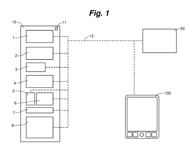
Figure 1 is a schematic illustration of a medical system that includes a
plurality of
medical devices 1-8, a computing or information system 50, and a portable
device 100. A
quantity of eight medical devices 1-8 is illustrated, but the number depicted
is arbitrary. The
systems and methods of the present disclosure may include and be practiced
with any suitable
number of medical devices, including only a single device. The dissimilar
shapes of the boxes
schematically representing medical devices 1-8 may suggest a heterogeneous
collection of
7
CA 02974080 2017-07-17
WO 2016/118330
PCT/US2016/012481
devices, but the systems and methods of the present disclosure can include and
be practiced with
any suitable combination of similar and dissimilar devices. In some examples,
some or all of
medical devices 1-8 are infusion pumps.
Medical devices 1-8 can be communicatively connected, via any appropriate
communication infrastructure(s) 12, to each other, to a computing or other
information system
50, and/or to portable device 100, in any appropriate combination(s) and
manner. The dashed
lines representing communication infrastructure(s) 12 of Figure 1 are merely
schematic and
should not necessarily be interpreted as limiting the communication
infrastructure(s) of the
present disclosure to any particular communication infrastructure topology,
technology, layers,
protocols, or any other aspect(s) of how communication can be implemented.
Furthermore,
illustrated connections (via the dashed lines representing communication
infrastructure(s) 12)
should not necessarily be interpreted as being alike between all devices and
systems, and should
not necessarily be assumed to be bidirectional. For example, medical devices 1-
8 could each be
communicatively connected to information system 50 via a wired connection
(such as Ethernet
or any other suitable protocol), an unwired connection (such as WiFi or any
other suitable
protocol), or both, whereas portable device 100 could be connected to
information system 50
and/or any of medical devices 1-8 via a wireless connection only. Any
appropriate
communication devices such as routers or repeaters can be employed in
communication
infrastructure(s) 12. Medical devices 1-8, portable device 100, and/or
information system 50 can
in some cases communicate via communication infrastructure devices such as
routers, but in
some embodiments can communicate directly with each other in peer-to-peer
modes. In some
embodiments, one or more of medical devices 1-8, portable device 100, and/or
information
system 50 can provide an infrastructure function, such as router. In some
arrangements,
communication infrastructure 12 can include any suitable combinations of peer-
to-peer and
network-based communication. In some embodiments, portable device 100 could
communicate
directly (for example, via a short-range radio frequency protocol such as
Bluetooth) with one of
medical devices 1-8, and the medical device could relay information from the
portable device to
information system 50. In some embodiments, portable device 100 could
communicate directly
(for example, via an ad-hoc WiFi connection) with information system 50, and
the information
system could relay information from the portable device to one or more of
medical devices 1-8.
In some embodiments, secure communication protocols, such as secure sockets
layer (SSL)
and/or transport layer security (TLS) can be employed for any of the various
communication
links between portable device 100, medical devices 1-8, and/or information
system 50 that may
be employed in systems or methods of the present disclosure. These are just
some examples. In
8
CA 02974080 2017-07-17
WO 2016/118330
PCT/US2016/012481
summary, the systems and methods of the present disclosure can include and be
implemented by
and with any communication infrastructure 12 suitable to realize the functions
of the systems and
methods, and should not be considered limited to any particular communication
architecture
unless specifically described as such.
Although information system 50 is depicted in Figure 1 as being external to
medical
device 1-8, it is to be appreciated and understood that such computing or
information system or
systems could reside in any location, such as externally or remotely in a
hospital's IT
infrastructure, or physically adjacent to or near the medical devices, or even
internally within one
or more of the devices (other than within one of the devices relative to which
the information
system 50 is described as being "external"). It is further to be appreciated
and understood that
information system 50 should not necessarily be considered to be limited to a
single physical
device (although in some embodiments it may be), but rather, any suitable
system or
arrangement of one or several components can be used to provide an information
processing
capability, such as one or more processes being executed by a networked system
of servers.
Medical devices 1-8 can be mounted, attached, and/or otherwise connected with
or to a
support structure 10, such as an equipment rack or pole, but this is not
necessary. The support
structure 10 can mechanically hold the medical devices in fixed physical
relationships with
respect to each other, and can, in some instances, provide other functions
such as electrical
power and/or communication cabling. In the latter case, the support structure
10 could thereby
provide a portion of communication infrastructure 12. In some embodiments the
support
structure 10 could include networking hardware (such as a router) with ports
for any or all
devices mounted thereto. Medical devices mounted to support structure 10 and
connected
(whether physically, as wired, or wirelessly) to the networking hardware
associated with the
support structure could be automatically associated with each other by way of
connection to the
networking hardware.
In some embodiments, one or more of the medical devices can be a portable
medical
device, configured to move with a patient (possibly even carried by a patient)
as the patient
moves about, and may be referred to as an "ambulatory" medical device. Some
example systems
of the present disclosure include only a single ambulatory medical device.
Figure 2 is a schematic illustration of portable device 100 of Figure 1, a
medical device
200 that can be any suitable medical device, such as any of medical devices 1-
8 of Figure 1, and
external information system 50. Portable device 100 can be any suitable
device. (Reference
numeral 100 is used throughout the figures of this application in reference to
a portable device,
and features of a portable device 100 described in relation to any particular
figure should not
9
CA 02974080 2017-07-17
WO 2016/118330
PCT/US2016/012481
necessarily be considered to be limited only to the configuration of that
figure. All illustrations
of portable device 100 in this application are merely schematic and should not
be considered
limiting. Differences in the appearance of portable device 100 between
drawings do not
necessarily represent substantive feature differences between embodiments of
portable devices.)
Portable device 100 can be a widely- and/or commercially-available multi-
purpose device such
as a smartphone, tablet or pad computer, personal digital assistant, or the
like. In other
embodiments, it can be a device specifically built for the purpose of being a
remote control
device for medical devices. Portable device 100 can include a user interface,
which can include
hardware controls 102 such as buttons and/or dials and the like, and a display
104. The user
interface can be configurable to present to a user virtual controls for a
medical device that is
paired with portable device 100. Display 104 can employ any suitable display
technology such as
liquid crystal display (LCD), organic light-emitting diode (OLED), electronic
paper display
(EPD), and the like. Display 104 can be a touchscreen display structured with
any suitable touch-
sensing technology, such as capacitive, resistive, and so on. When display 104
is configured as a
touchscreen display it can be suitable for providing a virtual control panel
for a medical device
with which the portable device 100 is paired. Such a virtual control panel can
be configured to
emulate the look and feel of the actual physical hardware of the medical
device, but is not
limited to such an emulation. A virtual control panel could provide
alternative or enhanced user
interface features as compared to the hardware of the medical device.
Portable device 100 can include an optical imaging device 106 (such as, but
not limited
to, a digital camera module), a wireless communication interface 108, a memory
110, and a
controller 112. The controller 112 can be operatively coupled to any or all of
the user interface
(for example, hardware controls 102 and/or display 104), the optical imaging
device 106, the
wireless communication interface 108, and the memory 110. In some embodiments,
components
of portable device 100 can be integrated: for example, memory 110 and
controller 112 could be
integrated and provided in or on the same physical component. In some
instances, portable
devices can include multiple controllers or processors (for example, either or
both of optical
imaging device 106 and wireless communication interface 108 could include a
purpose-specific
dedicated processor), and in the present disclosure, all
controllers/processors of portable device
may be collectively referred to as controller 112.
Portable device 100 can be configured and programmed to run application
software that
can provide remote control functionality for medical device 200. As used
throughout this
disclosure, the term "remote control" is intended to include any device
combinations that operate
at distances from each other, regardless of magnitudes of those distances
unless otherwise
CA 02974080 2017-07-17
WO 2016/118330
PCT/US2016/012481
specified. Such remote control application software can provide any suitable
degree of control of
medical device 200. In some embodiments, the control provided by a remote
control application
can be a reduced set of controls relative to the controls available to a user
interacting directly
with the medical device 200 via the device's built-in user interface. In some
other embodiments,
the degree of control provided by a remote control application can be
essentially the same as that
available to a user interacting directly with the medical device 200. In still
other embodiments,
the remote control application could provide a greater degree of control of
the medical device
200 than available to a user directly interfacing with the medical device.
Remote control application software for portable device 100 can, in some
embodiments,
be stored in memory 110 and executed by controller 112. In some other
embodiments,
information system 50 such as a server can run remote control software that
can be presented on
the user interface of portable device 100 via, for example, a web browser or
other client software
executed by controller 112 of the portable device.
Medical device 200 can include a built-in user interface that can include
hardware
controls 202 such as buttons or knobs and the like, and a display 204, which
may be based upon
or rely upon any suitable dynamic display technology such as the
aforementioned LCD, OLED,
EPD, and the like. Medical device 200 can include a communication interface
208, a memory
210, and a controller 212, which may include multiple controllers/processors.
The controller 212
can be operatively coupled to any or all, or any subgrouping of, the user
interface (for example,
hardware controls 202 and/or display 204), the communication interface 208,
and the memory
210. In some embodiments, components of portable device 200 can be integrated.
Medical device 200 can include any appropriate function-specific hardware 214
to
provide its intended functions as a medical device. In some examples, medical
device 200 can be
an infusion pump, and function-specific hardware 214 can include any or all of
a pump
mechanism, valves, motors, drive trains, gears, couplings, sensors,
application-specific
integrated circuits (ASICs), firmware, and any other accessories and
appropriate components. In
other examples, medical device 200 can be a patient-monitoring apparatus such
as a blood
pressure monitor; and function specific hardware 214 could include a pressure
cuff, hose, air
pump, sensors, ASICs, firmware, and any other appropriate components.
In systems and methods of the present disclosure, one or more codes 220 can be
displayed on display 204 of medical device 200 and imaged by optical imaging
device 106 of
portable device 100. "Imaged" by the optical imaging device 106 can mean
collecting (e.g.,
measuring and recording) sufficient information from the displayed code that
information
encoded in the code is able to be decoded, for example by the controller 112
of the portable
11
CA 02974080 2017-07-17
WO 2016/118330
PCT/US2016/012481
device. In this regard, display 204 of medical device 200 and optical imaging
device 106 of
portable device 100 can be specified, chosen, selected, tested, verified,
and/or validated to be
compatible with the function of propagating information optically from the
medical device to the
portable device. Display 204 can be capable of displaying a specified type of
code, such as a 2D
barcode, and optical imaging device 106 can be capable of imaging the code.
For example, the
display 204 can be large enough and have a sufficiently high spatial
resolution in order to be able
to display a type of code being employed, and the optical imaging device 106
can have optical
components and a sensor capable of resolving sufficient spatial detail to
record an image from
which the code can be decoded. In some embodiments, color could be used to
encode
information, in which case display 204 could be a color display, and optical
imaging device 106
could be a color camera, the display and camera being capable of displaying
and resolving,
respectively, colors being employed in the code. In some embodiments, other
optical attributes
of the display-imaging device pair may be exploited, such as contrast,
reflectivity, polarization,
and/or any other relevant characteristics.
Figure 3 is a flow diagram of an illustrative example of a method 300 for
pairing a
portable device with a medical device. The portable device can be the same as,
or similar to, for
example, portable device 100 of Figures 1 and 2, and the medical device can be
the same as, or
similar to, for example, medical device 200 of Figure 2, which could be the
same as, or similar to
any of medical devices 1-8 of Figure 1. Method 300 can be performed with a
medical system the
same as, or similar to the system of Figure 1, in any of the possible
compatible variations
contemplated in the present disclosure. Method 300 does not necessarily
require all elements
shown in the flow diagram of Figure 3. Method 300 also can include other
elements not shown
in Figure 3.
Method 300 can include, at 310, displaying an association code, which may be
represented by example code 220, on dynamic display 204 of a medical device
200. The
association code can be displayed in any suitable machine-readable code
format, or combination
of code formats, that can be displayed on display 204, read by optical imaging
device 106, and
decoded by controller 112 of portable device 100. Possible code formats that
can be used
include, but are not limited to, alphanumeric text, one-dimensional (1D)
barcodes such as
sequences of lines of varying thickness, two-dimensional (2D) barcodes such as
Quick Response
(QR) codes and other codes that can include matrices of squares, triangles,
hexagons and/or
other shapes, and other code formats that may currently exist or be introduced
in the future.
(Note that in some nomenclatures, what is referred-to in the present
disclosure as a "2D" barcode
may be referred to as a "3D" barcode, and what is referred-to in the present
disclosure as a "1D"
12
CA 02974080 2017-07-17
WO 2016/118330
PCT/US2016/012481
barcode may be referred to as a "2D" barcode.) Possible code formats could
include color to
encode information as well as density patterns, and could vary in appearance
over time (for
example, as a sequence of frames, a motion, a blinking pattern, an animation,
or as a movie,
etc.). In some examples, a code format that does not rely solely on characters
nor symbols of a
natural human language can be employed. In some examples, a code format that
does not include
any characters nor symbols of a natural human language can be employed. Code
formats can be
selected and used based on a variety of attributes, such as information
density, difficulty in
spoofing or otherwise compromising, robustness, ease of machine readability,
or any other
appropriate property.
The association code can include any suitable association information.
Association
information, as used herein, can refer to any information included in the
association code,
regardless of whether the information is particularly used for an
"association" purpose.
Association information can include medical device identification information,
which can be any
of a Unique Device Identifier (UDI), a manufacturer specific identification
code and/or serial
number, a communication network identification code or address (for example, a
media access
control (MAC) address), a hospital- or other organization-specific identifier,
or any other
suitable identification information. Association information can include
information about one or
more expected or preferred communication channel(s) or mode(s) for future
communication
(e.g., Bluetooth, via hospital infrastructure WiFi, via a specified server,
via a peer-to-peer WiFi
network, etc.)
Association information can include information identifying the model of the
medical
device and/or any suitable information (e.g., parameters) about the
configuration or status,
whether permanent or transient, of the medical device. Association information
can include date,
time, and location information, and the like. Association information can
include information
about a specific medical function that the medical device is configured or
intended to perform.
For example, in the case of an infusion pump, such information could include
information about
a particular infusion, such as a medicament, a dose or rate of dosage, syringe
parameters, an
amount of medicament available for delivery, an amount of medicament already
delivered, and
so on. Association information can include patient specific information such
as weight, height,
age, and so on, and can also include patient identification information.
The controller 212 of medical device 200 can be configured and programmed to
calculate, compile, and/or otherwise provide the association information, and
can be configured
and programmed to encode the association information into the association
code. In some
embodiments, another entity (such as information system 50) can contribute
association
13
CA 02974080 2017-07-17
WO 2016/118330
PCT/US2016/012481
information and/or the association code, in whole or in part, to medical
device 200 for display on
dynamic display 204.
Generally, an association code can include association information that is
time-sensitive,
transient, or perishable, and that can be verified in other parts of Method
300 before a pairing is
completed. The perishable nature of association codes can provide an important
security feature,
making them more difficult to spoof or otherwise compromise. In comparison, a
permanent or
infrequently-changing code might be vulnerable to being inappropriately
duplicated, with, for
example, a still image or other copy of the duplicated code being presented to
an optical imaging
device in place of a legitimate code actually displayed on dynamic display 204
of medical device
200.
Method 300 can include, at 320, determining whether the portable device 100 is
positioned relative to the medical device 200 within a predetermined range of
positioning
parameters. Aspects of this determination are discussed in further detail
elsewhere herein.
Determining that the portable device 100 is positioned relative to the medical
device 200 within
the predetermined range of positioning parameters can be referred-to herein as
a positive result.
Alternately, finding that the portable device 100 is not positioned relative
to the medical device
200 within the predetermined range of positioning parameters can be referred-
to herein as a
negative result.
At 330, the method can include optically reading the association code from the
dynamic
display 204 of medical device 200 with optical imaging device 106 of portable
device 100.
Optically reading a code can include imaging the code with sufficient image
quality (for
example, in terms of contrast, focus, distortion, etc.) such that information
encoded in the code
can be decoded. Optically reading a code can also include the decoding of the
information from
an image captured by the optical imaging device 106.
The determination 320 of whether the portable device 100 is positioned
relative to the
medical device 200 within a predetermined range of positioning parameters can
be performed as
a safety measure to try to ensure that the portable device is oriented or
aimed (or that the optical
imaging device 106 of portable device is aimed) at medical device 200, and not
at another
medical device that also may be displaying an association code, so that the
association code
optically read at 330 can be regarded with confidence as belonging to the
medical device with
which the user desires and intends to pair the portable device. The
predetermined range of
positioning parameters can be defined (as detailed further herein) to reduce
the possibility of the
portable device 100 optically reading (at 330) and/or processing a code other
than from a
medical device at which the portable device is deliberately aimed. In some
embodiments, having
14
CA 02974080 2017-07-17
WO 2016/118330
PCT/US2016/012481
a clear line-of-sight between optical imaging device 106 and an association
code may be
necessary for the portable device 100 to be positioned relative to the medical
device 200 within
the predetermined range of positioning parameters. However, in some
embodiments, the
existence of a clear line-of-sight may not by itself be sufficient for the
portable device 100 to be
positioned relative to the medical device 200 within the predetermined range
of positioning
parameters; in these embodiments, additional more stringent positioning
conditions may need to
be met in addition to having a clear line-of-sight.
In various embodiments of method 300, determining at 320 and optically reading
at 330
can be interrelated in various ways which may not necessarily be illustrated
in Figure 3. For
example, in some embodiments, the determination 320 can be performed before
the optical
reading 330, and in other embodiments, the optical reading 330 can be
performed before the
determination 320. As an example of the latter, the optical reading 330 can be
performed by the
portable device 100 with optical imaging device 106, and an image of the
association code
captured or recorded as part of the optically reading can be analyzed (as
discussed further herein)
as part of the determination 320. (If the determination 320 has a negative
result in such an
example, the information from the preceding optical reading 330 might then be
discarded.) As an
example of the former, if the determination 320 is performed first and
produces a positive result,
the method can proceed to optically reading at 330, but if the result is
negative, the optical
reading 330 can be delayed until another determination 330 yields a positive
result, or in some
cases, not performed. In some embodiments, optically reading the association
code at 330 is only
performed if it is determined at 320 that the portable device 100 is
positioned relative to the
medical device 200 within a predetermined range of positioning parameters. In
some
embodiments, a positive determination at 320 is a sufficient condition for
optically reading the
association code at 330, but is not necessarily a prerequisite. In some
embodiments,
determination of negative and/or positive results may be communicated to the
user of device
100, such as via a suitable message on display 104.
Another way in which determining at 320 and optically reading at 330 can be
interrelated
is illustrated as follows. In some embodiments, optically reading the
association code at 330 can
be considered to have two or more parts, including capturing an image of the
association code,
and then decoding the association code after the image has been captured. The
determination 320
could be performed by analysis of the image captured of the association code,
but the decoding
part of the optically reading 330 might not be performed subsequently if the
determination has a
negative result.
CA 02974080 2017-07-17
WO 2016/118330
PCT/US2016/012481
The determination 320 of whether the portable device 100 is positioned
relative to the
medical device 200 within a predetermined range of positioning parameters can
be performed by
any suitable processor. In some cases, the determination 320 can be performed
by the controller
112 of the portable device 100, for example, as a component of remote control
application
software being executed by the controller. In some embodiments, the
determination 320 can be
performed by the controller 212 of the medical device 200. In some
embodiments, the
determination 320 can be performed by a processor that is external to both the
portable device
100 and the medical device 200, such as computing or other information system
50 of Figure 1.
Some embodiments of method 300 can include communicating from the portable
device 100
information related to the association code read by the portable device, via a
wireless
communication mode. If the determination 320 is performed by a processor
external to portable
device 100, communicated information related to the association code read by
the portable
device can include information relevant to the determination, such as an image
of the association
code captured by the optical imaging device 106.
The predetermined range of positioning parameters can be defined, described,
or
specified in any appropriate way. Figures 4 and 5 schematically illustrate
some examples of
possible positioning parameters, or quantities related to positioning
parameters, that can be used.
Figure 4 is a schematic illustration of relative positioning between a medical
device 400, which
can be the same as, or similar to any of medical devices 1-8 and 200, and
portable device 100.
Medical device 400 is illustrated as displaying a code 420 on a dynamic
display 404. A line
segment/axis 430 can be defined, extending away from the code 420 generally
perpendicularly to
the display 404 and having a length D. A cylindrical volume of space 432 can
be defined about
line segment/axis 430, extending out to a radius R. Positioning parameters can
be defined, and
then a range of positioning parameters can be predetermined, within which the
portable device
100 or part of the portable device such as the optical imaging device 106 are
positioned within
the cylindrical volume 432. This is just one way to describe relative
positioning between a
portable device and a medical device. A variation on the parameters defining
cylindrical volume
432 could be to specify that the distance d of a line segment 436 between the
code 420 and the
optical imaging device 106 is less than a predetermined value, such as, for
example, 10 cm, 20
cm, 30cm, 40cm, 50 cm, 60 cm, or any other suitable value, when the portable
device 100 is
positioned relative to the medical device 400 within a predetermined range of
positioning
parameters. Such a distance parameter d could be applied in combination with a
radial distance r
between the optical imaging device and the line segment/axis 430 being within
a predetermined
range or value, or an angle 0 between line segments 436 and 430 being within a
predetermined
16
CA 02974080 2017-07-17
WO 2016/118330
PCT/US2016/012481
range or value. For example, r could be required to be within a predetermined
distance value
such as 3 cm, 5 cm, 7 cm, 10 cm, or any other suitable value, and/or 0 could
be required to be
within 20 degrees, 15 degrees, 10 degrees, 5 degrees, or any other suitable
value. Another
possible positioning parameter could be an angle co between an optical axis
434 of the optical
imaging device 106 and line segment 436, essentially quantifying how closely
the optical
imaging device is aimed toward the code on the display 404. Yet another
possible positioning
parameter could be an angle (not illustrated) quantifying rotation of the
portable device 100
relative to the code 420 and pump 400 about line segment 436; that is, how
closely are the
portable device and medical device both oriented "up," as opposed to
"sideways" or "upside
down" relative to each other. These are just some examples, and the
predetermined range of
positioning parameters can be defined, described, or specified in any
appropriate way. While
some of the parameters or variables illustrated in Figure 4 can be used to
specify, for example,
substantially cylindrical or conical volumes of space in which it may be
deemed necessary or
desirable for a portable device to be located, it is anticipated that any
arbitrarily-shaped
volume(s) of space could be defined with appropriate ranges of positioning
parameters. Any
suitable way of defining positioning parameters, and any suitable
predetermined range of
positioning parameters can be defined and used to reduce the possibility of
the portable device
100 optically reading (at 330) and/or processing a code other than from a
medical device at
which the portable device is deliberately aimed.
Determination of whether the portable device 100 is positioned relative to the
medical
device 200 within a predetermined range of positioning parameters can be
performed in any
suitable manner, and with any appropriate hardware. It is anticipated that the
determination can
be performed with the optical imaging device 106 of portable device 100, but
other
implementations are possible. Any suitable information measured or obtained by
optical imaging
device 106 can be used in the determination. For example, if optical imaging
device 106 has an
adjustable focus mechanism, information from the focus mechanism could be
used, such as a
range determination or estimation performed by the focus mechanism. In
addition or
alternatively, image analysis could be performed on one or more images
captured by the optical
imaging device 106. With a target having a known shape and size (for example,
a displayed
code, the medical device 200 as a whole, and/or some other fiducial marker(s)
of the medical
device), and knowledge of the properties of the optical imaging device 106,
analysis of an image
could yield a distance between the optical imaging device and the target, and
furthermore,
consideration of image properties such as perspective distortion could yield a
relative angular
relationship between the two.
17
CA 02974080 2017-07-17
WO 2016/118330
PCT/US2016/012481
In general, determining relative positioning can depend upon information about
the
capabilities of the specific hardware involved. For example, for an optical
imaging device that is
a camera, lens characteristics (for example, focal length(s), focus mechanism
calibration,
aberrations, etc.) and sensor characteristics (array size, resolution, etc.)
might be used. Given that
the systems and methods of the present disclosure are intended to be
practicable with a variety of
suitable hardware, the predetermined range of positioning parameters can be
defined
independently of any particular hardware capabilities of any particular
portable device.
Accordingly, it is anticipated that different portable devices having
different hardware can be
capable of determining whether they are positioned relative to medical devices
within the
predetermined range of positioning parameters, with the parameters being
identically described
for the different devices, and with the processor performing the determination
being capable of
interpreting the positioning parameters in light of the specific hardware
capabilities being used to
measure the positioning of the portable device relative to the medical device.
Method 300 can include at 340, pairing the portable device 100 and the medical
device
200, if predetermined conditions for entering paired communication are met.
Any suitable
conditions can be used to initiate entering paired communications. When
paired, the portable
device 100 and medical device 200 can be communicatively linked such that the
medical device
responds to commands sent from the portable device to the medical device.
Commands sent from
portable device 100 to medical device 200 can be specifically addressed only
to the medical
device. Any appropriate communication infrastructure 12 can be used for paired
communication.
A paired link between portable device 100 and medical device 200 can include a
secure and/or
encrypted communication link between the devices. A paired communication link
between
devices can include any other suitable characteristics that may be desired for
inter-device
communication.
In some embodiments, paired communication is entered at 340 only if, at 320,
it is
determined that the portable device 100 is positioned relative to the medical
device 200 within
the predetermined range of positioning parameters. However, this criterion is
not necessarily
required in all cases. In some other embodiments, paired communication can be
entered at 340
even if the determination at 320 does not find that the portable device 100 is
positioned relative
to the medical device 200 within the predetermined range of positioning
parameters. In some
applications, performing the determination at 320 may not be required. This
may be suitable in
applications where there is unlikely to be more than one medical device that
might be able to pair
with a portable device. One such application could be a home care scenario,
where a patient
18
CA 02974080 2017-07-17
WO 2016/118330
PCT/US2016/012481
receives therapy from a single medical device (such as, but not limited to, an
infusion pump) that
can be controlled by a paired portable device.
In some embodiments, paired communication is entered at 340 only if, at 330,
the
association code is optically read from the dynamic display 204 of the medical
device 200 with
the portable device 100. In some embodiments, paired communication is entered
at 340 only if
both (a) it is determined (at 320) that the portable device 100 is positioned
relative to the medical
device 200 within the predetermined range of positioning parameters, and (b)
the association
code is optically read from the dynamic display 204 of the medical device with
the portable
device.
In some embodiments, if the portable device is not positioned relative to the
medical
device within the predetermined range of positioning parameters, then the
method 300 includes
not pairing the portable device and the medical device, or preventing or
blocking the portable
device and medical device from being paired.
Method 300 can include preconditions for entering paired communication at 340
other
than a positive result from the determination at 320 and/or optically reading
the association code
at 330. The preconditions can include appropriateness for entering into paired
communication
and/or control, as defined in any appropriate way and as ascertained in any
suitable manner.
Appropriateness for entering into paired communication can be an attribute of
either or both of
the medical device 200 and portable device 100. As an example, a medical
device 200 that is an
infusion pump could be appropriately paired to a portable device 100 for
remote control from the
portable device in only some infusion applications, but not others. In another
example, a portable
device 100 could be subject to appropriateness criteria related to whether the
portable device is
executing other processes that could potentially interfere with the portable
device performing as
a paired remote control for medical device 200. Whether appropriateness
preconditions are met
could be determined by any suitable processor. In some embodiments, a user or
other agent
could manually specify appropriateness for pairing of a medical device 200, a
portable device
100, or any combination of medical device(s) and portable device(s).
Preconditions for entering paired communication at 340 can include any
suitable
preconditions relating to the association information of the association code
optically read at
330. Preconditions could include whether a date, time, and or location of
association information
are consistent with the same parameters of the portable device 100, or of
information system 50.
Preconditions could include whether association information relating to the
specific medical
function that the medical device is to perform and/or patient specific
information agree with the
same kind(s) of information already resident in the memory 110 of portable
device 100, and/or in
19
CA 02974080 2017-07-17
WO 2016/118330
PCT/US2016/012481
information system 50, which could be, for example, a hospital information
system. In some
embodiments, optical imaging device 106 could be used to read information from
objects such as
an identification wristband of a patient, a medicament container, and so on,
with verification of
such information potentially being used as a precondition for entering paired
communication
between the portable device 100 and medical device 200, and/or for other
confirmation relating
to operation of the medical device.
Preconditions for entering paired communication at 340 could include
consideration of
aspects of communications infrastructure 12, such as whether appropriately
secure and reliable
communication links are established between the portable device 100 and
medical device 200,
and possibly information system 50.
Pairing at 340 of Method 300 of the portable device 100 with the medical
device 200 can
be commanded by any suitable processor. A processor commanding or otherwise
initiating
pairing can be configured to determine whether predetermined conditions for
entering paired
communication have been met, and if so, it can issue commands to any or all of
portable device
100, medical device 200, and/or information system 50, that can result in
establishment of a
paired communication link between the portable device and the medical device.
In some embodiments, the controller 112 of the portable device 100 is
programmed and
configured, if the association code is read from the dynamic display 204 of
the medical device
200, to determine whether predetermined conditions for entering paired
communication with the
medical device have been met, including considering information related to the
association code.
If the predetermined conditions for entering paired communication with the
medical device 200
are determined to have been met, the controller 112 of the portable device can
be programmed
and configured to communicate, via the wireless communication interface 108, a
command to
the controller 212 of the medical device to pair with the portable device 100.
The controller 212
of the medical device 200 can be programmed and configured to pair with the
portable device
100 under the (communicated) command of the controller 112 of the portable
device 100.
Optionally, the controller 112 of portable device 100 could also communicate
with information
system 50 to, for example, inform the information system 50 of the pairing of
the portable device
with the medical device 200, or to command the information system 50 to act as
an intermediary
or other participant in the pairing. In some of these embodiments, commands or
other
communications from the controller 112 of the portable device 100 can include
information
related to the association code read by the optical imaging device 106.
In some embodiments, the controller 212 of the medical device 200 can be
programmed
and configured to pair with the portable device 100 after the controller of
the medical device has
CA 02974080 2017-07-17
WO 2016/118330
PCT/US2016/012481
determined that predetermined conditions for entering paired communication
with the portable
device have been met. Such a determination by the controller 212 of the
medical device 200 can
include consideration of information related to the association code
communicated by the
controller 112 of the portable device via its wireless communication interface
108 after having
been read by the optical imaging device 106. A determination by the controller
212 of the
medical device 200 of whether to pair the portable device with the medical
device can include
any relevant considerations pertinent to pairing discussed herein, including,
for example,
determining whether the portable device is positioned relative to the medical
device within a
predetermined range of positioning parameters, although this is not required;
the relative position
determination can be performed, in some cases, by the controller of the
portable device. A
determination by the controller 212 of the medical device 200 of whether to
pair can be made
alternatively to such a determination being made by the controller 112 of the
portable device
100. In some embodiments, a determination by the controller 212 of the medical
device 200 of
whether to pair the portable device with the medical device can be made in
addition to such a
determination being made by the controller 112 of the portable device 100. In
some
embodiments, both controllers 112 and 212 of the portable device 100 and
medical device 200
could be required to determine that predetermined conditions for entering
paired communication
with each other have been met before such a pairing would be entered.
An information system 50 external to the portable device 100 and medical
device 200 can
command pairing in some embodiments. The information system 50 can be any
suitable system,
residing in any suitable location. The information system 50 can include, for
example, an
electronic medical record ("EMR") system, an electronic medical administration
record
("EMAR") system, a Hospital Information System ("HIS"), a pairing server or a
pairing process
running on a server provided specifically to perform pairing-related computing
tasks, a general
purpose personal computer, or another appropriate computing system. In such an
embodiment
involving an external information system 50, the portable device 100 can read
an association
code from the dynamic display 204 of the medical device 200 with its optical
imaging device
106, and communicate, via its wireless communication interface 108,
information related to the
association code read by the optical imaging device. The information related
to the association
code can be any suitable information, taking any suitable form. In some
embodiments, the
related information can include, in decoded form, all or part of the
association information
encoded in the association code. In some embodiments, the related information
can include
information deriving or transformed from association information. In some
embodiments, the
21
CA 02974080 2017-07-17
WO 2016/118330
PCT/US2016/012481
related information can include an image of the association code captured by
the optical imaging
device 106.
The external information system 50 can be programmed and configured to receive
from
the portable device 100 information related to the association code read by
the optical imaging
device 106, and determine whether predetermined conditions for entering paired
communication
between the medical device 200 and the portable device have been met. If
predetermined
conditions for entering paired communication between the medical device 200
and the portable
device 100 are determined to have been met, information system 50 can be
programmed and
configured to communicate commands to the controller 212 of the medical device
and the
controller 112 of the portable device to pair. The determination by the
information system 50
whether predetermined conditions for entering paired communication between the
medical
device 200 and the portable device 100 have been met can include any relevant
considerations
discussed herein, including, for example, determining whether the portable
device is positioned
relative to the medical device within a predetermined range of positioning
parameters, although
this is not required; the relative position determination can be performed, in
some cases, by the
controller of the portable device. A determination by an external information
system 50 whether
to pair can be made alternatively or in addition to such a determination being
made by either or
both of the controller 112 of the portable device 100 and/or the controller
212 of the medical
device 200.
In some embodiments, determining whether predetermined conditions for entering
paired
communication have been met can be a shared task among multiple processors. As
an example,
in one scenario (1) a processor of a medical device could apply
appropriateness criteria to
determine whether the medical device is in a state in which pairing is
appropriate; (2) a processor
of a portable device could determine whether the portable device is positioned
relative to the
medical device within a predetermined range of positioning parameters; and (3)
a processor of an
external information system could consider the outcomes of the determinations
of (1) and (2), as
well as its own determinations of whether other predetermined conditions are
met, before the
processor of the external information system potentially issues commands to
initiate paired
communication between the portable device and the medical device.
In some embodiments, pairing the portable device and the medical device
includes
receiving confirmation from a user to make the pairing, but this is not
necessary in all
embodiments. Any suitable user confirmation protocol can be used. Some user
confirmation
protocols can include information displayed on either or both of medical
device 200 and portable
device 100. In some examples, displayed information on both medical device 200
and portable
22
CA 02974080 2017-07-17
WO 2016/118330
PCT/US2016/012481
device 100 could be coordinated to increase the likelihood that a user would
recognize that the
two devices are acting/communicating in a paired manner. A user confirmation
protocol could
include a required response from a user to the user interface either or both
of medical device 200
and portable device 100. Such a response or responses could include a touch,
an audible
response, a motion, or any other detectable action. In some examples,
receiving confirmation
from a user does not require physical contact with the medical device, as
might be desirable to
avoid contamination.
When paired, the portable device 100 can act as a remote control unit for the
medical
device 200 and can send commands to the medical device. At 350 of Method 300,
the medical
device 200 can execute a medical function in response to a command sent from
the portable
device 100.
After pairing at 340 of Method 300, portable device 100 and medical device 200
can
remain paired for any suitable duration of time. At 360 of Method 300, the
portable device 100
and medical device 200 can be de-paired. As used in this disclosure, the term
"de-pair" refers to
an action in which a paired communication link is paused, suspended,
terminated, or otherwise
stopped. De-pairing can be triggered by any suitable criteria. Some possible
de-pairing criteria
can include the completion of a medical procedure, such as a medicament
delivery by an
infusion pump. De-pairing can be manually commanded by a user. In some
examples, a medical
system can include one or more location systems configured and capable of
determining one or
more location, such as a location of portable device 100 and one or more of
medical devices 1-8
and/or 200. Location systems can use any suitable technology, such as global
positioning system
(GPS) and/or other satellite navigation systems, radio-frequency
identification (RFID), WiFi-
assisted location, inertial dead-reckoning, and so on. In some embodiment, if
the location of the
portable device 100 and/or medical device 200 meets one or more pre-determined
conditions, the
devices can be de-paired. De-pairing can be commanded by any suitable
processor, such as
controller 112 of portable device 100, controller 212 of medical device 200,
and/or information
system 50.
Following de-pairing, previously-paired portable device 100 and medical device
200 can
subsequently be re-paired to reestablish paired communication. In some
embodiments, re-pairing
devices that had been paired previously can be initiated or commanded after
conditions for re-
pairing have been satisfied. In some cases, such conditions for re-pairing can
differ from
preconditions for pairing that are to be satisfied for devices that do not
have a recent or relevant
history of having been paired, and could be less stringent conditions. In some
embodiments,
23
CA 02974080 2017-07-17
WO 2016/118330
PCT/US2016/012481
devices can be de-paired in a manner that requires a subsequent pairing to
satisfy preconditions
no less stringent than for a pairing of devices not previously paired.
Other methods for pairing a portable device with a medical device are
contemplated in
the present disclosure. Figure 5 is a flow diagram of another illustrative
example of a method
500 for pairing a portable device with a medical device. Method 500 can
include multiple
elements that are similar to or the same as corresponding elements of Method
300 of Figure 3.
Elements 510, 520, 530, 540, 550, and 560 of Method 500 can be substantially
the same as or
similar to elements 310, 320, 330, 340, 350, and 360 of Method 300, to the
extent that the
descriptions of the elements of Method 300 are not inconsistent with specific
descriptions of
Method 500.
At 502, Method 500 can include optically reading, with optical imaging device
106 of
portable device 100, an identification code that identifies medical device
200. The identification
code can be displayed in any suitable machine-readable code format, or
combination of code
formats, similarly as for the association code, and the discussion of possible
code formats
provided in relation to the association code generally applies to code formats
for the
identification code.
The identification code can include any suitable identification information.
Identification
information, as used herein, can refer to any information included in the
identification code,
regardless of whether the information is particularly used for an
"identification" purpose. The
identification information can include any suitable information that uniquely
references a
specific individual medical device, such as a Unique Device Identifier (UDI),
a manufacturer
specific identification code and/or serial number, a communication network
identification code
or address, a hospital- or other organization-specific identifier, or any
other suitable
identification information. The identification information of the
identification code can include
sufficient information to allow portable device 100 in possession of the
identification
information to communicate with a specific individual medical device
referenced by the
identification code. In some examples, this information can include a unique
network address of
the specific individual medical device that allows portable device 100 to
establish a
communicative connection over communication infrastructure 12 to the medical
device. In some
other examples, the identification information of the identification code can
include information
that, when presented by the portable device 100 to an external system such as
information
system 50, allows the information system to enable a communicative connection
between the
portable device and the specific medical device referenced by the
identification code. In one such
example, the identification information of the identification code includes
information that
24
CA 02974080 2017-07-17
WO 2016/118330
PCT/US2016/012481
identifies a specific individual medical device, but not a network address for
the medical device.
In this example, the information system 50 possesses the network address for
the medical device
and facilitates communication between portable device 100 and medical device
200 after
receiving identification information communicated by the portable device after
the portable
device read said identification information via the identification code.
The identification code that is optically read at 502 of Method 500 can be
displayed in
any suitable location. In some examples, the identification code is displayed
on the medical
device 200. In some instances, the identification code is displayed on dynamic
display 204 of
medical device 200. The identification code can, in some instances, include
less encoded
information than an association code, and accordingly, it can occupy a smaller
portion of the
display area of dynamic display 204 than an association code. In some
embodiments, the
identification code can be displayed on dynamic display 204 for a
substantially greater fraction
of time that medical device 200 is powered, as compared with a fraction of
time that an
association code might be displayed. In some embodiments, the identification
code can be
displayed on dynamic display 204 whenever the medical device is in a state in
which it can be
paired or a state in which it can commence pairing. In some embodiments, the
identification code
can be, substantially, permanently displayed on an enclosure, housing, or case
of medical device
200, as for example, being printed on a surface thereof In some embodiments,
the identification
code can be non-permanently affixed to a medical device, such as with an
adhesive sticker. In
some cases, the identification code can be provided spatially apart from a
medical device, such
as on a printed sheet or on a workstation display screen.
In some embodiments, optically reading the identification code at 502 can be
performed
in conjunction with determining whether the portable device 100 is positioned
relative to the
medical device 200 within a predetermined range of positioning parameters.
Such a
determination can be performed specifically relating to optically reading the
identification code
at 502, and independently from a determination (at 520) performed in
conjunction with reading
an association code (at 530). The same or different predetermined ranges of
positioning
parameters can be used for separate determinations. Similarly as with 320 and
330 of Method
300, optically reading the identification code at 502, or using the
information from such a
reading, can depend upon whether an associated positioning determination has a
positive or
negative result.
In some embodiments, a single determination (for example, at 520) of whether
portable
device 100 is positioned relative to medical device 200 within predetermined
parameters can be
performed in conjunction with both optically reading the identification code
at 502 and optically
CA 02974080 2017-07-17
WO 2016/118330
PCT/US2016/012481
reading the association barcode at 530. Such a single determination may be
appropriate or
acceptable if a time interval between the two readings is sufficiently small
that the relative
positions of the portable device 100 and medical device 200 are not likely to
change significantly
between readings.
At 506, Method 500 can include commanding the medical device 200 to display an
association code on dynamic display 204 of the medical device 200. In some
embodiments,
commanding at 506 is performed in response to reading the identification code
at 502, and such a
command can be issued by any appropriate device, including processor 112 of
the portable
device 100. In some examples, the portable device 100 can communicate
information related to
the identification code read by the portable device (for example, via a
wireless communication
mode), and a processor external to the portable device (for example, of
information system 50)
can receive the information related to the identification code and in
response, command the
medical device 200 to display the association code. In some embodiments, the
medical device
200 can be commanded at 506 to display an association code on dynamic display
204 in
response to events other than reading an identification code at 502. For
example, a user could
initiate a pairing by interacting in any suitable manner with the user
interface of either the
medical device 200 or the portable device 100, which could result in a command
to the medical
device to display an association code on dynamic display 204. In another
example, information
from a location system that portable device 100 is within a specified
proximity of medical device
200 could lead to a command to the medical device 200 to display an
association code.
After a command to display an association code is issued at 506, Method 500
can
proceed at 510 to displaying the association code on dynamic display 204 of
medical device 200.
As stated elsewhere, elements 510, 520, 530, 540, 550, and 560 of Method 500
can be
substantially the same as or similar to elements 310, 320, 330, 340, 350, and
360 of Method 300.
Multiple medical devices can be paired with a portable device with methods of
the
present disclosure. Variations on Methods 300 and 500 can include repeating
any of the elements
of the methods to pair a second or further medical device(s) with portable
device 100 such that
the second or further medical device(s) respond(s) to commands sent from the
portable device to
the device(s).
In some embodiments, members of a group of medical devices can be associated
with
each other before commencement of a pairing process. Such associations can be
defined or
established in any suitable manner, and information about such associations
can be stored or
maintained in any suitable repository, such as information system 50. In some
embodiments of
pairing methods, multiple medical devices that are associated prior to
commencement of a
26
CA 02974080 2017-07-17
WO 2016/118330
PCT/US2016/012481
pairing process can be paired to a portable device after an association code
is optically read from
a single one of the medical devices by the portable device. In some
embodiments, pairing of
multiple medical devices to a portable device might proceed after association
codes are read
from a subset or all of the associated multiple medical devices.
As described elsewhere in conjunction with Figure 1, in some examples multiple
medical
devices such as devices 1-8 can be automatically associated when mounted to an
equipment rack
or other support structure such as structure 10 and connected to networking
hardware of the
structure. In some of these scenarios, a variation on Method 500 can be
practiced to pair portable
device 100 with some or all of medical devices 1-8. Support structure 10 can
include an
identification code 11 including information identifying the support structure
and by extension,
any of medical devices 1-8 that are associated with the support structure (the
devices being
associated with the structure, for example, by virtue of being connected to
networking hardware
of the structure). Optically reading identification code 11 with portable
device 100 can trigger
any suitable processor (for example, controller 112 of portable device 100,
controller 212 of
medical device 200, information system 50, etc.) to proceed with a process to
pair any or all of
associated devices 1-8 to portable devices, as may be appropriate. Such a
variation on Method
500 could include displaying an association code on one or more of the medical
devices 1-8 to be
paired, with pairing being achieved after the association code(s) is/are read
and any other
predetermined conditions for entering pairing are met. In some variations,
only a single
association code need be read from one of medical devices 1-8 to pair a
plurality of devices to
portable device 100. In some variations, an association code is read from each
of the medical
devices 1-8 to be paired to portable device 100.
In some embodiments, more than one portable device can be paired or linked to
the same
medical device or devices. In such arrangements, information could be
synchronized such that
any of the multiple portable devices would display essentially the same
information with regard
to a linked medical device.
In some embodiments where multiple medical devices are paired with portable
device
100, methods of the present disclosure can include rendering on display 104 of
the portable
device a virtual representation of the paired medical devices that emulates
the real-world spatial
relationship between the medical devices. Figure 6 is a schematic
representation of portable
device 100 with a simulated virtual representation 602 of medical devices 1-8
of Figure 1 on
display 104, as well as a simulated virtual control panel 604. One of the
virtual medical devices
of virtual representation 602 is shown with hatched lines, indicating the
device to which virtual
control panel 604 corresponds. This is merely an example of possible user
interface features.
27
CA 02974080 2017-07-17
WO 2016/118330
PCT/US2016/012481
Information about the real-world spatial relationship between the medical
devices, to inform the
virtual representation of the devices, can be garnered in any suitable manner.
In some examples,
spatial information about medical device positioning could be manually entered
via a user
interface. In configurations where medical devices 1-8 are associated with
structure 10 by virtue
of being connected to networking hardware of the structure, information about
the real-world
spatial relationship between the medical devices could be inferred or
otherwise established from
the connections to the networking hardware (for example, particular hardwired
network ports
could be associated with specific physical locations of medical devices
relative to structure 10).
In some examples, images and/or other information collected by optical imaging
device 106
and/or other sensors could be interpreted to determine the relative positions
of medical devices.
In some embodiments, portable device 100 can display on display 104, in the
manner of a
camera viewfinder, real-time images being captured by optical imaging device
106 before and/or
while reading identification and/or association codes, and/or after one or
more pairings have
been established. Such a display could assist a user in comparing/verifying
what the optical
imaging device is imaging ("seeing") in relation to what the user can see of
the actual medical
device(s) with the user's own eyes. Such an electronic viewfinder display on
display 104 of the
portable device 100 can be artificially enhanced (for example, with outlining,
highlighting, or
other visual cues) to assist the user in recognizing a medical device of
interest (for example, a
device whose code is being targeted/read). In some examples, the user can
select a medical
device for further interaction from such a real-time electronic viewfinder
display, for example,
by touching the image of the device on a touch-screen display. Selecting a
medical device for
further interaction could be followed by, for example, the selected medical
device being
commanded to display an association code, or a virtual control panel for the
selected medical
device being activated.
This disclosure is to be understood to be not limited to the particular
examples described
herein, but rather should be understood to cover all aspects of the disclosure
and equivalents
thereof Various modifications, processes, and components, as well as numerous
structures to
which the disclosure can be applicable, will be readily apparent to those of
skill in the art upon
review of the instant specification.
28