Note: Descriptions are shown in the official language in which they were submitted.
- 1 -
FLIGHT CONTROL LAWS FOR AUTOMATIC HOVER HOLD
Technical Field
The present application relates generally to flight control systems, and more
particularly, to flight control laws for automatic hover hold.
Description of the Prior Art
Brownout or whiteout is a phenomenon where flight visibility is reduced due to
airborne particles from rotor downwash. During brownout, the pilot is unable
to see
nearby objects which are necessary to provide outside visual references in
order to
control the aircraft while hovering near the ground.
Because of brownout, the
degraded visual environment can cause the pilot to lose awareness, which can
lead to
an accident.
Brownout during helicopter landing and take-off operations in arid desert
terrain
has been responsible for more than 30 accidents in recent years. Intense,
blinding
dust clouds stirred up by the helicopter rotor downwash can cause significant
flight
safety risks from ground obstacle collisions and dynamic rollover due to
uneven
terrain.
In 2004, an emergency medical services (EMS) helicopter crashed into terrain
while maneuvering in reduced visibility at night. The pilot, flight paramedic,
patient, and
patient's mother were killed, and the flight nurse was seriously injured.
Witnesses
reported brownout conditions at the time of the accident.
Brownout crashes have claimed more helicopters in recent military operations
than all other threats combined. More than 20 cases due to brownout were
reported
during military activities in Iraq and Afghanistan. These mishaps resulted in
aircraft
damage and, in many cases, involved aircrew injury and death.
In 2001, a U.S. Marine Corps UH-1N inadvertently touched down during takeoff
while drifting to the right and rolled over. One member of the crew was
ejected and
the other three crewmen were able to exit prior to the aircraft being
destroyed by fire.
CA 2974171 2017-07-19
- 2 -
Also in 2001, a MH-60K Blackhawk search and rescue helicopter caused a
brownout during a night approach, obscuring the landing area. The aircraft
crashed in
a sand dune, resulting in two deaths and injuries to three others.
Brownout and whiteout conditions can be caused by sand storms, low wind-
shear interaction, and helicopter downwash with ground effect. In most cases,
the
brownout scenario is unavoidable. Flying into this kind of environment can be
very
challenging when encountering an unprepared landing site, obstacles in the
landing
zone or flight path, loss of the horizontal reference, instrument
malfunctions, windy
conditions, sensor errors, jammed actuators, or ground effect interactions.
Several new methods and devices to aid the pilot in brownout situations have
been introduced in recent years. These include site preparation such as a
suitable
landing mat, pilot training, synthetic vision systems also known as "see and
remember", upgraded horizontal situation indicator with accelerations cueing,
and
aerodynamics such as the "winged rotor".
Although the foregoing devices and methods represent great strides in aircraft
control, many shortcomings remain.
Summary
In accordance with a first broad aspect, there is provided a method for high
speed transition to hover for an aircraft.
The method comprises commanding a nose pitch attitude and a deceleration
rate with a longitudinal controller, activating a longitudinal aft beep while
continuing
to hold pitch attitude with the longitudinal controller, releasing an aft
longitudinal
controller to hold pitch attitude, automatically decelerating the aircraft at
a constant
rate, defining a first flight envelope having a first groundspeed threshold,
and
engaging a hover hold with a control law hover hold architecture as the
aircraft
enters the first flight envelope.
CA 2974171 2017-07-19
- 3 -
Brief Description of the Drawings
The novel features believed characteristic of the application are set forth in
the appended claims. However, the application itself, as well as a preferred
mode of
use, and further objectives and advantages thereof, will best be understood
with
reference to the following detailed description when read in conjunction with
the
accompanying drawings, wherein:
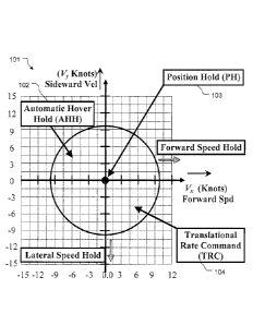
Figure 1 shows the automatic hover hold (AHH), translational rate command
(TRC) and position hold (PH) regions;
Figure 2 shows the simplified flight control law design with logic;
Figure 3 shows longitudinal loop design;
Figure 4 shows the longitudinal and lateral TRC beep scheduling;
Figure 5 shows lateral loop design with a separate lateral speed loop;
Figure 6 shows lateral loop design with an integrated lateral speed loop;
Figure 7 shows directional loop design;
Figure 8 shows vertical loop design;
Figure 9 shows the vertical beep scheduling with altitude;
Figure 10 shows the logic of AHH;
Figure 11 shows the logic of the PH; and
Figure 12 shows the architecture for the emergency hover hold mode;
While the control system of the present application is susceptible to various
modifications and alternative forms, specific embodiments thereof have been
shown
by way of example in the drawings and are herein described in detail. It
should be
understood, however, that the description herein of specific embodiments is
not
intended to limit the invention to the particular embodiment disclosed, but on
the
contrary, the intention is to cover all modifications, equivalents, and
alternatives
falling within the spirit and scope of the process of the present application
as defined
by the appended claims.
CA 2974171 2017-07-19
- 4 -
Description of the Preferred Embodiment
The present application is directed to existing aircraft sensors, actuators,
and
control laws to help the pilot overcome brownout or degraded visual
environment
(DVE) flight. The innovative control law architecture, with advanced concepts
to
stabilize the aircraft, allows the pilot to maneuver at low speed with minimal
compensation and workload. It has been demonstrated in previous flight testing
that
even with wind conditions as high as 30-35 knots, aircraft performance will
not
degrade with the advanced control laws (CLAWS) of the present application.
More
than 80 hours of flight testing have been conducted to prove the robustness of
these
CLAWS. Furthermore, it has been shown that even non-pilots can handle the
aircraft utilizing the CLAWS of the present application.
Referring now to Figure 1 in the drawings, various flight envelopes are
depicted in chart 101. Automatic hover hold (AHH) 102 will engage if the pilot
releases both the longitudinal and lateral controls when groundspeed is less
than 10
knots in the preferred embodiment. This AHH threshold can be adjusted based on
mission requirements. Position hold (PH) 103 will engage below 1 knot
groundspeed if both the longitudinal and lateral controls are released. Once
AHH
has been engaged, if the pilot moves the longitudinal or lateral control out
of the zero
force detent position, then the CLAWS will enter the translational rate
command
(TRC) mode 104. In this region, the aircraft will fly at a groundspeed
proportional to
the amount of control displacement. The TRC mode will disengage if the TRC or
actual groundspeed exceeds the AHH threshold. At that time, the CLAWS can
enter
either an attitude command or rate command mode, depending on mission
requirements.
This invention is comprised of four functions. The first function is AHH as
shown in the AHH and TRC mode regions of Figure 1. The second function is PH
as
shown in the PH region of Figure 1. The third function is called high speed
transition
to hover (HSTH). The fourth function is called emergency hover hold (EHH).
These
four functions are applicable to both fly-by-wire, as well as traditional
mechanical
flight control systems with partial authority flight control actuators.
CA 2974171 2017-07-19
- 5 -
The AHH mode will smoothly and automatically engage as the rotorcraft
decelerates from a higher ground speed to within the default AHH speed range.
The
PH mode will automatically engage when the ground speed is lower than 1 knot.
PH
will disengage whenever the pilot displaces the longitudinal or lateral
controller. If
longitudinal or lateral control displacement is less than or equal to 1.0
inch, the TRC
mode will be active. If controller displacement is more than 1.0 inch, then
the
attitude or rate command mode will engage. Additionally, if the stick is
released to
the detent position with groundspeed below 10 knots, the aircraft will
automatically
enter a hover. Once groundspeed is below 1 knot, the PH mode will be engaged
to
hold the new hover position.
For the HSTH function, the pilot can slow down by moving the stick aft and
then using aft beep to trim the aircraft at a higher pitch angle, for example
15
degrees. The aircraft will decelerate at a constant rate and then
automatically hover
when groundspeed is lower than 10 knots. The initial pitch angle setting will
determine the deceleration rate of the aircraft. A higher initial pitch angle
will result
in a quicker deceleration.
The EHH function can be engaged when the aircraft meets one or more of the
following emergency conditions: if the pilot loses consciousness (i.e. a heart
attack
or battle injuries as detected by a pilot pulse detector or eye contact device
installed
in the cockpit); if the pilot feels the need to release the control of the
aircraft to the
flight control computer in scenarios such as brownout or DVE; if the EHH
switch
installed in the cockpit is activated; or if an out of control condition is
caused by
certain equipment, device, or sensor failures.
Auto-land of the aircraft can be implemented by merging the EHH mode with
an automatic descent to touchdown. However, if the auto-land is flown to an
uncharted landing zone, it may require assistance from a synthetic visual
system or
field operator to avoid any ground objects during the final landing approach.
The flight control laws described above require several control loops, which
are based on their corresponding axes:
CA 2974171 2017-07-19
- 6 -
1) In the longitudinal axis:
= Longitudinal rate command attitude hold (RCAH) ¨ Long2q,
= Longitudinal attitude command attitude hold (ACAH) ¨ Long2Theta, and
= Forward speed hold (FSH) and TRC ¨ Long2Vx.
2) In the lateral axis:
= Lateral rate command attitude hold (RCAH) ¨ Lat2p,
= Lateral attitude command attitude hold (ACAH) ¨ Lat2Phi, and
= Lateral speed hold (LSH) and TRC ¨ lat2Vy.
3) In the directional axis:
= Yaw rate command (YRC) ¨Ped2r, and
= Heading hold (HH) - Ped2Psi.
4) In the vertical axis:
= Radar Altitude Hold (RAH) ¨ Coll2Alt, and
= Vertical Speed Hold (VSH) ¨ Coll2VS.
Note that RCAH is the first loop in each of the longitudinal, lateral, and
directional axes. To stabilize these loops, the six degrees of freedom flight
dynamics
are decoupled based on the aircraft flight characteristics. Individual
decoupling of
each axis improves aircraft stability.
In AHH/TRC region, the aircraft will use the following controls in each loop:
1) Longitudinal: Long2Vx,
2) Lateral: Lat2Vy,
3) Directional: Ped2Psi, and
4) Vertical: Coll2Alt.
With the correct guidance arrangement and control input architecture, the
CLAWS presented in this application have made switchless automatic hover hold
effective and smooth.
CA 2974171 2017-07-19
- 7 -
Detailed Loop Design
The functions of the automatic hover hold invention described in this patent
application reside in the advanced CLAWS. The architecture of each individual
loop
design is not the same as conventional CLAWS. Individual guidance loops have
been designed to provide carefree, single axis maneuverability in the various
flight
regimes. In this present application, the emphasis is on:
= How to bring the aircraft back to hover mode,
= How to maneuver around the hover regime,
= How to transition from the AHH region to attitude or rate command
mode, and then to speed hold mode, and
= How to quickly transition the aircraft back to hover in an emergency.
To accomplish the functions presented in this application (AHH, TRC, PH,
HSTH, and EHH), the individual axes of control loops are discussed below. It
should
be noted that both fly-by-wire and traditional mechanical flight control
systems with
partial authority control actuators can achieve or perform these functions.
Simplified Flight Control Laws Descriptions
General flight control law architecture 201 is illustrated in Figure 2. For
helicopters, the longitudinal controller is utilized to control the aircraft
pitch attitude by
actuating the swashplate to create a forward or aft tilting of the rotor tip
path plane.
With sensors and logic integrated into the flight control laws, the
longitudinal axis can
be used to control pitch rate, pitch angle, and forward / aft speed.
For helicopters, the lateral controller is utilized to control the aircraft
roll
attitude by actuating the swashplate to create a lateral tilting of the rotor
tip path
plane. The lateral axis can be employed to control roll rate, bank attitude,
and lateral
speed, with sensors and logic integrated into flight control laws.
For conventional helicopters, the directional controller is utilized to
control the
aircraft heading by commanding tail rotor blade pitch angle. With sensors and
logic
CA 2974171 2017-07-19
- 8 -
integrated into flight control laws, the directional axis can be used to
control yaw rate
and heading at low speed
Finally, for a conventional helicopter, the vertical controller is utilized to
control
the aircraft altitude by commanding the main rotor collective blade pitch
angle. With
sensors and logic integrated into flight control laws, the vertical axis can
be used to
control vertical speed and altitude.
In order to optimize the performance of the automatic hover hold CLAWS,
methodologies to decouple and stabilize each aircraft axis are combined with
the
logic integration shown in Figure 2. Therefore, the longitudinal 203, lateral
205,
directional 207, and vertical 209 axes can be designed separately with little
inter axis
coupling.
Simplified Longitudinal Control Law Loops
The longitudinal loop design 301 is shown in Figure 3. The mode switching
logic for the longitudinal CLAW design 301 is defined as Mode Logic 211 shown
in
Figure 2. Arrangement of these longitudinal control loops is based on the
nature of
flight dynamics. In the longitudinal axis, the pitch rate is part of the short
period
mode, which acts quickly in the flight dynamics. Pitch attitude and
longitudinal speed
variables form the Phugoid mode of the longitudinal motion, which is a slow
motion
of the longitudinal axis. The pitch rate is preferably the first loop in the
control laws
since it is the fastest longitudinal state. By controlling pitch rate, pitch
attitude can be
added as the second loop. With pitch attitude stabilized and controlled, FSH
can be
added as the third loop.
CLAW logic will automatically initialize and engage the FSH loop 303, also
called Long2Vx, when the longitudinal controller is returned to the detent
position
and groundspeed is outside of the AHH region as shown in Figure 1. When the
longitudinal stick is out of detent, the longitudinal axis can be controlled
by either the
pitch attitude (Long2Theta) 305 or the pitch rate (Long2q) loop 307. These
functions
are called position command and or rate command, respectively. Similarly, the
longitudinal beep commands can be integrated into all three loops.
CA 2974171 2017-07-19
- 9 -
The steady state attitude search method is employed during initialization of
the FSH loop to make it more robust. The FSH function will be able to
stabilize more
quickly at any ground speed or airspeed by initializing to the approximate
pitch
attitude required to hold that speed.
The longitudinal control input loop 301 shown in Figure 3 is employed to
convert the pilot input from the longitudinal controller to the associated
command
format depending on which loop is in use. The associated command inputs from
the
pilot are converted in Tables 1 and 2.
Longitudinal speed beep 401 during flight in the AHH/TRC region is shown in
Figure 4. The TRC mode longitudinal beep function is gain scheduled with
respect
to the altitude above ground level (AGL). When altitude is lower than 10 feet,
the
speed beep is 1 knot. The groundspeed for longitudinal beep increases
proportionally from 1 to 5 knots as altitude AGL increases from 10 to 50 feet.
The
maximum longitudinal beep speed of 5 knots occurs when altitude AGL is at or
above 50 feet.
The innovation of the control input design provides the following advanced
benefits: the ability of the pilot to precisely control angle rate, attitude
position, or
translational rate; easy adjustment of control sensitivity to match design
guidelines or
make adjustments during flight test; the ability of the pilot to use the beep
command
switch to fine tune attitude, speed, or position; the ability of the pilot to
seamlessly
transition from one mode to another during each maneuver; and the ability of
the
pilot to fly the aircraft with increased agility.
Simplified Lateral Control Law Loops
The lateral loop design is shown in Figures 5 and 6. The mode switching
logic of the lateral control law design is defined as Mode Logic 211 shown in
Figure
2. There are two lateral loop designs for TRC mode. Lateral loop 501 is
defined in
Figure 5 and the other lateral loop design 601 is defined in Figure 6. The
difference
between loop 501 and loop 601 is Lat2Vy loop 503. Since lateral speed in
flight
dynamics can be considered a fast mode for an aircraft during slow speed or
CA 2974171 2017-07-19
- 10 -
hovering flight, Lat2Vy does not have to feed the Lat2Phi loop 505. The
arrangement of the lateral control loop, as shown in Figure 5, is based on the
nature
of the flight dynamics. In the lateral axis, the roll rate and lateral
velocity variables
are part of the rolling mode, which acts rapidly in flight dynamics. The roll
attitude
and yaw rate variables form the Dutch roll and spiral modes for lateral
motion. The
roll attitude and yaw rate variables are considered a slow motion of the
lateral axis.
Since the fastest lateral state can be either the roll rate or lateral
velocity, the lateral
loop design is different from the longitudinal axis. During low speed flight,
the fastest
lateral state of the aircraft developed from the rolling mode is either
lateral velocity or
roll rate. Therefore, in the present application, the lateral velocity loop
can stand-
alone for TRC maneuvering without going through the roll angle (Lat2phi) or
roll rate
(Lat2p) loops. LSH is improved and PH will precisely hold the aircraft's spot
over the
ground even under high wind conditions. For this reason, there are two first
loops in
the lateral control laws shown in Figure 5. One is for the LSH loop 503,
defined as
Lat2Vy, and the other is the roll rate control loop 507, defined as Lat2p.
With roll
rate under control, bank attitude can be added as the second loop. The fader
switch
509 between the Lat2Vy and Lat2p loops is added to smooth the transition
between
these two loops.
Figure 6 shows a different arrangement for Lat2Vy loop. In this embodiment,
the Lat2Vy loop feeds the Lat2Phi loop. This design is similar to that of the
longitudinal axis by assuming that the LSH loop is slow and is controlled by
the roll
angle of the aircraft. The bandwidth of this mode is lower than the Figure 5
design.
However, both designs are reserved in the present application. Furthermore,
both
LSH designs have been successfully demonstrated in flight testing.
CLAW logic will automatically initialize and engage the LSH loop 503, also
called Lat2Vy, when the lateral controller is returned to the detent position
and
groundspeed is outside of the AHH region as shown in Figure 1. When the
lateral
controller is out of detent, the aircraft's lateral axis can be controlled by
either the roll
attitude (Lat2Phi) or the roll rate (Lat2p) loop. These functions are called
position
command or rate command, respectively. Similarly, lateral beep commands can be
integrated into all three loops.
CA 2974171 2017-07-19
- 11 -
Like FSH, the steady state attitude search method is employed during
initialization of the LSH loop to make it more robust. The LSH function will
be able to
stabilize more quickly at any ground speed by initializing to the approximate
bank
angle required to hold that speed.
The lateral control input loops shown in Figure 5 and 6 are employed to
convert the pilot input from the lateral controller to associated command
formats
depending on which loop is in use. The associated command inputs from the
pilot
are converted in Tables 3 and 4.
The lateral speed beep in TRC mode is shown in Figure 4. Like the
longitudinal axis, the TRC mode lateral speed beep function is gain scheduled
with
respect to the altitude AGL. When altitude is lower than 10 feet, the speed
beep is 1
knot. The groundspeed for lateral beep increases proportionally from 1 to 5
knots as
altitude AGL increases from 10 to 50 feet. The maximum lateral speed beep of 5
knots per second in TRC mode occurs when altitude AGL is at or above 50 feet.
Simplified Directional Control Law Loops
The directional loop design 701 is shown in Figure 7. The mode switching
logic of directional control law design is defined as Mode Logic 211 shown in
Figure
2.
The preferred embodiment assumes that the yaw rate is the fastest directional
state. Design 701 further includes a HH loop 703 (Ped2Psi), outside of the YRC
loop 705 (Ped2r). When in the AHH region, the directional axis is designed to
control heading through the spiral mode.
In the preferred embodiment, YRC is the first loop for the directional control
laws. The HH loop will be re-engaged automatically during flight in the AHH
region
whenever the directional controller is in detent.
The directional control input loop 707 shown in Figure 7 is employed to
convert the pilot input from the directional controller to the associated
command
formats depending on which loop is in use. The associated command inputs from
the pilot are converted in Tables 5 and 6.
CA 2974171 2017-07-19
- 12 -
The innovation of the directional control input design provides the following
advanced benefits: the ability of the pilot to precisely control yaw rate and
heading;
easy adjustment of control sensitivity to match design guidelines or make
adjustments during flight test; the ability of the pilot to use the beep
command switch
to fine tune heading; the ability of the pilot to seamlessly transition from
one mode to
another during each maneuver; and the ability of the pilot to fly the aircraft
in the
directional axis with increased agility.
Simplified Vertical Control Laws Loops
The vertical loop design 801 is shown in Figure 8. The mode switching logic
of the vertical control law design is defined as Mode Logic 211 shown in
Figure 2. In
the preferred embodiment, the first vertical loop is VSH 803, which is defined
as
Coll2Hdot. The second loop is AH 805, defined as Coll2Alt. During low speed
and
hover flight conditions, the vertical control laws will hold altitude AGL when
the
vertical controller is in detent. When the controller is out of detent or if
the vertical
beep is commanded, the control laws will hold a vertical speed.
The collective control input loop 807 is shown in Figure 8 and is utilized to
convert the pilot input from the vertical controller to the associated command
formats
depending on which loop is in use. Tables 7 and 8 show the associated vertical
command inputs from the pilot.
Vertical beep during flight in the AHH/TRC region is shown in Figure 9. The
vertical beep function is gain scheduled with respect to the altitude AGL.
When AGL
altitude is lower than 20 feet, the beep rate is 2 feet per second. The
vertical beep
increases proportionally from 2 feet per second to 10 feet per second as
altitude
AGL increases from 20 to 100 feet. The maximum vertical beep of 10 feet per
second occurs when altitude AGL is at or above 100 feet. The vertical beep
rate
also ramps up over time. For example, if the pilot holds the altitude beep
switch for
one second when higher than 100 feet AGL, the vertical beep will reach 2 feet
per
second. If the pilot holds the switch for 5 seconds or longer, the vertical
beep will
reach a steady state rate of 10 feet per second.
CA 2974171 2017-07-19
- 13 -
LOGIC DESIGN
One of the main objectives for the AHH function is to capture the hover state
following an aircraft deceleration. This
function will greatly reduce the pilot's
workload especially in a degraded visual environment.
The second objective is to effectively hold the aircraft position following
the
hover capture. The current invention will accurately hold hover position even
while
turning in strong, gusty winds with the pilot's hands off of the controls.
The third objective is to enable the pilot to have carefree controlled flight
in
any condition. When all controls are in detent positions, the aircraft will
automatically
stabilize and fly in its associated modes.
The fourth objective is to smoothly transition through the different modes.
For
example, the advanced CLAWS allow for a smooth transition from TRC mode to
attitude command mode, and then finally to speed hold mode. The difference
between the two commands can cause a jump in the control input. However,
initialization logic is used to ensure transient-free switching from one mode
to
another.
The fifth objective is to provide HSTH, where the pilot can trim the aircraft
to
automatically capture hover from a high speed by using the longitudinal beep
to set a
pitch attitude for steady deceleration.
The sixth objective is to transition the aircraft into EHH mode during an
emergency situation. Usually, the EHH mode will not trigger when the pilot is
in
control.
Automatic Hover Hold (AHH) Mode
The logic 1001 of achieving the AHH function 1003 is shown in Figure 10.
The factors which determine if the AHH function is active (AHH On) include
total
ground speed, commanded groundspeed (Vx_Cmd or Vy_Cmd), and controller
detent status. The AHH logic will set the latch 1005 when both the
longitudinal and
lateral controllers are returned to the detent position, as long as the total
CA 2974171 2017-07-19
- 14 -
groundspeed is below the AHH threshold. This value can be set according to
mission requirements. In the preferred embodiment, the AHH threshold was set
to
knots. Once in the AHH mode, the aircraft will automatically enter a stable
hover
with the controller in detent. With the controller out of detent, the aircraft
will move at
5 a translational rate in the direction of and in proportion to the
displacement of the
longitudinal and lateral controllers. The AHH logic latch will reset, thus
deactivating
AHH, when either the total actual groundspeed or commanded groundspeed
exceeds the AHH threshold.
Longitudinal and lateral beeps in AHH mode are also reserved for the present
10 application. When the aircraft is in AHH mode, the TRC from longitudinal
and lateral
beep is scheduled with altitude AGL as shown is Figure 4. This new innovation
enables the pilot to fine tune the aircraft's hover position. In
the preferred
embodiment, the TRC beep is increased proportionally by 1 knot for each 10
feet
increase in altitude from 10 to 50 feet. This TRC beep schedule can be
adjusted
based on mission requirements.
When in the AHH mode, the longitudinal and lateral TRC response is first-
order and symmetrical. This makes translational movement from a stable hover
very
easy and intuitive, since the pilot just has to displace the controller in the
desired
direction of movement. In the preferred embodiment, the first 0.1-0.2 inch of
aircraft
stick movement is used to determine whether the stick is in the detent
position.
Furthermore, each 0.1 inch of stick displacement above the detent position
will result
in an additional 1 knot of commanded translational rate. With the AHH
threshold set
to 10 knots in the preferred embodiment, the total range for TRC is 1.0 inch
above
the detent position. Based on mission requirements, the TRC proportion of
controller
displacement to translational rate can be adjusted. For example, if each 0.1
inch is
driving 1.5 knots, the AHH region can be increased to 15 knots, instead of 10
knots
as shown in Figure 1. Similarly, the total controller displacement for the AHH
threshold can be adjusted. For example, if the total desired TRC speed is 6
knots,
then TRC will be engaged for up to 0.6 inch instead of 1.0 inch. The design of
TRC
mode is object-oriented (flexible flight characteristics) based on
implementation and
application.
CA 2974171 2017-07-19
- 15 -
Position Hold (PH) Mode
The PH logic 1101 is shown in Figure 11. The latch logic 1103 will be set and
PH 1105 engaged when groundspeed drops below the PH threshold, as long as the
longitudinal and lateral controllers are in detent and the longitudinal and
lateral beep
switches are not actuated. In the preferred embodiment, the PH threshold is
set to 1
knot of groundspeed. This
threshold can be adjusted based on mission
requirements. If the vertical and directional controllers are also released,
then the
advanced CLAWS will also automatically hold altitude AGL and heading steady.
In
the PH mode, the control laws will automatically hold the position over the
ground,
altitude AGL, and heading by engaging the following control loops:
= Longitudinal: Long2X, see box 309 of Figure 3,
= Lateral: Lat2Y, see box 511 of Figure 5 and box
609 of Figure 6,
= Directional: Ped2Psi, see box 703 of Figure 7, and
= Vertical: Coll2Alt, see box 805 of Figure 8.
The GPS position over the ground is captured by initializing the Long2X and
Lat2Y loops when latch conditions shown in Figure 11 are met. With PH engaged,
the captured position will be tightly held even in the presence of
disturbances due to
gusty winds or control inputs in the directional or vertical axes. If the
aircraft drifts off
from the captured position, the PH mode will make corrections to bring it
back.
The latch logic shown in Figure 11 will be reset when the longitudinal or
lateral
controllers are moved out of detent or if either the longitudinal or lateral
beeps are
activated.
High Speed Transition to Hover (HSTH)
When the aircraft is flying at a higher airspeed, the pilot can accomplish the
following steps to trim the aircraft to automatically decelerate to a hover
while in the
ACAH mode:
1) Use
the longitudinal controller to command a nose up pitch attitude and
deceleration rate.
CA 2974171 2017-07-19
- 16 -
2) Activate the longitudinal aft beep while continuing to hold pitch
attitude
with the longitudinal controller. As the pitch reference is adjusted with the
beep, the pilot will need to release aft longitudinal controller to hold pitch
attitude. When the pitch reference matches the held pitch attitude, the
longitudinal controller will be back in detent and the longitudinal CLAWS
will be in attitude hold.
3) The aircraft will decelerate at a constant rate until ground speed is
less
than the AHH threshold, at which point the AHH mode will automatically
engage and pull the aircraft into a hover.
4) The pilot can
adjust the deceleration rate by changing pitch with the
longitudinal beep. Furthermore, the HSTH can be stopped by moving the
longitudinal controller out of detent.
If the pilot moves the longitudinal controller aft out of detent while in
speed
hold at higher speeds and then releases it back to the detent position, then
HSTH
will not take place since speed hold will be re-engaged. If the pilot moves
the
longitudinal controller aft and holds it out of detent, the aircraft will fly
in attitude
command mode and will not enter AHH when passing the AHH threshold.
In order to hold a steady deceleration during HSTH, the steady state trim
method is applied. Once the pitch attitude is set with the longitudinal
controller in
detent, the control laws will enter the attitude hold mode. Initially, when
the
longitudinal controller is returned to detent, the control laws will capture
the
difference between the reference pitch attitude and the steady state trim
pitch
attitude for the current airspeed. This attitude difference is then added to
the steady
state trim attitude so that as the aircraft decelerates, the reference pitch
attitude will
be continually adjusted to hold a constant deceleration. The attitude hold
mode will
also work in this same manner to hold a constant acceleration if pitch is
trimmed
below the steady state trim attitude with the longitudinal controller in
detent.
CA 2974171 2017-07-19
- 17 -
Emergency Hover Hold (EHH)
The EHH mode can be included as an optional kit based on mission
requirements. This mode will be engaged in the following scenarios:
1) If the pilot loses consciousness, possibly due to a heart attack or
battle
injuries. This could be detected by biometric feedback (i.e. pulse or eye
contact detection) or by monitoring the pilot's control inputs.
2) If the pilot needs to release aircraft control to the flight control
computer due to
inadvertently encountering DVE, such as brownout. In this case, the pilot
could activate a cockpit switch to manually enter the EHH mode.
3) If equipment,
device, and/or sensor failures are detected which make it
impossible for the pilot to control the aircraft.
Figure 12 shows how the EHH Logic 1201 will determine whether to use the
pilot's control inputs or the EHH pseudo control inputs to control the
aircraft. Inputs
into the EHH logic block include the pilot's control inputs, the feedback of
the aircraft
state, biometric measures of the pilot's consciousness, the cockpit EHH
switch, and
an input from the flight control redundancy management system which signals
that
control system failures are preventing the pilot from controlling the
aircraft.
The EHH logic will monitor the pilot's control inputs and aircraft state to
detect
if the pilot has lost consciousness. Switching the CLAW input from man to
unmanned flight could be commanded under the following scenarios:
1) When
the pilot is unconscious, the controls may be inadvertently moved
beyond reasonable limits based on flight conditions. In this case, if the
pilot does not make a correction within a certain period, the control laws
will enter EHH.
2) If the pilot
moves the control stick and subsequently becomes unconscious
or experiences spatial disorientation, the aircraft may enter an unusual
attitude from which recovery before ground impact is not possible. If the
pilot does not make a correction before exceeding reasonable aircraft
limits based on flight conditions, the control laws will enter EHH.
CA 2974171 2017-07-19
- 18 -
3) If
the biometric feedback (pulse and/or eye detection) senses a possible
loss of consciousness, the EHH logic will monitor the pilot's control inputs
to determine if the pilot has actually lost consciousness. If reasonable
control inputs are not sensed within a certain time period, the control laws
will enter EHH.
As an additional safety feature, the aircraft's crew alerting system will
notify
the aircrew if the EHH mode has been activated. If the pilot is conscious and
does
not want the EHH mode to be active, he or she will be able to cancel the EHH
mode
by cycling the EHH cockpit switch back to off. The pilot will also be able to
cancel
the EHH mode by moving any control out of the detent position in a controlled
fashion.
If the EHH mode is engaged during cruise flight conditions, the pseudo control
inputs will fly the aircraft to the closest programmed emergency landing site.
If the
programmed landing site is the home base, then the EHH mode essentially
becomes
a "Go Home" mode. In the terminal phase, the EHH mode will fly a pre-
programmed
approach profile to automatically enter a hover over the landing site.
If the EHH mode is engaged during low speed or hovering flight conditions,
the aircraft will automatically decelerate at a nominal rate of around 5 knots
per
second until it enters a hover at its current location. In either the cruise
or low
speed/hover EHH scenario, the aircraft will automatically land itself once the
fuel
state decreases below a preset value.
The particular embodiments disclosed above are illustrative only, as the
invention may be modified and practiced in different but equivalent manners
apparent to those skilled in the art having the benefit of the teachings
herein. It is
therefore evident that the particular embodiments disclosed above may be
altered or
modified, and all such variations are considered within the scope and spirit
of the
invention. Accordingly, the protection sought herein is as set forth in the
description.
It is apparent that an invention with significant advantages has been
described and
illustrated. Although the present invention is shown in a limited number of
forms, it is
not limited to just these forms, but is amenable to various changes and
modifications
without departing from the spirit thereof.
CA 2974171 2017-07-19