Note: Descriptions are shown in the official language in which they were submitted.
WELLBORE ADDITIVES THAT INCLUDE LIQUID-INFILTRATED
POROUS SILICA
BACKGROUND
[0001] The embodiments described herein relate to wellbore additives.
[0002]
Wellbore fluids are often complex formulations that include
several additives that are typically mixed on-site. The wellbore additives
used often
include both liquid additives (e.g., liquid surfactants and aqueous-miscible
solvents)
and solid additives (e.g., weighting agents, cements, and fluid loss control
agents).
Using both solid and liquid additives when producing a wellbore fluid often
requires
multiple pieces of equipment, additional storage facilities, and increased
manpower
to prepare the wellbore fluid and maintain the equipment. The additional
equipment, storage facilities, and manpower can increase the cost of the
wellbore
operations.
SUMMARY
[0002a]
In accordance with one aspect there is provided a method
comprising: adding a flowable bulk solid into an aqueous fluid to produce a
wellbore
fluid, wherein the flowable bulk solid comprises a liquid-infiltrated porous
silica,
wherein the liquid comprises a liquid surfactant, an aqueous miscible fluid,
or both;
introducing an oleaginous drilling fluid into a wellbore penetrating a
subterranean
formation; and introducing the wellbore fluid into the wellbore after the
oleaginous
drilling fluid, whereby an oleaginous film is at least partly removed from a
surface
in the wellbore by the liquid.
[0002b]
In accordance with another aspect there is provided a system
comprising: a tubular extending into a wellbore penetrating a subterranean
formation where an annulus is defined between the tubular and the wellbore;
and a
pump fluidly coupled to the tubular, wherein the tubular, the annulus, or both
contain a wellbore fluid produce by mixing water with a flowable bulk solid
that
includes a liquid-infiltrated porous silica, wherein the liquid comprises an
aqueous
miscible fluid, a liquid surfactant, or both, whereby an oleaginous film is at
least
partly removed from a surface in the wellbore by the liquid.
1
CA 2974252 2018-10-15
[0002c]
In accordance with yet another aspect there is provided a new
method comprising: introducing a composition into a wellbore penetrating a
subterranean formation where an annulus is defined between the tubular and the
wellbore, wherein the composition comprises a flowable bulk solid that
includes: a
liquid-infiltrated porous silica, wherein an aqueous miscible fluid, a liquid
surfactant,
or both; and a weighting agent that is different than the liquid-infiltrated
porous
silica.
BRIEF DESCRIPTION OF THE DRAWINGS
[0003] The
following figures are included to illustrate certain aspects of
the embodiments, and should not be viewed as exclusive embodiments. The
subject matter disclosed is capable of considerable modifications,
alterations,
combinations, and equivalents in form and function, as will occur to those
skilled in
the art and having the benefit of this disclosure.
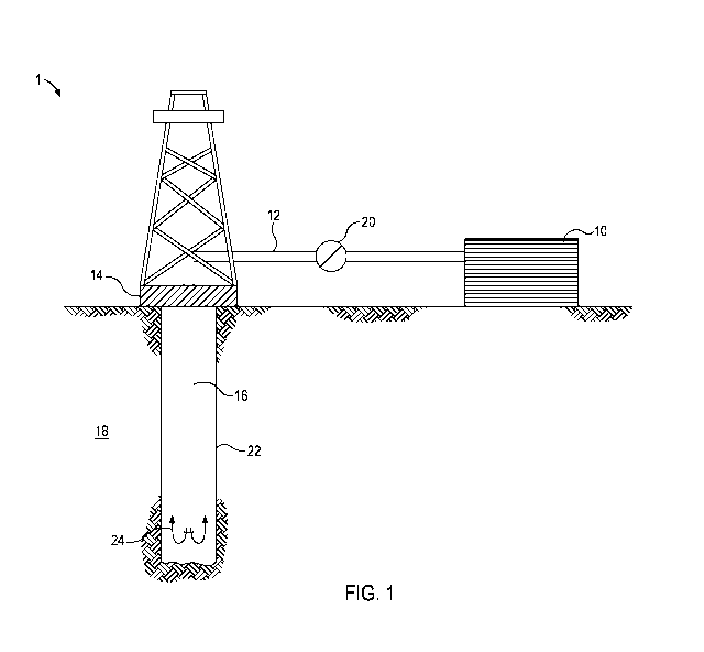
[0004] FIG. 1
depicts an embodiment of a system configured for
delivering a wellbore fluid to a downhole location according to at least some
embodiments described herein.
DETAILED DESCRIPTION
[0005] The
embodiments described herein relate to wellbore additives.
More specifically, the embodiments described herein relate to liquid additives
converted to solid additives, specifically, as liquid-infiltrated porous
silica (LIPS),
and the use of LIPS in flowable bulk solid wellbore additives.
[0006]
As used herein, the term "flowable bulk solid" refers to powders,
particulates, or mixtures thereof that have less than a 450 angle of repose
according to ASTM D6393-14, Section 1.3.1: Measurement of Carr Angle of
Repose). A flowable bulk solid may consist of a single component (e.g., the
la
CA 2974252 2018-10-15
CA 02974252 2017-07-18
WO 2016/140656 PCT/US2015/018586
LIPS described herein) or multiple components (e.g., the LIPS described herein
in combination with weighting agents).
[0007] As used herein, the
terms "liquid-infiltrated porous silica" and
"LIPS" refers to a porous silica particle having liquid-infiltrated into the
pores of
the particle. The LIPS described herein that are included in the flowable bulk
solids have an amount of liquid-infiltrated into the pores of the silica
particles
such that the LIPS are flowable (i.e., have less than a 45 angle of repose
according to ASTM D6393-14, Section 1.3.1: Measurement of Carr Angle of
Repose).
[0008] As described
previously, specialty storage facilities and
mixing equipment may be required at a well site to accommodate the use of
liquid wellbore additives. Without being limited by theory, it is believed
that the
porous silica of the LIPS described herein act as a carrier for the liquid-
infiltrated
therein. Once mixed with water, at least a portion of the infiltrated liquid
of the
LIPS may disperse into the water. Because the LIPS are flowable particulates,
the LIPS may advantageously be stored, conveyed, and mixed at the well site
(or at another site like a mixing facility) as other solid flowable additives
like
cement particles and weighting agents. This may beneficially reduce or
eliminate
the facilities, equipment, and associated costs with liquid wellbore
additives.
[0009] In some instances, the
liquids in the LIPS described herein
may be chosen to be suitable for use in removing films or coatings adsorbed on
surfaces. Many wellbore operations, such as drilling, fracturing, and remedial
operations, are conducted using oleaginous fluid systems, such as oil-based
drilling fluids, hydrocarbon-based fracturing fluid, and resin-based fluids.
When
such fluids are used downhole, the oil, hydrocarbon, and resins buildup on the
surface of the wellbore and equipment downhole like tubulars. When the
oleaginous fluid is displaced by a water-based fluid like a cement slurry or a
spacer fluid, a film or coating of the oleaginous fluid remains on the
surfaces.
This film hinders interaction between the surface and the components of the
water-based fluid. For example, a set cement produced from the cement slurry
does not adhere well, if at all, to the surface when the oleaginous film is
present.
This allows for other fluids to infiltrate the space between the set cement
and
the surface of the wellbore or the tubulars disposed therein, which may allow
for
fluids to migrate along the wellbore and hinder zonal isolation.
2
CA 02974252 2017-07-18
WO 2016/140656 PCT/US2015/018586
[0010] Liquid surfactants,
aqueous-miscible liquids (e.g., solvents
and mutual solvents), and combinations thereof may be liquids that are useful
in
removing oleaginous films from surfaces, and therefore, useful in producing
LIPS
suitable for use as a wellbore additive. Examples of such liquids suitable may
include, but are not limited to, 3-lauroylannidopropyl betaine, alkylphenol
ethoxylates (e.g., ethoxylated nonylphenol), ethoxylated C6-C10 alcohols
(e.g.,
ethoxylated hexanol), ammonium ethoxylated alkyl C6-C10 ethers sulfate,
ethylene glycol monobutyl ether, alcohols (e.g., ethyl alcohol, propyl
alcohol,
and butyl alcohol), ketones (e.g., acetone and methyl ethyl ketone),
chlorinated
solvent (e.g., methylene chloride),
hydrochloric acid, and the like, and any
combination thereof. Some of the foregoing liquids may have a sufficiently
high
viscosity that mixtures with less viscous liquids (e.g., water, alcohols, and
combinations thereof) may provide better infiltration of the porous silica.
[0011] The amount of liquid in
the LIPS may be measured by
subtracting the dry weight (i.e., with no liquid infiltration) from the
infiltrated
weight. In some instances, the amount of liquid in the LIPS may be about 1% to
about 50% by weight of the porous silica (i.e., the dry weight of the porous
silica), including subsets therebetween (e.g., about 1% to about 5%, about 1%
to about 10%, about 1% to about 25%, about 10% to about 50%, or about 25%
to about 50%.
[0012] The porous silica of
the LIPS described herein may, in some
instances, have a particle size characterized by d50 between about 0.01
microns
and about 200 microns, including subsets thereof (e.g., about 0.01 microns to
about 0.1 microns, about 0.01 microns to about 0.5 microns, about 0.01 microns
to about 1 microns, about 1 microns to about 50 microns, about 50 microns to
about 150 microns, about 100 microns to about 200 microns, about 100 microns
to about 150 microns, or about 150 microns to about 200 microns). As used
herein, the term "d50" refers to the diameter at which 50% of the particles by
weight are smaller. For example, a d50 of 120 microns means 50% of the
particles by weight are smaller than 120 microns. Particle size can be
determined by laser diffraction using ISO 13320:2009.
[0013] In some embodiments,
the surface area of the porous silica
of the LIPS described herein may, in some instances, be about 150 m2/g to
about 1000 m2/g, including subsets thereof (e.g., about 150 m2/g to about 250
m2/g, about 150 m2/g to about 500 m2/g, about 250 m2/g to about 1000 m2/g,
3
CA 02974252 2017-07-18
WO 2016/140656 PCT/US2015/018586
about 500 m2/g to about 1000 m2/g, or about 750 m2/g to about 1000 m2/g,).
Surface area can be determined by gas adsorption as described in ISO
9277:2010.
[0014] Infiltrating the porous
silica with a liquid may involve,
instilling (portion-wise or continuously) the liquid into a container of
porous silica
particle. Generally, the porous silica may be mixed, stirred, flowed, or the
like
during instillation of the liquid so that the liquid infiltrates the porous
silica more
evenly and does not build up or cause clumping, which result in LIPS with a
higher angle of repose and, potentially, nonflowable. In some instances, more
than one liquid may be used, separately or as a mixture, to infiltrate the
porous
silica.
[0015] The LIPS described
herein may be included in a flowable bulk
solid in an amount of about 1% to about 1000/0 by weight of the flowable bulk
solid. Other components in a flowable bulk solid that is suitable for use as a
wellbore additive may include, but are not limited to, weighting agents,
cement
particles, set retarders, set accelerators, fluid loss control agents,
surfactants,
polymers, and the like.
[0016] Because the specific
gravity of the porous silica of the LIPS is
greater than water, in some instances, a flowable bulk solid wellbore additive
may include less weighting agent. When included in the flowable bulk solid
wellbore additive or the wellbore fluid, the weight ratio of LIPS to weighting
agent may be about 0.1:99.9 to about 99.9:0.1, including any subset
therebetween (e.g., about 1:99 to about 99:1, about 1:99 to about 10:90, about
1:99 to about 25:75, about 1:99 to about 50:50, about 25:75 to about 75:25,
about 50:50 to about 99:1, about 75:25 to about 99:1, or about 90:10 to about
99:1).
[0017] When included in the
flowable bulk solid wellbore additive or
the wellbore fluid, the weight ratio of LIPS to cement particles may be about
0.1:100 to about 70:100, including any subset therebetween (e.g., about
0.1:100 to about 50:100, about 0.1:100 to about 25:100, about 0.1:100 to
about 10:100, or about 0.1:100 to about 1:100).
[0018] When included in the
flowable bulk solid wellbore additive or
the wellbore fluid, the set retarders and the set accelerators may each
independently be present at a weight ratio to LIPS (i.e., set retarder to LIPS
or
set accelerator to LIPS) of about 1:700 to about 100:700, including any subset
4
CA 02974252 2017-07-18
WO 2016/140656 PCT/US2015/018586
therebetween (e.g., about 1:700 to about 50:700, about 1:700 to about 10:700,
about 10:700 to about 100:700, or about 50:700 to about 100:700,).
[0019] When included in the
flowable bulk solid wellbore additive or
the wellbore fluid, the polymers and the fluid loss control agents may each
independently be present at a weight ratio to LIPS of about 1:700 to about
250:700, including any subset therebetween (e.g., about 1:700 to about
100:700, about 1:700 to about 50:700, about 1:700 to about 10:700, about
10:700 to about 250:700, about 50:700 to about 250:700, or about 100:700 to
about 250:700).
[0020] Flowable bulk solid
wellbore additives may be designed for
use in producing various water-based wellbore fluids (e.g., spacer fluids and
cement slurries). As discussed previously, the LIPS described herein may be
added as an individual component to the water or as a part of a mixture of
components to the water.
[0021] The LIPS described
herein may be present in the wellbore
fluid in an amount of about an amount of about 0.1% to about 80% by weight of
the wellbore fluid, including any subset therebetween (e.g., about 0.1% to
about
10%, about 0.1 /0 to about 25%, 1% to about 25%, about 10% to about 50%,
about 25% to about 50%, about 25% to about 80%, or about 50% to about
80%).
[0022] By way of nonlinniting
example, a spacer fluid may comprise
water, LIPS, and weighting agent and optionally further comprise polymers,
fluid
loss control agents, or a combination thereof. The concentration of LIPS and
weighting agent may be sufficient to provide for a spacer fluid with a density
of
about 9 pounds per gallon (lb/gal) (1.1 g/mL) to about 22 lb/gal (2.6 g/mL).
For
example, a spacer fluid may include water at about 29% to about 60% by
weight of the spacer fluid, LIPS at about 0.10/0 to about 70% by weight of the
spacer fluid, and weighting agent at about 0.1% to about 70% by weight of the
spacer fluid.
[0023] In some instances, the
polymers (e.g., as a viscosifier) may
be included in the spacer fluid at about 0.1% to about 20% by weight of the
spacer fluid. In some instances, the fluid loss control agents may be included
in
the spacer fluid at about 0.1% to about 20% by weight of the spacer fluid.
Combinations of the foregoing may be used.
5
CA 02974252 2017-07-18
WO 2016/140656 PCT/US2015/018586
[0024] A flowable bulk solid
wellbore additive may include one or
more of the non-liquid components in the spacer fluid. For example, the
flowable
bulk solid wellbore additive may include LIPS and weighting agents in an
appropriate ratio to provide for the desired concentrations in the spacer
fluid.
Then, if desired, fluid loss control agents, polymers, or both may be added
separately to the water or included in the flowable bulk solid wellbore
additive.
In another example, the flowable bulk solid wellbore additive may consist of
the
LIPS and the other components may be added to the water separately.
[0025] By way of another
nonlinniting example, a cement slurry may
comprise water, LIPS, weighting agent, and cement particles and optionally
further comprise set retarders, set accelerators, fluid loss control agents,
polymers, or a combination thereof. For example, a cement slurry may include
water at about 25% to about 150% by weight of the cement particles (bwoc),
LIPS at about 1% to about 70% bwoc, and weighting agents at about 10/0 to
about 70% bwoc. Further, the cement slurry may further include at least one
of:
set retarders at about 0.1% to about 100/0 bwoc, set accelerators at about
0.1%
to about 10 /0 bwoc, fluid loss control agents at about 0.1% to about 10%
bwoc,
polymers (e.g., as a viscosifier) at about 0.01% to about 25% bwoc.
[0026] Similar to spacer
fluids, a flowable bulk solid wellbore
additive may include one or more of the non-liquid components in the cement
slurry. For example, the flowable bulk solid wellbore additive may include the
cement particles, the LIPS, and the weighting agents. In another example, the
flowable bulk solid wellbore additive may include the LIPS and the weighting
agent. Then, this flowable bulk solid wellbore additive and cement particles
may
be added separately to water. One skilled in the art will recognize the
plurality of
combinations of the foregoing components of the cement slurry that can be used
to design a flowable bulk solid wellbore additive.
[0027] The LIPS and wellbore
fluids may be implemented in
cementing operations and corresponding wellbore systems.
[0028] By way of nonlinniting
example, an oleaginous drilling fluid
may be displaced by a spacer fluid followed by a cement slurry, where the
spacer fluid, the cement slurry, or both are produced using LIPS.
[0029] In another nonlimiting
example, an oleaginous drilling fluid
may be displaced by a cement slurry produced with the LIPS described herein.
6
CA 02974252 2017-07-18
WO 2016/140656 PCT/US2015/018586
[0030] In both of the
foregoing examples, the liquid in the LIPS may
be dispersed in the water of the corresponding fluid and at least partially
remove
an oleaginous film on the wellbore, the tubulars disposed therein, or both.
After
allowing the cement slurry to set, the set cement may more effectively bond to
the tubulars, the wellbore, or both because at least some of the oleaginous
film
had been removed from the surfaces thereof.
[0031] In various embodiments,
systems configured for preparing,
transporting, and delivering the wellbore fluids (e.g., spacer fluids and
cement
slurries) produced with the flowable bulk solid wellbore additives that
include
LIPS described herein to a downhole location are described. In various
embodiments, the systems can comprise a pump fluidly coupled to a tubular
(e.g., a casing, drill pipe, production tubing, coiled tubing, etc.) extending
into a
wellbore penetrating a subterranean formation, the tubular may be configured
to
circulate or otherwise convey a wellbore fluid produced with the flowable bulk
solid wellbore additives that include LIPS described herein. The pump may be,
for example, a high pressure pump or a low pressure pump, which may depend
on, inter alia, the viscosity and density of the wellbore fluid, the type of
the
cementing operation, and the like.
[0032] In some embodiments,
the systems described herein may
further comprise a mixing tank arranged upstream of the pump and in which the
wellbore fluid is formulated (e.g., where water may be mixed with the flowable
bulk solid wellbore additives that include LIPS described herein and any other
components of the wellbore fluid). In various embodiments, the pump (e.g., a
low pressure pump, a high pressure pump, or a combination thereof) may
convey the wellbore fluid from the mixing tank or other source of the wellbore
fluid to the tubular. In other embodiments, however, the wellbore fluid can be
formulated offsite and transported to a worksite, in which case the wellbore
fluid
may be introduced to the tubular via the pump directly from a transport
vehicle
or a shipping container (e.g., a truck, a railcar, a barge, or the like) or
from a
transport pipeline. In yet other embodiments, the wellbore fluid may be
formulated on the fly at the well site where components of the wellbore fluid
(e.g., the flowable bulk solid wellbore additives that include the LIPS
described
herein and any other components of the wellbore fluid) are pumped (e.g., via
pneumatic feeding) from a transport (e.g., a vehicle or pipeline) and mixed
during introduction into the tubular. In any case, the wellbore fluid may be
7
CA 02974252 2017-07-18
WO 2016/140656 PCT/US2015/018586
drawn into the pump, elevated to an appropriate pressure, and then introduced
into the tubular for delivery downhole.
[0033] FIG. 1 shows an
illustrative schematic of a system that can
deliver wellbore fluids described herein to a downhole location, according to
one
or more embodiments. It should be noted that while FIG. 1 generally depicts a
land-based system, it is to be recognized that like systems may be operated in
subsea locations as well. As depicted in FIG. 1, system 1 may include mixing
tank 10, in which a wellbore fluid may be formulated. Again,
in some
embodiments, the mixing tank 10 may represent or otherwise be replaced with a
transport vehicle or shipping container configured to deliver or otherwise
convey
the wellbore fluid to the well site. The wellbore fluid may be conveyed via
line
12 to wellhead 14, where the wellbore fluid enters tubular 16 (e.g., a casing,
drill pipe, production tubing, coiled tubing, etc.), tubular 16 extending from
wellhead 14 into wellbore 22 penetrating subterranean formation 18. Upon
being ejected from tubular 16, the wellbore fluid may subsequently return up
the
wellbore in the annulus between the tubular 16 and the wellbore 22 as
indicated
by flow lines 24. In other embodiments, the wellbore fluid may be reverse
pumped down through the annulus and up tubular 16 back to the surface,
without departing from the scope of the disclosure. Pump 20 may be configured
to raise the pressure of the wellbore fluid to a desired degree before its
introduction into tubular 16 (or annulus). It is to be recognized that system
1 is
merely exemplary in nature and various additional components may be present
that have not necessarily been depicted in FIGURE 1 in the interest of
clarity.
Non-limiting additional components that may be present include, but are not
limited to, supply hoppers, valves, condensors, adapters, joints, gauges,
sensors, compressors, pressure controllers, pressure sensors, flow rate
controllers, flow rate sensors, temperature sensors, and the like.
[0034] One skilled in the art,
with the benefit of this disclosure,
should recognize the changes to the system described in FIG. 1 to provide for
other cementing operations (e.g., squeeze operations, reverse cementing (where
the cement is introduced into an annulus between a tubular and the wellbore
and returns to the wellhead through the tubular), and the like).
[0035] It is also to be
recognized that the disclosed wellbore fluids
and components thereof may also directly or indirectly affect the various
downhole equipment and tools that may come into contact with the treatment
8
CA 02974252 2017-07-18
WO 2016/140656 PCT/US2015/018586
fluids during operation. Such equipment and tools may include, but are not
limited to, wellbore casing, wellbore liner, completion string, insert
strings, drill
string, coiled tubing, slickline, wireline, drill pipe, drill collars, mud
motors,
downhole motors and/or pumps, surface-mounted motors and/or pumps,
centralizers, turbolizers, scratchers, floats (e.g., shoes, collars, valves,
etc.),
wellbore projectiles (e.g., wipers, plugs, darts, balls, etc.), logging tools
and
related telemetry equipment, actuators (e.g., electromechanical devices,
hydronnechanical devices, etc.), sliding sleeves, production sleeves, plugs,
screens, filters, flow control devices (e.g., inflow control devices,
autonomous
inflow control devices, outflow control devices, etc.), couplings (e.g.,
electro-
hydraulic wet connect, dry connect, inductive coupler, etc.), control lines
(e.g.,
electrical, fiber optic, hydraulic, etc.), surveillance lines, drill bits and
reamers,
sensors or distributed sensors, downhole heat exchangers, valves and
corresponding actuation devices, tool seals, packers, cement plugs, bridge
plugs,
and other wellbore isolation devices, or components, and the like. Any of
these
components may be included in the systems generally described above and
depicted in FIG. 1.
[0036] Embodiments disclosed herein include:
Embodiment A: a method that includes adding a flowable bulk solid
into an aqueous fluid to produce a wellbore fluid, wherein the flowable bulk
solid
comprises a liquid-infiltrated porous silica, wherein the liquid comprises a
liquid
surfactant, an aqueous miscible fluid, or both; and introducing the wellbore
fluid
into a wellbore penetrating a subterranean formation;
Embodiment B: a composition that includes a flowable bulk solid
that includes a liquid-infiltrated porous silica, wherein the liquid comprises
a
liquid surfactant, an aqueous miscible fluid, or both; and
Embodiment C: a system that includes a tubular extending into a
wellbore penetrating a subterranean formation (e.g., extending from a
wellhead)
where an annulus is defined between the tubular and the wellbore; and a pump
fluidly coupled to the tubular, wherein the tubular, the annulus, or both
contain
a wellbore fluid produce by mixing water with a flowable bulk solid that
includes
a liquid-infiltrated porous silica, wherein the liquid comprises an aqueous
miscible fluid, a liquid surfactant, or both.
[0037] Each of embodiments A,
B, and C may have one or more of
the following additional elements in any combination: Element 1: wherein the
9
CA 02974252 2017-07-18
WO 2016/140656
PCT/US2015/018586
liquid-infiltrated porous silica is present in the flowable bulk solid at
about 0.1%
to about 100% by weight of the flowable bulk solid; Element 2: wherein the
wellbore fluid, the flowable bulk solid, or the composition further comprises
a
weighting agent that is different than the liquid-infiltrated porous silica;
Element
3: Element 2 and wherein a weight ratio of the liquid-infiltrated porous
silica to
the weighting agent is about 0.1:99.9 to about 99.9:0.1; Element 4: wherein
the
flowable bulk solid further includes a set retarder; Element 5: Element 4 and
wherein a weight ratio of the set retarder to the liquid-infiltrated porous
silica is
about 1:700 to about 100:700; Element 6: wherein the flowable bulk solid
further includes a set accelerator; Element 7: Element 6 and wherein a weight
ratio of the set accelerator to the liquid-infiltrated porous silica is about
1:700 to
about 100:700; Element 8: wherein the wellbore fluid, the flowable bulk solid,
or
the composition further comprises a fluid loss control agent that is different
than
the liquid-infiltrated porous silica; Element 9: Element 8 and wherein a
weight
ratio of the fluid loss control agent to the liquid-infiltrated porous silica
is about
1:700 to about 250:700; Element 10: wherein the wellbore fluid, the flowable
bulk solid, or the composition further comprises a polymer; Element 11:
wherein
a weight ratio of the polymer to the liquid-infiltrated porous silica is about
1:700
to about 250:700; and Element 12: wherein the wellbore fluid, the flowable
bulk
solid, or the composition further comprises cement particles.
[0038] By way
of non-limiting example, exemplary combinations
applicable to Embodiments A, B, and C include: Element 2 and optionally
Element 3 in combination with Element 4 and optionally Element 5; Element 2
and optionally Element 3 in combination with Element 6 and optionally Element
7; Element 2 and optionally Element 3 in combination with Element 8 and
optionally Element 9; Element 2 and optionally Element 3 in combination with
Element 10 and optionally Element 11; Element 4 and optionally Element 5 in
combination with Element 6 and optionally Element 7; Element 4 and optionally
Element 5 in combination with Element 8 and optionally Element 9; Element 4
and optionally Element 5 in combination with Element 10 and optionally Element
11; Element 6 and optionally Element 7 in combination with Element 8 and
optionally Element 9; Element 6 and optionally Element 7 in combination with
Element 10 and optionally Element 11; Element 8 and optionally Element 9 in
combination with Element 10 and optionally Element 11; Element 1 in
CA 02974252 2017-07-18
WO 2016/140656 PCT/US2015/018586
combination with any of the foregoing; and Element 1 in combination with one
of
Elements 2-12.
[0039] Embodiment A may have
one or more of the following
additional elements alone or in combination with one or more of Elements 1-12:
Element 13: wherein the wellbore fluid is a spacer fluid and the method
further
comprises: introducing an oleaginous drilling fluid into the wellbore;
introducing
the spacer fluid into the wellbore after the oleaginous drilling fluid; and
introducing a cement slurry into the wellbore after the spacer fluid; and
Element
14: wherein the wellbore fluid is a cement slurry and further comprises cement
particles, and wherein the method further comprises: introducing an oleaginous
drilling fluid into the wellbore; and introducing the slurry into the wellbore
after
the oleaginous drilling fluid. By way of non-limiting example, exemplary
combinations applicable to Embodiment A include: Element 13 in combination
with one or more of Elements 1-2, 8-12 including in the foregoing
combinations;
and Element 14 in combination with one or more of Elements 1-12 including in
the foregoing combinations.
[0040] Unless otherwise
indicated, all numbers expressing quantities
of ingredients, properties such as molecular weight, reaction conditions, and
so
forth used in the present specification and associated claims are to be
understood as being modified in all instances by the term "about."
Accordingly,
unless indicated to the contrary, the numerical parameters set forth in the
following specification and attached claims are approximations that may vary
depending upon the desired properties sought to be obtained by the
embodiments of the present invention. At the very least, and not as an attempt
to limit the application of the doctrine of equivalents to the scope of the
claim,
each numerical parameter should at least be construed in light of the number
of
reported significant digits and by applying ordinary rounding techniques.
[0041] One or more
illustrative embodiments incorporating the
invention embodiments disclosed herein are presented herein. Not all features
of
a physical implementation are described or shown in this application for the
sake
of clarity. It is understood that in the development of a physical embodiment
incorporating the embodiments of the present invention, numerous
implementation-specific decisions must be made to achieve the developer's
goals, such as compliance with system-related, business-related, government-
related and other constraints, which vary by implementation and from time to
11
CA 02974252 2017-07-18
WO 2016/140656 PCT/US2015/018586
time. While a developer's efforts might be time-consuming, such efforts would
be, nevertheless, a routine undertaking for those of ordinary skill in the art
and
having benefit of this disclosure.
[0042] While compositions and
methods are described herein in
terms of "comprising" various components or steps, the compositions and
methods can also "consist essentially of" or "consist of" the various
components
and steps.
[0043] To facilitate a better
understanding of the embodiments of
the present invention, the following examples of preferred or representative
embodiments are given. In no way should the following examples be read to
limit, or to define, the scope of the invention.
EXAMPLES
[0044] Example 1. Five liquids
(Table 1) were analyzed for their
efficacy on removing oleaginous films: (1) water as a control, (2) BARAKLEANO
casing cleaner (a surfactant solution, available from Halliburton Energy
Services,
Inc.) in water, (3) 8.4% solution of OPTINIATm 300 resin emulsifier (a liquid
emulsifier, available from Global Specialty Products USA, Inc.) in water, (4)
8.4% solution of 5-1718 (a mutual solvent, available from Halliburton Energy
Services, Inc.), and (5) 15% HCI in water.
[0045] A wettability meter was
calibrated to 175 Hogan units (Hn)
with a surfactant solution in water, then cleaned. Then, the wettability meter
was filled with an oleaginous fluid of WELLLOCK resin (a resin-based fluid,
available from Halliburton Energy Services, Inc.), which was subsequently
poured out leaving an oleaginous film on the surfaces of the wettability
meter.
The film weight was measured, and the wettability meter filled with one of the
liquid test samples and stirred. The Hn values were measured as a function of
time. After the Hn values reached a maximum, the % amount of resin removed
from the surfaces was calculated by weighing the remaining resin. Table 1
provides the initial Hn values (after the liquid test sample was added), the
final
Hn values, the time to reach the final Hn value, and the % film remaining.
Based
on the % film remaining, it is clear that the tested fluids 2-5 would be
suitable
for use as liquids in the LIPS described herein.
12
CA 02974252 2017-07-18
WO 2016/140656
PCT/US2015/018586
Table 1
Liquid Test Initial Hn Final Hn Time to Final % Film
Fluid Hn (sec) Remaining
1 60 160 319 48%
2 50 167.5 1060 19%
3 160 175 132 19.5%
4 90 140 390 19%
[0046] Example 2. MUSOLC) A solvent (a mutual-solvent mixture,
available from Halliburton Energy Services, Inc.) was added dropwise to
.. SIPERNATC) 22 silica (a high-surface area, porous silica, available from
Evonik
Industries) until the porous silica was loaded with 2 nnL of MUSOLC) A solvent
per gram of SIPERNATC) 22 silica. The specific gravity of the resultant LIPS
was
1.2566 g/nnL. The resultant LIPS was dry mixed with cement particles. To test
the resin cleaning ability of a cement slurry produced from the LIPS/cement
particle blend, the LIPS/cement particle slurry was added to the wettability
apparatus to designate the 175 Hn setpoint. Then, the slurry was removed and
the wettability apparatus cleaned. 150 nnL of WELLLOCKC) resin at about 80 F
was then placed in the wettability apparatus. While mixing at a constant RPM
in
the wettability meter and maintaining about 80 F, the slurry was added to the
WELLLOCKC) resin in 5 vol0/0 increments. The Hn were measured after each
addition (Table 2). The mixture reached 175 Hn at about a 50:50 mixture of the
WELLLOCKC) resin:slurry, which indicates that wettability was achieved. This
demonstrates that about 5% MUSOLC) A solvent bwoc is enough to achieve
wettability (i.e., remove the WELLLOCKC) resin from the surfaces), thereby
.. demonstrating the efficacy of the LIPS described herein.
13
Table 2
WELLLOCK Slurry (vol%) Hn
Resin (vol%)
75 25 0
70 30 0
65 35 0
60 40 0
55 45 150
50 50 175
45 55 175
40 60 185
35 65 190
30 70 190
[0047]
Therefore, the present invention is well adapted to attain the
ends and advantages mentioned as well as those that are inherent therein. The
particular embodiments disclosed above are illustrative only, as the present
invention may be modified and practiced in different manners apparent to those
skilled in the art having the benefit of the teachings herein. Furthermore, no
limitations are intended to the details of construction or design herein
shown, other
than as described herein below. It is
therefore evident that the particular
illustrative embodiments disclosed above may be altered, combined, or modified
and all such variations are considered within the scope of the present
invention.
The invention illustratively disclosed herein suitably may be practiced in the
absence of any element that is not specifically disclosed herein and/or any
optional
element disclosed herein. While compositions and methods are described in
terms
of "comprising," "containing," or "including" various components or steps, the
compositions and methods can also "consist essentially of" or "consist of" the
various components and steps. All numbers and ranges disclosed above may vary
by some amount. Whenever a numerical range with a lower limit and an upper
limit is disclosed, any number and any included range falling within the range
is
14
CA 2974252 2018-10-15
specifically disclosed. In particular, every range of values (of the form,
"from about
a to about b," or, equivalently, "from approximately a to b," or,
equivalently, "from
approximately a-b") disclosed herein is to be understood to set forth every
number
and range encompassed within the broader range of values. Also, the terms
herein
below have their plain, ordinary meaning unless otherwise explicitly and
clearly
defined by the patentee. Moreover, the indefinite articles "a" or "an," as
used
herein below, are defined herein to mean one or more than one of the element
that
it introduces.
CA 2974252 2018-10-15