Note: Descriptions are shown in the official language in which they were submitted.
CA 02974529 2017-07-20
WO 2016/118865 PCT/US2016/014525
AUTOMATED MATTRESS MANUFACTURING PROCESS AND APPARATUS
BACKGROUND
11-00011 The present disclosure generally relates to mattress manufacture, and
more
particularly, to an automated mattress manufacturing process and apparatus for
manufacturing mattresses, e.g., pocketed coil containing mattresses.
[0002] Current processes for manufacturing a mattress include numerous steps
that are
performed utilizing manual labor. Not surprisingly, the assembly process has
inherent
variability as these particular steps are operator driven and manually
performed. Moreover, the
time to perform the above described processes can be lengthy.
BRIEF SUMMARY
[0003] Disclosed herein are automated systems and processes for fabricating a
mattress.
In one embodiment, the automated system includes a plurality of stations
including an
automated coil unit assembly station comprising a coiler in operative
communication with a coil
staging apparatus to form a continuous string of pocketed coils; an automated
innercore
assembly station in operative communication with the coil staging apparatus
configured to
receive and cut the continuous string of pocketed coils to folin string
segments of the pocketed
coils, and assemble and adhesively attach rows of the string segments to
define a pocketed
spring innercore; an automated bucket assembly station in operative
communication with the
automated innercore assembly to receive the pocketed spring innercore, wherein
the automated
bucket assembly station is configured to form a foam bucket defined by a foam
base layer and
foam side rails about a perimeter thereof to form a cavity, wherein the
innercore is inserted into
the foam bucket to form an innercore unit and bucket assembly; and an
automated foam pick
layer pick and place assembly station for placing and securing one or more
foam layers onto
the innercore unit and bucket assembly; a common conveyor for serially
conveying an output
from the automated coil unit assembly station to the automated innercore
assembly station to the
automated bucket assembly station and to the automated foam pick layer pick
and place
assembly station to form the innercore and bucket assembly including one or
more foam layers
disposed thereon; and a manufacturing execution system and programmable logic
control for
planning, scheduling, and controlling the plurality of stations.
[0004] The disclosure may be understood more readily by reference to the
following
detailed description of the various features of the disclosure and the
examples included
therein.
1
CA 02974529 2017-07-20
WO 2016/118865 PCT/US2016/014525
BRIEF DESCRIPTION OF THE SEVERAL VIEWS OF THE DRAWINGS
[0005] Referring now to the figures wherein the like elements are numbered
alike:
[0006] Figure (FIG.) 1 schematically illustrates an automated mattress
assembly process
flow and cell layout;
[0007] FIG. 2 illustrates an exploded perspective view of an exemplary
assembled
innercore unit and bucket assembly including a foam topper layer disposed
thereon;
[0001] FIG. 3 is a perspective view of an automated continuous coil string
staging
apparatus;
[0002] FIG. 4 is a perspective view of the continuous coil staging apparatus
of FIG. 3;
[0003] FIG. 5 is a perspective view of the input mechanism of the continuous
coil
staging apparatus of FIG. 3;
[0004] FIG. 6 is a perspective view of the output mechanism of the continuous
coil
staging apparatus of FIG. 3;
[0005] FIG. 7 is a perspective view of a plurality of continuous coil staging
apparatuses.
[0006] FIG. 8 illustrates a perspective view of an automated innercore
assembler;
[0008] FIGS. 9-16 sequentially illustrate the innercore assembler during
manufacture of
the innercore;
[0009] FIG. 17 depicts a perspective view of an automated apparatus for
accurately
securing one or more foam topper layers onto an innercore unit and bucket
assembly in
accordance with an embodiment of the present disclosure;
[0010] FIG. 18 depicts a perspective top down view of an adhesive applicator
station
utilized in the apparatus of FIG. 17;
[0011] FIG. 19 depicts a side view of an exemplary glue bridge for the
adhesive
applicator station of FIG. 18;
[0012] FIGS. 20-21 depict partial perspective views of an innercore unit and
bucket
assembly alignment station utilized in the apparatus of FIG. 17;
[0013] FIG. 22 depicts a perspective view of a foam layer sizing and robotic
transfer
station utilized in the apparatus of FIG. 17;
[0014] FIG. 23 depicts a perspective view of an exemplary sizing table
utilized in the
foam layer sizing and robotic transfer station of FIG. 17;
2
CA 02974529 2017-07-20
WO 2016/118865 PCT/US2016/014525
[0015] FIG. 24 provides a top down view of the exemplary sizing table with
positioning of the lifting units utilized in the foam layer sizing and robotic
transfer station of
FIG. 17;
[0016] FIGS. 25-26 illustrate front and rear facing perspective views of a
gripper
assembly for use in compressing and stretching a foam layer in the foam layer
sizing and
robotic transfer station in accordance with an embodiment of the present
disclosure;
[0017] FIG. 27 illustrates a sectional view of the gripper assembly of FIGS.
25-26;
[0018] FIG. 28 provides a top down view of the lifting assembly for use in the
foam
layer sizing and robotic transfer station in accordance with an embodiment of
the present
disclosure;
[0019] FIG. 29 depicts an exemplary lifting unit for use in the lifting
assembly in
accordance with the present disclosure; and
[0020] FIG. 30 depicts the lifting assembly positioned to lift a foam layer
from the
sizing table of FIG. 18;
[0021] FIGS. 31-32 depict a perspective view and an end on view, respectively,
of a
compression station utilized in the apparatus of FIG. 17;
[0022] FIG. 33 illustrates an exemplary process flow for assembling a foam
topper
layer(s) onto an innercore unit and bucket assembly in accordance with the
present disclosure;
[0023] FIGS. 34-37 illustrate an automated foam encasement bucket assembly
apparatus.
DETAILED DESCRIPTION
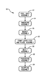
[0024] Disclosed herein are automated systems and processes for manufacturing
mattresses. As shown in FIG. 1, the automated system 10 and process for
manufacturing
mattresses generally includes multiple stations for coil unit assembly 12,
innercore unit
assembly station 14, innercore and bucket assembly 16, and foam layer pick and
placement onto
the innercore and bucket assembly 18. Each station in the automated system 10
includes a
common conveyor, e.g., a plurality of tables including motorized rollers and
coplanar transport
surfaces, in serial communication therewith to automatically transport the
mattress as it is being
manufactured. In some instances, an automated guide vehicle may be utilized to
facilitate
transfer of specific components to the different stations so as to complete
the assembly within an
individual station, thereby further automating the assembly thereof. For
example, different foam
layers, side rails, or the like, may be selected from a computer controlled
inventory and brought
to the respective system for assembly. Optionally, the automated system 10 may
further include
3
CA 02974529 2017-07-20
WO 2016/118865 PCT/US2016/014525
stations for quilt assembly 20, packaging assembly 22 and shipping assembly
24, wherein the
conveyor is in serial communication therewith to provide an automated system
and process for
fabricating a mattress from start to finish as well as packaging and readying
the mattress for over
the highway shipping. The automated system can be configured to provide the
packaged
mattress in close proximity to loading docks for convenient access to the
vehicles utilized or
shipping. A manufacturing execution system and programmable logic control for
planning,
scheduling, and controlling the plurality of stations.
[0025] The illustrated automated system 10 is configured to fabricate various
types of
mattresses. FIG. 2 depicts an exemplary exploded perspective view of
innerspring mattress
50 including an innercore unit and bucket assembly with foam topper layers.
The bucket 52
generally includes a planar base layer 54 dimensioned to approximate the
length and width
dimensions of the intended mattress. The planar base layer 54 may consist of
foam, fiber pad
or it may comprise a wooden, cardboard, or plastic structure selected to
provide support to
the various components that define the mattress, e.g., innercore unit, side,
end rails, and the
like. Depending on the innercore unit selected and its inherent stiffness,
stiffer or more
compliant base layers may be chosen. By way of example, the planar base layer
54 may be
formed of a high density polyurethane foam layer (20-170 pounds-force, also
referred to as
the indention load deflection (ILD)), or may be formed of several foam layers
(20-170
pounds-force ILD each), that alone or in combination, provide a density and
rigidity suitable
for the intended mattress manufacture. Other foams or fiber pads may be used.
Such a
choice is well within the skill of an ordinary practitioner.
[0026] An end and side rail assembly 56, which can be manufactured as a single
piece
or as multiple pieces, is affixed about the perimeter of the planar base layer
54 to define the
bucket. The end and side rail assembly 56 is typically constructed from a
dense natural
and/or synthetic foam material of the type commonly used in the bedding arts.
The foam
may be (but is not limited to) latex, polyurethane, or other foam products
commonly known
and used in the bedding and seating arts and having a suitable density. A
typical density is
about, but not limited to 1.0 to 3.0 lb/ft3 and more typically 1.5 to 1.9
lb/ft3, and a hardness of
35 to 70 ILD, and more typically 40 to 65. One example of such a foam is the
high density
polyurethane foam and is commercially available from the Foamex Corporation in
Linwood,
Ill. Alternatively, any foam having a relatively high indention load
deflection (ILD) would
be satisfactory for the manufacture of the end and side rail assembly.
Although a specific
foam composition is described, those skilled in the art will realize that foam
compositions
other than one having this specific density and ILD can be used. For example,
foams of
4
various types, densities, and ILDs may be desirable in order to provide a
range of comfort
parameters to the buyer.
[0027] The size of the end and side rail assembly 56 can vary according to the
mattress size and application, but each rail typically measures 3-10 inches
(7.5-25 cm) in
thickness. The depicted end and side rails are typically equal in width, and
their length is
chosen to correspond to the length of the size of mattress desired. For a
regular king size or
queen size mattress, the length of rails can be about 78.5 inches (200 cm),
although the length
can vary to accommodate the width of the header or footer, if the header or
footer is to extend
across the full width of the base platform 102. Similarly, the header/footer
piece typically
has a thickness of about 3-10 inches (7.7-25 cm), and the width is chosen to
correspond to the
width of the size of mattress desired. In the case of a regular king size
mattress the width
would be about 75.25 inches (191 cm), and for a queen size mattress, the width
would be
about 59.25 inches (151 cm), depending on how the foam rails are arranged to
form the
perimeter sidewall.
[0028] The end and side rail assembly 56 can be mounted or attached to base
layer 54
by conventional means, such as (but not limited to) gluing, stapling, heat
fusion or welding,
or stitching.
[0029] The bucket 52 formed of the base layer 53 and end and side rail
assembly 56
as constructed defines a well or cavity 58. The well or cavity 58 provides a
space in which
the innercore unit 60 can be inserted.
[0030] As noted above, the innercore unit 60 may be comprised of conventional
helical or semi-helical coil springs and/or foam known and used in the art
today. The coil
springs may be open or encased in a fabric material, either individually in
pockets, in groups,
or in strings joined by fabric, all of which are well-known in the bedding
art. For many
years, one foim of spring assembly construction has been known as Marshall
Construction. In
Marshall Construction, individual wire coils are each encapsulated in fabric
pockets and
attached together in strings which are arranged to limn a closely packed array
of coils in the
general size of the mattress. Examples of such construction are disclosed in
U.S. Pat. No.
685,160, U.S. Pat. No. 4,234,983, U.S. Pat. No. 4,234,984, U.S. Pat. No.
4,439,977, U.S. Pat.
No. 4,451,946, U.S. Pat. No. 4,523,344, U.S. Pat. No. 4,578,834, U.S. Pat. No.
5,016,305 and
U.S. Pat. No. 5,621,935.
[0031] Alternatively, the innercore unit 60 may be formed of foam or a
combination
of foam and coils springs. The foam, in some embodiments, can be a monolithic
block of a
Date Recue/Date Received 2022-06-17
CA 02974529 2017-07-20
WO 2016/118865 PCT/US2016/014525
single type of resilient foam selected from foams having a range of densities
(themselves
well-known in the art) or multiple foam layers for supporting one or more
occupants during
sleep. In one embodiment, foam within the innercore unit is made of any
industry-standard
natural and/or synthetic foams, such as (but not limited to) latex,
polyurethane, or other foam
products commonly known and used in the bedding and seating arts having a
density of 1.5 to
1.9 lb/ft3 and 20 to 35 pounds-force ILD. Although a specific foam composition
is
described, those skilled in the art will realize that foam compositions other
than one having
this specific density and ILD can be used. For example, foams of various
types, densities,
and ILDs may be desirable in order to provide a range of comfort parameters to
the buyer.
[0032] In an alternative embodiment, the foam innercore unit may comprise one
or
more horizontal layers of multiple types of foams arranged in a sandwich
arrangement. This
sandwich of different foams, laminated together, may be substituted for a
homogeneous foam
block of a single density and/or ILD.
[0033] In a further embodiment, the foam core may comprise one or more
vertical
regions of different foam compositions (including vertical regions having
multiple horizontal
layers), where the different foams are arranged to provide different amounts
of support (also
referred to as "firmness" in the art) in different regions of the sleeping
surface.
[0034] Accordingly, the present disclosure is not limited to any particular
type of
foam density or ILD or even to a homogenous density/ILD throughout the foam
core.
[0035] Still further, the innercore unit 60 may comprise one or more air
bladders by
themselves or in combination with coil springs, foam, or combinations thereof.
[0036] The innercore unit and bucket assembly are then overlayed with one or
more
foam topper layers 62 on the top surfaces, and the whole assembly is encased
within a
ticking, often quilted, that is sewn closed around its periphery to a border
or boxing. After
assembly, the mattress can be covered by any other decorative covering or
pillow-top. In the
present disclosure, the apparatus and process are directed to precision
placement and
securement of the one or more foam top layers 62 to the top surface of the
innercore unit and
bucket assembly.
[0037] The resulting mattresses produced by the present automated system and
process are not intended to be limited and may be of any type, dimension,
and/or shape. For
example, the mattress may be a foam mattress, a coiled mattress, a foam and
coil mattress, an
air mattress, combinations thereof, or the like. Typically, the mattress is
square or
rectangular-shaped and has a thickness ranging from about 4 inches to about 20
inches. The
length and width can vary depending on the intended application and typically
has a width of
6
about 2 feet to about 7 feet and a length of about 4 feet to about 10 feet,
although custom
sizes may require smaller or larger dimensions. For convenience, in the
present disclosure
reference will generally be made to fabrication of a mattress including an
innercore formed of
pocketed coil springs encased in foam and encapsulated in a quilt fabric
layer.
[0038] As noted above, the automated system 10 first includes coil unit
assembly 12,
which is used to form strings of pocketed coils from a wire spool. The coil
unit assembly
station 12 generally includes a coiler (not shown) and a coil unit staging
apparatus. The
coiler can be used to form a continuous string of pocketed coil strings. The
particular coiler,
which are generally well known in the art, is not intended to be limited and
may be single
head, dual head or the like and. Exemplary coiling apparatuses, i.e., coilers,
are shown
without limitation, in U.S. Pat. Nos. 4,565,046; 4,439,977; 1,733,660; and
5,613,287.
[0039] FIGS. 3-6 depict a coil string staging apparatus 100 suitable for use
in the
present disclosure, which can be utilized to provide a buffer of continuous
coil string such
that manufacturing down-time is reduced. Specifically, the coil string staging
apparatus 100
can be disposed between a coiler and an innercore assembly station such that
the coil string
staging apparatus receives a continuous coil string that is produced by the
coiler prior to the
continuous coil string being sent to the innercore assembly station, also
referred to herein as
the assembler. In such aspects, the continuous coil string staging apparatus
can have a buffer
capacity of a portion of the continuous coil string such that there is always
continuous coil
string available to the assembler.
[0040] The term "continuous coil string" as used herein means that a string of
coils is
substantially unbroken and is substantially longer in length than a segment
utilized for an
innercore. That is, the coil string is not yet cut to a length needed for
producing an innercore
for a particular mattress assembly. Typically, a continuous coil string will
be cut to the
appropriate length at the innercore assembly station during assembly.
[0041] As shown, the coil string staging apparatus 100 can include an input
102 from
the coiler, a staging buffer 104, and an output 106 to the assembler. The
input 102 is
configured to receive a continuous coil string 108 from the coiler as it is
being produced. As
shown, in some aspects the staging buffer 104 can store at least a portion of
the continuous
coil string 108. Still further, the output can be configured to output¨or
discharge¨the
portion of the continuous coil string 108 that is stored in the staging buffer
104.
[0042] FIGS. 3-5 illustrate, among other things, an example of an input 102
for use
with the coil staging apparatus 100. As shown, for example, the input 102 can
include a
7
Date Recue/Date Received 2022-06-17
CA 02974529 2017-07-20
WO 2016/118865 PCT/US2016/014525
receiving mouth 110 that is configured to receive the coil string 108.
Specifically, the mouth
110 can be appropriately dimensioned to allow the string of pocketed coils 108
to pass
therethrough unabated. The input 102 can also include a conveyor 112 or
conveyor system
that is configured to move the string 108 through the input 102. In some
aspects, the
conveyor 112 includes a motor 114 that is configured to drive the conveyor 112
and thus
actively move the coil string 108 through the input. The conveyor 112 can be
any conveyor
or conveyor system that is capable of moving the string 108 into the staging
buffer 104. For
example, the conveyor 112 can be any of a wheel, star wheel, belt conveyor, or
roller
conveyer. In some aspects, the input 102 can be disposed above the staging
buffer 104 such
that as the string 108 is moved through the input 102 it falls into the
staging buffer 104.
Additionally and without limitation, the input 102 can be directly coupled to
a support on or
adjacent to an end of the staging buffer 104. As shown in FIGS. 3-5, the input
102 can also
include a guide 116 configured to guide the coil string 108 from the coiler to
the conveyor
112 and through the input 102.
[0043] A staging buffer 104 for use in the coil string staging apparatus is
also
illustrated in FIGS. 3-6. In some aspects, the staging buffer 104 is
configured to store a
buffer of a continuous coil string. As such, the staging buffer 104 can be of
any shape that is
suitable for storing coil strings such as portions of the continuous coil
string 108. For
example and without limitation, the staging buffer 104 as shown in FIGS. 3-5,
can be
generally rectangular in shape. In other aspects, the staging buffer can be
square, triangular,
round, cylindrical, octagonal, or any other shape.
[0044] As shown more clearly in FIG. 4, the staging buffer 104 can have a
proximal
input end 118, a distal output end 120, a first side wall 122, a second side
wall 124, and a
floor 126 disposed therebetween. The proximal distal end 118 can be configured
to support
an input 102¨either by having the input 102 disposed an adjacent distance from
the proximal
end as shown, or by having the input 102 disposed directly over the end 118
(not shown).
The distal output end 120 can be configured to support an output 106 either by
having the
output 106 disposed an adjacent distance from the distal end 120, or by having
the output 106
disposed directly over the end 120 as shown in FIG. 4. First and second side
walls 122, 124
can span between the proximal end 118 and the distal end 120. The floor 126
also spans
between the proximal and distal ends 118, 120, as well as the first and second
side walls 122,
124. Optionally, in some aspects, the staging buffer 104 can include casters
128 such that the
staging buffer can be easily maneuvered.
8
CA 02974529 2017-07-20
WO 2016/118865 PCT/US2016/014525
[0045] In some aspects, the staging buffer 104 can be at least partially
transparent
such that any coil string stored within the staging buffer is visible through
at least a portion of
the staging buffer. For example, the first side wall 122, the second side wall
124, the
proximal end 118, and/or the distal end 120 can be formed of transparent
material such as
glass, plastics, polymethyl methacrylate (PlexiglassTm), perforated plastic or
metal sheeting,
plastic or wire meshes, hardware cloths, or any other material that allows the
coils to be seen
when stored in the staging buffer. In some aspects, only a portion of the
staging buffer can be
transparent as described. For example, the first side wall 122 can optionally
include a
window (not shown) formed of transparent material.
[0046] As shown in FIGS. 3-6, the staging buffer 104 can be dimensioned and
configured to store any length of coil string. For example, the staging buffer
can have a
width (such as is defined by a width of the floor 126) that is greater than a
width of the
continuous coil string. That is, the distance between the first side wall 122
and second side
wall 124 is greater than the width of the coil string. The width can be
sufficient to store only
a single coil string, or optionally, multiple rows of coil string. In some
aspects, the staging
buffer 104 can be configured to store any buffer amount of coil string that is
desired. For
example, the staging buffer 104 can be configured to store at least enough
continuous coil
string 108 to form one entire mattress assembly. Alternatively, the staging
buffer 104 can be
configured to store less than one mattress assembly worth of coil string, such
as half of a
mattress assembly, one row of a plurality of rows that foul) a mattress
assembly, or any other
amount sufficient to maintain mattress assembly production goals. For example
and without
limitation, if a mattress assembly requires ten (10) rows of coil strings that
are each ten (10)
feet in length, then the length of continuous coil string required to produce
one mattress
assembly is about one hundred (100) feet. Thus, in that example, the staging
buffer 104 can
be configured to store at least about one hundred (100) feet of continuous
coil string 108.
Additionally, the staging buffer, in some aspects, can be dimensioned such
that the coil
string, when input into the staging buffer, remains untangled and neatly
stacked such that the
continuous coil string can easily pay out (i.e., discharge) from the staging
buffer.
[0047] FIG. 6 illustrates an example of an output 106 coupled to a distal end
of a
staging buffer 104. As shown, the output 106 is configured to receive the
continuous coil
string 108 from the staging buffer 104. The output 106 can be appropriately
dimensioned to
allow the string 108 to pass therethrough. The output 106 can be configured to
either actively
output or passively output the continuous coil string. "Actively output" as
used herein means
that the output conveyor is driven such that the output conveyor directly
pulls the coil string
9
CA 02974529 2017-07-20
WO 2016/118865
PCT/US2016/014525
from the staging apparatus. For example, actively outputting a coil string can
include using
an output conveyor that is driven by a motor such that the coil string is
pulled from the
buffer. "Passively output" as used herein means that the output conveyor is
not driven such
that the output conveyor guides the coil string from the staging apparatus
when the string is
pulled out of the staging apparatus by a downstream process, such as the
assembler.
[0048] For example, the output 106 can include a conveyor 130 or conveyor
system
that is configured to move the string 108 through the output 106. In some
aspects, the
conveyor includes a motor 132 that is configured to drive the conveyor 130 and
thus actively
move the coil string 108 through the output. The conveyor 130 can be any
conveyor or
conveyor system that is capable of moving the string 108 into the staging
buffer 104. For
example, the conveyor 130 can be any of a wheel, star wheel, belt conveyor,
and/or roller
conveyer. In some aspects, the output 106 can be disposed above the staging
buffer 104.
Alternatively, the output 106 can be disposed in any location that is suitable
to actively or
passively output the coil string. Additionally, the output 106 can be directly
coupled to a
distal end of the staging buffer 104, as shown in FIG. 6. The output can also
include a guide
(not shown) configured to guide the coil string 108 downstream to the
innercore assembly
station 14.
[0049] Furthermore, in use, continuous coil string staging systems can include
a
plurality of coilers, staging apparatuses, and/or innercore assemblers. In
some aspects, the
system can have one staging apparatus for every one coiler. For example, as
shown in FIG.
7, three staging apparatuses 150A, 150B, and 150C can be used to feed a single
innercore
assembly station. As such, coil string staging systems can include at least
one coiler, at least
one staging apparatus, and/or at least one assembler.
[0050] In some aspects, including but not limited to those having more than
one
coiler, staging apparatus, or assembler, each portion of the system can be
selectively and/or
independently controlled such that desired outputs are achieved.
[0051] The system can include a variety of sensors configured to monitor
various
system parameters, including but not limited to the rate and amount of
continuous coil string
produced by a coiler, the amount of coil string in the staging buffer, the
rate that continuous
coil string is input to the staging buffer, the rate that continuous coil
string is output from the
staging buffer, and/or the amount and rate of assembly. For example, the at
least one staging
apparatus can have an input and an output that are controlled so as to
regulate the amount of
coil string stored in the staging apparatus and to maximize the amount of
mattress assemblies
produced. For example, if the coiler stops producing coil string (such as,
when perfonning a
wire or fabric changeover), the input to the staging apparatus can be stopped
while
continuing to operate the output, thus depleting the buffer of coil strings
and maintaining
operation of the assembler throughout the coiler stoppage.
[0052] In other aspects, the multiple staging apparatuses 150A, 150B, and 150C
are
configured to receive pocketed coils from a coiler that are the same or of a
different
configuration.
[0053] As noted above, one or more of the continuous coil strings 108 from the
coil
unit assembly station 12 are fed to the innercore assembly station 14, wherein
the continuous
coil string is cut to a desired length, arranged in rows on an assembly table
and adhesively
attached to one another to form the desired innercore as will be described in
greater detail
below. The innercore assembly station 14 can be configured in a variety of
manners that are
sufficient to produce mattress assemblies. By way of example and without
limitation,
assemblers are generally described in U.S. Pat. No. 5,746,877.
[0054] An exemplary innercore assembly station, generally designated by
reference
numeral 200 suitable for use in the present disclosure, will now be described
and is generally
shown in FIG. 8. In some aspects, the innercore assembly station 200 is
configured to
receive a feedstock of the continuous coil string, e.g., 108, from the staging
apparatus 100 as
previously described using a feedstock conveyor 202 coupled to a string
segment holding and
transfer mechanism 203. The feedstock conveyor 202 may be actively powered or
passive.
A powered feedstock conveyor may include a counter, such as a star wheel, belt
drive or the
like (not shown), which functions to provide the desired length and number of
coils within a
given string segment. Multiple counters, e.g., multiple star wheels, or even
sensors can be
used to process multiple coil strings, wherein each counter conveys a selected
string segment
of coils having a predetermined length and number of spring coils to a second
conveyor 204.
The number of spring coils in a particular segment is predetermined based on a
desired width
(or height, in some embodiments) of the mattress. The coils in the different
strings of coils
received by each star wheel can have different diameters, spring constants,
and the like.
Thus, the innercore assembly station can select a particular counter such as
the star wheel or
alternate between different counters depending on the characteristics of the
strings of coils
desired for the mattress. Additionally, the multiple counters allow the
assembler 200 to
process strings of coils from multiple coilers simultaneously.
[0055] As discussed above, each counter of the actively powered conveyor 202
feeds
the continuous coil string 108 to a second conveyer 204. Once the
predetermined number of
11
Date Recue/Date Received 2022-06-17
CA 02974529 2017-07-20
WO 2016/118865 PCT/US2016/014525
coils is counted as it is being introduced into the second conveyor, the
continuous string 108
is cut to form a coil string segment 109 that is sent to a predetermined
location within the
second conveyor 204 (see FIG. 9). The second conveyor 204 can include two
parallel
rotatable belt tracks 206, 208 generally spaced apart at a fixed distance,
which is slightly less
than the height of the relaxed pocketed coils when vertically oriented, each
parallel track
gripping opposing ends of the coils in the string segment to move the
horizontally oriented
coils disposed on a surface 210 between the rotatable tracks 206, 208 to the
predetermined
location. Surface 210 can be fanned of a rotatable track as well. The
individual coils of the
string of pocket coils are compressed as they are fed into the conveyor 204.
Thus, as the cut
string segment 109 enters the second conveyor 204, the spring coils in the
string exert an
outward force against the parallel tracks holding the string in place on the
conveyor. After
the string segment is cut at a predetermined number of coils, the conveyor
further advances
the string segment through the conveyor 204 to a predetermined location based
on a desired
alignment for the string segment on the resulting mattress spring assembly.
[0056] Once the string segment is moved to the predetermined location on the
second
conveyor, the string segment holding and transfer mechanism 203 is moved to a
position
directly above the string segment 109. The string segment holding and transfer
mechanism
203 includes a vertically movable and rotatable carrier 214 including opposing
clamping
surfaces 216 extending therefrom with a void therebetween, forming a channel.
The
opposing surfaces are fixed at a predetermined distance from each other that
is less than the
relaxed height of the incoming spring coils (similar to the distance between
the opposing
tracks of the conveyor 202). The coils remain compressed when they are
inserted into the
channel and this compression is what retains the string of pocket coils inside
the channel
during movement of the carrier. A mechanism in the second conveyor then
quickly pushes
the string segment up into the channel of the holding mechanism without
letting the spring
coils relax and expand completely prior to entering the holding mechanism.
Because the
distance between the opposing surfaces of the channel in the holding mechanism
is less than
the relaxed height of the spring coils, the spring coils exert an outward
force on the opposing
fixed surfaces of the channel holding the spring coils in place.
[0057] Once the string segment 109 is placed into the channel of the string
segment
holding and transfer mechanism 203, the carrier 214 moves upward and rotates
90 to be in a
position to place the string segment to a mattress spring assembly being
formed on a table
218. That is, the string segment 109 is rotated from a horizontal orientation
to a vertical
orientation. The table 218 can include guide rails 219 to accommodate and
maintain
12
CA 02974529 2017-07-20
WO 2016/118865 PCT/US2016/014525
alignment of each additional string. The distance between the guide rails is
generally
equivalent to the desired height or width dimensions of the innercore. As the
carrier 214 is
rotating 900, a hot melt adhesive applicator 220 moves across the outer string
segment, if
present, of the innercore spring assembly being formed to apply an adhesive to
the outer
string segment. After rotating 90 , the holding mechanism then pushes the
string segment out
of the channel and against the spring assembly such that the adhesive adheres
the string
segment to the spring assembly being formed. This process is repeated until
the innercore
spring assembly having a predetermined number of string segments is formed
(the number of
string segments is based on the desired length or width of the mattress).
[0058] After each string segment is applied to the spring assembly, the
adhesive
applicator locator 220 traverses the length of the most-recently-applied
string segment of the
spring assembly being formed via a guide rail 221 and sprays an adhesive to
the outer surface
of that particular string segment. This adhesive serves to adhere the next
string segment
being applied by the holding and transfer string segment mechanism. The
adhesive
applicator comprises a plurality of spray nozzles fixed in a linear array.
Additionally, the
string segment of the mattress spring assembly being formed is held in a fixed
position while
the adhesive applicator traverses the length of the string segment. In other
words, the
adhesive is applied by moving the adhesive applicator along the outer surface
of a fixed (i.e.,
non-moving) string of coils.
[0059] FIGS. 9-16 generally depict the sequential steps for assembling the
innercore
at the innercore assembly station. In FIG. 9, the continuous coil string,
i.e., feedstock, from
the coil unit staging station is introduced to the feedstock conveyor 202 and
fed to the second
conveyor 204. The coils in the continuous coil string 108 are counted and cut
to define a
string segment 109, which travels along path 230 to a predetermined location
within the
channel defined by the rotatable tracks 206, 208 of the conveyor 204. In FIG.
10, the carrier
214 of the string segment holding and transfer mechanism 203 is lowered along
vertical
travel path 224 to with conveyor 204 and grab coil string segment 109. The
carrier including
coil string segment 109 within the channel is then raised vertically as
indicated by arrow 226
in FIG. 11. In FIG. 12, the carrier 214 is rotated counter-clock-wise as
indicated by arrow
228 to provide face and align with partially constructed innercore on table
218. In FIG. 13,
the adhesive applicator 220 traverses from left to right and back again as
indicated by arrow
230 to apply an adhesive to an exposed surface coil string already on table
218. In FIG. 14,
the carrier including the string segment 109 is moved toward table 218 as
indicated by arrow
232 so as to abut the string segment with a predefined force against the
previously assembled
13
CA 02974529 2017-07-20
WO 2016/118865 PCT/US2016/014525
string segments, thereby adhesively attaching the string segment 109. The
carrier 214 is then
retracted from the table 218 as indicated by arrow 234 and rotated clockwise
as indicated by
arrow 236 so as to return the original position as shown in FIGS. 15 and 16,
respectively.
[0060] The innercore, once assembled is then moved from table 218 to the
common
conveyor (not shown) in serial communication with the various stations, e.g.,
12, 14, 16, 18, etc.
In some instances, the conveyor defines a surface upon which the various
sequences are
performed to form the mattress or are independent from the station and used
for transport to an
upstream station such as in the case of the innercore assembly station feeding
the assembled
innercore to the foam encasement assembly station.
[0061] Referring now to FIGS. 34-37, there is depicted a bucket assembly
station
500, which generally include a foam rail conveyor 502, an alignment table 504,
and a robotic
lifting assembly 506 configured to pick and place a foam rail from the foam
rail conveyor
502 to the alignment table 504. While the innercore is being assembled, bucket
assembly can
occur simultaneously, wherein the completed innercore can later be inserted
into the
assembled bucket 50 (see FIG. 2) at the bucket assembly station 16.
[0062] As shown more clearly in FIG. 35, the foam rail conveyor 502 includes
an
infeed conveyor 510, an adhesive applicator 512, and an output conveyor 514,
wherein the
input and output conveyors 510, 512 feed a foam rail 509 through the adhesive
applicator
512, wherein a hot melt adhesive is automatically applied to selected surfaces
thereof. A
staging table 516 is proximate to the input conveyor and is configured to hold
a plurality of
foam side rails parallel to the input conveyor. The staging table 516 is
further configured to
periodically feed individual foam side rails onto the input conveyor 510. The
input and
output conveyors 510, 514 further include a railing 518 perpendicular to the
conveying
surface configured to align the railing through the feed path defined by the
conveyors. The
adhesive applicator 512 is similar to that described below albeit configured
to spray adhesive
along a length of a selected rail surface, which is then oriented using the
robotic lifting
assembly 506 to adhesively contact the foam layer when placed there on and at
least one end
so as to adhesively contact abutting side rails so as to form the bucket.
[0063] Referring back to FIG. 34, the robotic lifting assembly 506 generally
includes
a multi-axis functional robot 530, a movable arm 534, and a lifting assembly
532 attached to
an end of the arm 534. The robot itself is not intended to be limited and is
commercially
available from numerous sources. An exemplary industrial robot is commercially
available
from ABB Ltd. As shown more clearly in FIG. 39, the lifting assembly 520
generally
includes a plurality of adjustable u-shaped clamps 540 spaced apart along a
length of a carrier
14
CA 02974529 2017-07-20
WO 2016/118865 PCT/US2016/014525
542, which is rotatably coupled to the robot arm 534. At one end of the
carrier 542 is a
pivotally adjustable member 544. During assembly of the bucket, the robotic
lifting
assembly is adapted to pick up a rail and place the rail onto a foam base
layer using the u
shaped clamps. The robotic lifting assembly moves in response to command
signals to lift a
foam rail having adhesive applied to the selected perimeter surface to the
foam base layer.
Member 544 is utilized to exert pressure against abutting side rails at the
corners to insure
adhesive contact.
[0064] As shown in FIG. 37, the alignment table 504 includes member 556
pivotably
attached to one end of the table and configured to grab and move a foam layer
to a
predetermined location. The member is generally L-shaped and can be adjusted
as indicated
by arrow 558 for the particular length or width of the foam layer. The
alignment table
includes stationary alignment rails 550, 552 perpendicular to one another and
attached to the
table to define a base datum corner, wherein the foam layer is positioned
using member 556.
The member 556, which is adjustable along one portion of the L shape is also
movably
coupled to adjustable rails 554 so as to seat the foam layer against alignment
rails 550, 552.
The table can further include a plurality of perforations in fluid
communication with an air
source configured to provide positive or negative air flow to maintain the
position of the base
foam layer during attachment of the side rails to form the bucket or
facilitate removal.
[0065] Turning now to FIG. 17, there is depicted an automated foam layer pick
and
placement apparatus for precisely placing foam layers onto the innercore and
bucket assembly,
which is generally designated by reference numeral 300. The automated foam
layer pick and
placement apparatus 300 includes an adhesive applicator station 302 for
automatically
applying controlled amounts of adhesive in a desired pattern onto a top
surface of an
assembled innercore unit and bucket assembly (or in the case where one foam
layer has
already been placed and adhesively secured, onto the top surface of the foam
layer); an
alignment station 304 for automatically aligning and accurately defining a
position thereof;
automated delivery/transfer of a foam layer from an automated guide vehicle to
the sizing
table (not shown), a foam layer sizing and robotic transfer station 306 for
automatically
delivering, locating, sizing, picking, and placing one or more foam layers
onto the innercore
unit and bucket assembly; and a compression station 308 for compressing the
foam layer(s)
onto the innercore unit and bucket assembly to provide consistent adhesion of
the foam layer
to the underlying top surface of the innercore unit and bucket assembly. The
adhesive
applicator station 302, the alignment station 304, and compression station 308
include
CA 02974529 2017-07-20
WO 2016/118865 PCT/US2016/014525
conveyors that form the serially aligned conveyors between the different
stations, e.g., 12, 14,
16, and the like.
[0066] As shown, the adhesive applicator station 302, innercore unit and
bucket
assembly alignment station 304, and the compression station 308 are serially
aligned with one
another as shown, wherein each station includes a movable surface (e.g., a
conveyor rotatably
driven by a motor) to define a travel path of the innercore unit and bucket
assembly during
alignment and as the foam layer(s) is placed thereon. However, it should be
apparent that the
apparatus 300 is not intended to be limited to the particular configuration as
shown. Other
variations and configurations will be apparent to those skilled in the art in
view of this
disclosure.
[0067] The movable surfaces of the stations, 302, 304, and 306 are generally
coplanar
to each other to permit transfer into and out of the respective stations as
will be described in
greater detail below. The tables supporting the various movable surfaces may
also be
interconnected to provide greater stability or may be fixedly attached to the
ground. The
foam layer sizing and robotic transfer station 306 is adjacent to the serially
aligned adhesive
applicator station 302, innercore unit and bucket assembly alignment station
304, and the
compression station 306. In the embodiment as shown, the foam layer sizing and
robotic
transfer station 306 is immediately adjacent to the innercore unit and bucket
assembly
alignment station 304 to minimize the travel of the robot to effect placement
of the foam
layer from the sizing table onto the innercore unit and bucket assembly within
the innercore
unit and bucket assembly alignment station 306.
[0068] The apparatus and process is operably linked to a programmable logic
control
system (PLC system) or serial bus system and/or manufacturing execution
solution (MES
system) to plan and schedule the different process steps as well as minimize
and/or eliminate
manual labor, which represents a significant departure from prior art assembly
processes.
Each station is configured to communicate with the MES system, which are
commercially
available from a variety of suppliers, e.g., Preactor from Siemens AG.
Designing the
appropriate algorithms to perform the various steps to plan, schedule,
operate, and control the
system is well within the skill of those in the art. The data and inputs for
operating the
systems are generally available to an operator via a computer interactive
display. The various
actuators controlled by the system employed to automate the process are not
intended to be
limited to any particular type, e.g., pneumatic, hydraulic, electrical, and
the like. Suitable
actuators include servomotors, stepper motors, pneumatic actuators, hydraulic
actuators, and
the like.
16
CA 02974529 2017-07-20
WO 2016/118865 PCT/US2016/014525
[0069] Referring now to FIG. 18, there is shown a top down view of the
adhesive
applicator station 302, which includes a table 310 having a generally planar
support surface
312 configured to support the innercore unit and bucket assembly during the
process of
applying adhesive to the innercore unit and bucket assembly. The support
surface 312 can be
elevated relative to ground and may include a movable support surface (i.e., a
conveyor) for
transferring the innercore unit and bucket assembly into and out of the
station. The movable
support surface is not intended to be limited to any particular type and may
include a plurality
of rollers and/or a rotatable belt rotatably driven by a motor for
automatically moving the
innercore unit and the bucket assembly into and/or out of the adhesive
application station.
Adjustment to the speed of the movable support surface allows for tailored
feed rates to pair
the adhesive application with placement of the foam layer or the like, thereby
providing
reproducible adhesive volume application in a desired pattern.
[0070] As shown more clearly in FIG. 19, the adhesive applicator station 302
further
includes a bridge 304 carried by supports 316, wherein the bridge laterally
spans across the
length or width dimension of the support surface 312. Optionally, the bridge
may be
mounted directly to the underlying support surface 312. As shown, the bridge
316 generally
spans a width dimension of the support surface, which during operation extends
beyond a
width dimension of the innercore unit and bucket assembly. The bridge is
elevated relative to
the support surface and positioned proximate to the innercore unit and bucket
assembly
alignment station 304, wherein the bridge is at a height from the support
surface effective to
permit clearance of the innercore unit and bucket assembly, with or without
additional foam
layers disposed thereon. In some embodiments, the bridge may be vertically
movable, which
is desired for the glue application to achieve consistent glue spray patterns.
The bridge has
coupled thereto one or more adhesive applicators 318, which may be statically
or
dynamically mounted to the bridge. The adhesive applicators are oriented to
apply a desired
pattern of adhesive to a top surface of an underlying innercore unit and
bucket assembly (or
foam layer if one is already placed and secured thereto). In this manner,
adhesive may be
applied to the top surface as the innercore unit and bucket assembly (or foam
layer) as the
assembly is conveyed into and from the adhesive applicator station.
[0071] The adhesive applicator(s) 318 is configured to provide a controlled
amount of
adhesive in a desired pattern to the top surfaces innercore unit and bucket
assembly (or foam
layer). In some embodiments, the adhesive applicator(s) may be moveable across
the bridge
so that application of the adhesive can be optimally located for each size
and/or type of
17
CA 02974529 2017-07-20
WO 2016/118865 PCT/US2016/014525
innercore unit and bucket assembly and/or foam layer as well as providing a
desired pattern
of the adhesive.
[0072] In the foregoing embodiments, the application of the adhesive may be
intermittent or continuous. Similarly, the adhesive may be applied to the
entire top surface or
to selected portions thereof as may be desired in some applications. In one
embodiment, the
adhesive applicator includes a plurality of nozzles in fluid communication
with a source of
adhesive such as a hot melt adhesive. The adhesive applicator may be coupled
to a motion
detector system or sensor system (not shown) for actuating the nozzles as the
innercore unit
and bucket assembly is transferred into and/or out of the adhesive application
station 302.
Adhesive application can be triggered by the product presence sensors in
conjunction with
PLC logic code to ensure exact start and stop of adhesive application for the
particular
mattress size. The PLC/MES system may be programed to adjust the adhesive
application
based on the type of foam topper (density and ILD) and foam layer sequence
(e.g., third foam
layer on the inner core unit and bucket assembly which is close to the
mattress surface
assumes incremental movement and can require a different glue pattern compare
to other
stackedly arranged foam layers, e.g., additional foam layers and/or the first
foam layer
disposed on the innercore unit and bucket assembly).. In one embodiment, the
adhesive
applicator 318 is a dual pump spray system that provides a metered volume and
the nozzles
therein are configured to provide a desired pattern of an adhesive through the
use of the
programmable logic control device and/or glue spray pattern code/logic. For
example,
actuation of the adhesive applicator can be configured to occur upon detection
by the motion
detector system of the leading edge of the innercore unit and bucket assembly
traveling
underneath the adhesive applicator and discontinued upon detection of the
trailing edge of the
bucket. The automation provided by the adhesive applicator(s) provides
controlled adhesive
application and patterning, thereby allowing for significantly more consistent
and repeatable
application of the adhesive as compared to prior art processes. Moreover, by
providing a
specific pattern and volume of adhesive, significant cost savings can be
realized relative to
the prior art manual spray application of the adhesive by an operator.
[0073] The innercore unit and bucket assembly alignment station 304 shown in
FIGS.
20-30 includes a support surface 320 for supporting the innercore unit and
bucket assembly
during alignment as well as during foam layer placement. The support surface
320 may
include a movable support surface for transferring the innercore unit and
bucket assembly
into and out of the station. The movable support surface is not intended to be
limited to any
particular type and may include a plurality of rollers and/or a rotatable belt
rotatably driven
18
CA 02974529 2017-07-20
WO 2016/118865 PCT/US2016/014525
by a motor for automatically moving the innercore unit and the bucket assembly
into and/or
out of the adhesive application station.
[0074] The alignment station 304 further includes an adjustable rail assembly
322 for
aligning the innercore unit and bucket assembly to a precise reproducible
location. The rail
assembly generally includes two reference rails 324, 326 that collectively
define a base datum
corner of the innercore unit and bucket assembly when seated against these
rails. Reference
rail 324 extends along a side of the support surface 320 (i.e., the x-
direction and is generally
parallel to the travel path of the innercore unit and bucket assembly) and
reference rail 326 is
transverse to the support surface 320 and is positioned at the edge of the
support surface 320
(i.e., the y-direction and is generally perpendicular to the travel path of
the innercore and
bucket assembly). Reference rail 326 may be fixedly mounted to the side 328 of
the support
surface 320. Reference rail 326 is disposed at support surface end 330
generally
perpendicular to the travel path of the innercore unit and bucket assembly.
Both rails 324,
326 may be vertically retractable with respect to ground via an actuator
controlled by the
PLC system. During the alignment process, reference rail 326 is in the raised
position as
shown and during transfer from one station to another, the rail may be
retracted so as to
permit the innercore unit and bucket assembly to travel unimpeded along the
travel path.
[0075] The adjustable rail assembly further includes movable rails 332 and
334,
wherein the rails 324, 326, 332, and 334, collectively frame the innercore
unit and bucket
assembly during the alignment process with movable rails 332 and 334 pushing
the innercore
unit and bucket assembly against the reference rails, thereby establishing a
base datum
reference indicative of the exact position and orientation of the innercore
unit and bucket
assembly. Movable rail 332 is positioned parallel to the travel path of the
innercore unit and
bucket assembly and is configured to move in the y-direction so as to compress
against a
sidewall of the innercore unit and bucket assembly when in use and movable
rail 334 is
configured to push against a sidewall of the innercore unit and bucket
assembly in the x-
direction. Each of the rails 324, 326, 332, and 334 includes a planar surface
perpendicular to
the support surface. In this manner, during alignment the movable rails 332,
334 serve to
push the innercore unit and bucket assembly against reference rails 324, 326
such that a
corner of the innercore unit and bucket assembly is seated against reference
rails 324, 326 at
a precise, reproducible location and orientation.
[0076] Movable rail 332 is movably disposed on a support surface 336 that is
adjacent and coplanar to end 338 of the support surface 320. Support surface
336 includes
one or more track guides 340 that are generally perpendicular to the travel
path of the
19
CA 02974529 2017-07-20
WO 2016/118865 PCT/US2016/014525
innercore unit and bucket assembly. An arm 342 is attached at one end to a
back side of the
rail 332 and at the other end movably coupled to the track guide. The
particular numbers of
arms attached to the rail 332, three of which are shown, are not intended to
be limited. At
least one arm is operably linked to rail 332. Likewise, the number of track
guides is not
intended to be limited and will generally correspond to the number of arms. An
actuator
controlled by the PLC system is operably linked to the arm to selectively move
rail 332 along
the track guide 340.
[0077] Movable rail 334 is attached to a hinge 344 at one end 346 and to a
retractable
arm 348 at about the other end 350. The retractable arm 348 provides rotation
about an axis
of the hinge 344 such that when in use the rail 334 is positioned to be
parallel to a sidewall of
the innercore unit and bucket assembly and when not in use the rail is
retracted away from
the sidewall. As shown, retraction of the arm 348 in the direction shown by
arrow 352
swings the rail 334 out of the travel path of the innercore unit and bucket
assembly. The
hinge 344 (and rail 334) is movably coupled to guide rails 354 to effect
linear movement of
the rail along the travel path if the innercore unit and bucket assembly. When
the arm is
extended, travel of the rail 334 along the guide rails 354 permits the rail
334 to push against a
sidewall of the innercore unit and bucket assembly. Optionally, the movable
rail may further
include a stop (not shown) for receiving the rail when retracted. The stop may
be magnetic
and may include a recess for receiving the rail. One or more actuators, e.g.,
servomotors, two
of which are shown, are operably linked to the rail 334 to provide extension
and retraction of
rail as well as to movement of the rail along the guide rails.
[0078] Turning now to FIG. 22, there is shown the foam layer sizing and
robotic
transfer station 306, which generally includes a robotic lifting assembly 360
and a foam layer
sizing table 362. The robotic lifting assembly 360 moves in response to
command signals to
lift a nominally sized foam layer from the sizing table 362 and precisely
place the foam layer
onto the innercore unit and bucket assembly. The robotic lifting assembly 360
generally
includes a multi-axis functional robot 364 and a lifting assembly 368 attached
to an arm 370
of the multi-axis functional robot. The robot itself is not intended to be
limited and is
commercially available from numerous sources. An exemplary industrial robot
for picking
and placing the foam layer is commercially available from ABB Ltd.
[0079] As shown in FIGS. 23-24, the sizing table 362 includes a generally
planar
surface 372 for supporting the foam layer during the sizing process. The
planar surface 372
may include a plurality of perforations 374 extending through the surface. The
sizing table
362 further includes an adjustable rail assembly 376 shown more clearly in
FIG. 24 for sizing
CA 02974529 2017-07-20
WO 2016/118865 PCT/US2016/014525
the foam layer to a nominal size and providing a precise reproducible location
to the
apparatus. As used herein, the term nominal size is to be accorded its usual
and customary
meaning. In general, nominal size refers to a standardized dimension specific
to the intended
mattress dimension, e.g., twin, queen and the like. The nominally sized foam
layer will
generally be sized to match the length and width dimensions of the innercore
unit and bucket
assembly (or foam layer disposed thereon) to which the nominally sized foam
layer is to be
attached. The adjustable rail assembly 376 is configured to frame the foam
layer as shown in
FIG. 23 and automatically compress the foam layer to less than nominal size
followed by
stretching of the foam layer to the nominal size defined by the programmed
specification for
the particular foam layer, which is then lifted and subsequently placed on the
innercore unit
and bucket assembly via the robotic lifting assembly 360. As will be discussed
in greater
detail below, the adjustable rail assembly 376 provides a base datum corner
378 for the foam
layer, which is then matched with the base datum corner of the aligned
innercore unit and
bucket assembly to provide precise placement and orientation of the foam layer
onto the
innercore unit and bucket assembly.
[0080] The adjustable rail assembly 376 generally includes two reference rails
258,
260 adjustably positioned on the sizing table 362 that generally intersect at
one end at a right
angle on the table at a known location so as to collectively define the base
datum comer 378
for the foam layer when seated against these rails. Reference rail generally
380 generally
corresponds to a width dimension of the foam layer and reference rail 382
generally
corresponds to a length dimension of the foam layer.
[0081] The adjustable rail assembly further includes movable rails 384 and
386,
wherein the rails 380, 382, 384, and 386 collectively frame the foam layer
during the sizing
process with the movable rails 384 and 386 aligning the foam layer, which is
then
compressed by the rails 380, 382, 384, and 386. The rails may be of unitary
construction or
may comprise segments of equal or differing lengths, wherein each segment may
be
independently controlled by an actuator, e.g., a pneumatic actuator.
[0082] Movable rail 384 is positioned parallel to reference rail 380 and
movable rail
386 is positioned parallel to reference rail 382 so as to define the
adjustable rail assembly
376. Each of the rails 380, 382, 384, and 386 includes a planar surface
perpendicular to
surface 372. In this manner, during sizing the rails 380, 382, 384, 386 serve
to compress the
foam layer against the respective opposing rail.
[0083] The surface 372 further includes one or more track guides 390 that are
generally perpendicular to rails 380, 382, 384, and 386. The rails are
operably coupled to the
21
CA 02974529 2017-07-20
WO 2016/118865 PCT/US2016/014525
track guides 390 via an arm 392 attached at one end to a back side of the
rails and at the other
end movably coupled to the track guide. The particular numbers of arms
attached to the rails
are not intended to be limited. At least one arm is operably linked to the
rail. Likewise, the
number of track guides is not intended to be limited and will generally
correspond to the
number of arms. An actuator such as a servomotor controlled by the PLC system
is operably
linked to the arms to selectively and precisely move the rails along the
corresponding track
guide 390. Movable rails 384 and 386 include longer track guides to
accommodate different
size foam layers whereas rails 380 and 382 include shorter track guides to
provide
compression of the foam layer during the sizing process.
[0084] Each of the rails 380, 382, 384, and 386 further includes a gripper
assembly
for clamping onto the foam layer during the stretching step of the sizing
process. As noted
above, the foam layer is first compressed against the rails to less than
nominal size. During
the stretching step, the gripper assemblies disposed on the rails 380, 382,
384, 386 are
actuated to clamp downward onto the foam layer and rails 384, 386 are then
moved to a
predefined position. The movement of rails 384, 386 to the predefined position
stretches the
foam layer to its nominal size as defined by the foam layer specification. The
gripper
assemblies 394 are generally pivotably coupled to and spaced about the rails
to provide
controlled gripping of the foam at the edge and stretching.
[0085] The particular gripper assemblies 394 are not intended to be limited.
An
exemplary gripper assembly is shown in FIGS. 25-27, wherein the gripper
assembly 394
generally includes an actuator 396, e.g., a linear actuator or the like, that
is coupled at one end
to bar 398 and at the other end to a second actuator 397 disposed underneath
the table 362 via
a link 400 engaged within track guide 390. Actuation of the second actuator
397 effects
precision movement of the rail e.g., rail 380, across the surface 372 of the
sizing table 362.
The bar 398 is pivotably coupled to the rail and attached to a pivotably
movable upper plate
404. The rail further includes a lower plate 402 upon which an outer periphery
of the foam
layer is generally disposed on after the foam layer is placed on the sizing
table and
compressed. Actuation of the actuator 396 pivotably lowers the movable upper
plate 404 so
as to sandwich the outer periphery of the foam layer between the movable upper
plate 404
and the lower plate 402. Subsequent movement of the second actuator outwardly
from the
foam layer causes the rails to stretch the foam layer. Movement across the
table is carefully
controlled so that the foam layer is stretched to its nominal size.
[0086] In one embodiment, sensors may be located on the rails to assist in
aligning
the gripper assemblies to the edges of the foam layer. Servomotors may be
employed to
22
CA 02974529 2017-07-20
WO 2016/118865
PCT/US2016/014525
move the rails to the programmed position, e.g., moves the rails including the
gripper
assemblies to contact foam layer
[0087] As shown more clearly in FIG. 28, the lifting assembly 368 includes a
frame
410 with a primary beam 412 bisecting the frame 410 at about a midpoint.
Secondary beams
414 are coupled to the primary beam 412 and/or the frame 410 to define a
rectangularly
shaped portion of the lifting assembly having attached thereto statically
positioned lifting
units 416 in a spaced arrangement about the rectangularly shaped portion,
wherein the
rectangularly shaped portion overlays a major portion of an underlying foam
layer. The
lifting assembly 368 further includes support beams 418 for supporting movable
beams 422,
424, and 426 mounted thereto. Each movable beam 422, 424, and 426 includes
additional
lifting units 216 spacedly arranged on the beams. In some embodiments, the
position of the
lifting units 216 may be adjustable on the rail. The position of these movable
beams 422,
424, and 426 can be selected and optimized based on the dimensions of the foam
layer to be
lifted corresponding to the mattress size. For example, movable beam 422 can
be selectively
moved to accommodate the manufacture of mattresses having various lengths
e.g., standard,
long, extra-long, etc. whereas movable beams 424 and 426 can be selectively
moved to
accommodate the manufacture of mattresses having various widths, e.g., twin,
full, queen,
king, etc. The movable beams are generally positioned to overlay an edge of
the underlying
foam layer that is outside the area overlayed by the statically positioned
rectangular shaped
portion discussed above. The position of the movable beams can be programmed
in the PLC
system. Precise movement of the rails can be provided by precision ball
bearing slides or the
like. An attachment plate 428 is centrally located on the frame and provides
the means for
attaching the arm to the lifting assembly.
[0088] As shown more clearly in FIG. 29, each one of the lifting units 416
generally
includes a head 430 that supports two slides 432, 434, each of which is
provided with one or
more retractable angled needles 436 (shown extended from the head). The
needles on one
slide face towards the needles of the other slide, sloping one towards the
others. The needles
are at an angle relative to a foam layer of about 30 (150) to about 60 (120)
degrees in most
embodiments, although angles greater or less than this range can be used. In
one
embodiment, the needles are at an angle of 45 (135) degrees. Moreover, the
needles from the
respective slides are spaced by a gap 438 such that the needles from the
opposing slides
overlap when extended into the foam layer.
[0089] Both of the slides, and with them the needles that are fixed to them,
are
controlled and movable in opposite directions between an idle position, in
which the needles
23
on one slide are retracted and are at a distance from those on the other
slide, and an active
position, in which the needles of the two slides move forward, cross each
other and sloping
penetrate into the element to be picked up and, with the help of a flat head,
they are able to
gather it and transfer it according to requirements. An exemplary needle
gripper is
commercially available from Schmalz Inc. Exemplary needle grippers are
disclosed in U.S.
Patent No. 8,104,807.
[0090] FIG. 30 depicts the lifting assembly 368 positioned to lift an
exemplary
underlying foam layer 450 that has previously been compressed and stretched to
a nominal
size. The movable beams 422 and 424 are optimally positioned such that lift
units 416 are at
positions disposed over a peripheral edge of the foam layer as well as
spacedly and uniformly
arranged over an interior region of the foam layer so as to lift the foam
layer and maintain its
nominal size. In the embodiment shown, movable beam 426 is not needed to lift
this
particular sized foam layer and is positioned such that the lifting units
disposed thereon do not
overlay the foam layer.
[0091] During operation, the sizing table 362 (Fig 23) first receives a foam
layer, e.g.,
450 from a delivery system, e.g., manually placed by an operator or through an
automated
guide vehicle or robotic assist via grippers, or the like. The movable rail
sections on the sizing
table 362 are activated to match the size of the foam layer being sized. The
actuators, e.g.,
servomotors, are configured and programmed to move the rails until it contacts
the foam
layer. The adjustable rail assembly 376 holds the foam as it is transported to
the base corner
datum. The gripping assemblies 394 are then activated and the foam layer is
stretched to its
nominal size, which matches the length and width dimensions of the innercore
unit and
bucket assembly. The lifting assembly 368 is then robotically lowered onto the
foam layer
and the lifting units incorporating needles are activated to engage the foam
layer. The foam
layer at its nominal size is then placed onto the innercore unit and bucket
assembly using the
base corner datum as a reference point to provide precise placement of the
foam layer.
100921 Advantageously, the sizing function may incorporate variable
compression
forces, variable stretching forces, and clamping based on the foam type with
real time
adjustments to achieve the intended functional value desired. Consequently,
sizing of the
foam layer will reduce process variability by providing consistency in terms
of the size and
precise placement of the foam layer onto the previously aligned and known
position of the
innercore unit and bucket assembly.
24
Date Recue/Date Received 2022-06-17
CA 02974529 2017-07-20
WO 2016/118865 PCT/US2016/014525
[0093] As shown in FIGS. 31-32, the compression station 308 generally includes
a
support surface 460 coplanar and serially connected to the support surface of
the alignment
station 304. The support surface 460 may include a movable support surface for
transferring
the innercore unit and bucket assembly with the foam layer(s) thereon into and
out of the
station. The movable support surface is not intended to be limited to any
particular type and
may include a plurality of rollers and/or a rotatable belt rotatably driven by
a motor for
automatically moving the innercore unit and the bucket assembly into and/or
out of the
adhesive application station.
[0094] The compression station 308 further includes a vertically movable
platen 462
disposed above the support surface. The platen 462 may be driven by actuators
(not shown),
e.g., pneumatic actuators, hydraulic actuators, or the like that move the
platen vertically
upward and downward such that when the innercore unit and bucket assembly
having the
foam layers disposed therein are transferred to the compression station, the
platen is lowered
to compress the assembly. The compression of the assembly provides a
predetermined and
programmed pressure on the assembly to provide consistent and uniform downward
pressure
across the surface of uppermost foam layer, which serves to maximize contact
of the adhesive
between the various layers, thereby minimizing the amount of adhesive used
compared to the
prior art as well as providing reproducibility with regard to adhesive
strength.
[0095] The platen 462 has a substantially planar surface that contacts the
surface of
the uppermost foam layer. The platen is generally dimensioned such that the
substantially
planar surface can be configured to provide a constant pressure across the
entire surface of
whatever size foam layer the platen contacts. As such, the platen is generally
dimensioned to
be larger than the largest size mattress being assembled. The substantially
planar surface
may be formed of a single piece construction or may be formed of plates. In
some
embodiments, the individual plates may be independently actuatable so as to
exert differing
pressures as may be desired in some applications.
[0096] As noted above, the automated system 10 can be fully automated via a
programmable logic control and/or manufacturing execution solution system
(i.e., the
PLC/MES system) using a radio frequency identification tag (RFID) for
component
identification. By way of example, RFID tags may be affixed to the innercore
unit and bucket
assembly and/or foam layers and/or storage areas corresponding to the
particular component
for wireless recognition by the PLC/MES system. In this manner, orders can be
managed and
scheduled from the PLC/MES system. Still further, each of the various steps
for placing and
securing the foam layers onto the innercore unit and bucket assembly can be
fully automated
via the programmable logic control/manufacturing execution solution system,
thereby
requiring no operator interaction. Use of RFID tags for component
identification enhances
changeovers and allows for simple correction for variation between different
innercore and
bucket assembly types as well as different foam layer types.
[0097] Turning now to FIG. 33, the process 470 of operating the foam
encasement
assembly station 300 generally includes a first step 472 of delivering a foam
layer to the
robotic foam layer sizing and robotic transfer station 306. This step is
automatically
performed. For example, an operator can manually place the foam from inventory
on the
automated guide vehicle, which can be programmed to automatically locate and
transfer a
desired foam layer to the sizing and transfer station. The foam layer is then
sized in the
sizing station, which first compresses and then stretches the foam layer to a
nominal size as
shown in step 404.
[0098] Prior to or simultaneously with the location and sizing of the foam
layer, an
innercore and bucket assembly is provided to the adhesive application station
302 as shown
in step 406. In one embodiment, the innercore unit and bucket assembly can be
directly fed
from an innercore unit and bucket assembly station. An exemplary innercore
unit and bucket
assembly station is disclosed in US Patent Application No. 14/481,419
entitled: Mattress
Manufacturing Process and Apparatus to Michael DiMarco and filed on September
9, 2014.
For example, the innercore unit and bucket assembly can be transferred to the
conveyor of the
adhesive application station where a predetermined pattern and volume of
adhesive is then
applied to the top surface. The innercore unit and bucket assembly with the
applied adhesive
is then transferred to the alignment station for alignment. All four sides are
aligned as shown
in step 408, wherein the coordinates are provided to the programmable logic
control system.
[0099] The foam layer at the nominal size is then picked up from the foam
layer
sizing and robotic transfer station 306 and placed on the top surface of the
aligned inner core
unit and bucket assembly as shown in step 410. In this manner, the foam layer
is precisely
placed on the top surface of the innercore unit and bucket assembly (or
previously deposited
foam layer) and onto a controlled amount and defined pattern of adhesive. The
process is then
repeated until all foam layers for the mattress design build are placed as
provided in step 412.
[0100] Subsequent to foam placement on the innercore and bucket assembly (or
previously deposited foam layer), the assembly is transferred to the
compression station,
wherein downward pressure is applied onto the assembly to insure maximum and
consistent
adhesion of the foam layer to the innercore unit and bucket assembly. In
situations where
26
Date Recue/Date Received 2022-06-17
CA 02974529 2017-07-20
WO 2016/118865 PCT/US2016/014525
multiple foam layers are placed, the programmable logic control system may be
programmed
to provide the step of compression after each foam layer is adhesively placed,
after selected
foam layers are placed, or after all of the layers are placed. The system
provides latitude as to
when this may occur.
[0101] Referring back to Figure 1, an exemplary process 10 flow for the
automated
manufacturing of a mattress in accordance with an embodiment is shown. hi
exemplary
embodiments, the automated manufacturing process 10 includes, but is not
limited to, coil unit
assembly 12, innercore assembly 14, bucket assembly 16, foam encasement
assembly 18, quilt
assembly 20, packaging assembly 22, and shipping 24. As discussed above, many
of the steps
of the automated manufacturing process 10 are performed by specialty machines
and the time
required to perform each of the steps of the process may not be equal.
[0102] Once the foam encasement assembly is completed, the automated
manufacturing process 10 proceeds to the quilt assembly 20, which includes
first forming a
border around the foam encasement. In exemplary embodiments, the border
includes one or
more layers of fabric with decorative stitching and a handle assembly. The
boarder may also
include the half cap bottom panel and a half cap topper for mattress with a
pillow top. In
exemplary embodiments, the types and configuration of the materials used in
forming the
boarder can vary from one mattress to the next. In exemplary embodiments,
forming and
affixing the border to the foam encased mattress takes about 1 minute.
[0103] Once the border assembly is completed, the automated manufacturing
process
proceeds to the quilt assembly. The quilt assembly 110 is configured to
receive a plurality of
fabrics and foam materials and to create a quilted topper that is placed on
the top of the mattress.
In exemplary embodiments, the quilted topper includes a plurality of fabrics
and foam materials
are that are arranged in layers and are quilted together. The configuration
and types of fabrics
and foam materials that are used to form each quilted topper can vary from one
mattress to the
next in the manufacturing process.
[0104] In exemplary embodiments, the quilt assembly is capable of forming a
quilted
topper in about 1 minute. However, the throughput of the quilt assembly will
be affected by any
changeover needed when switching between foiining various quilted topper
configurations
which require different raw materials. For example, in one embodiment, the
quilt assembly may
include a quilting machine that is configured to receive four layers of raw
materials including
fabrics and foam layers. If the combination of these materials changes from
one mattress to the
next, the operation of the quilting machine will be interrupted as the inputs
to the machine are
switched over to the materials needed for the next mattress. Accordingly, in
exemplary
27
CA 02974529 2017-07-20
WO 2016/118865 PCT/US2016/014525
embodiments the order in which the quilted toppers for mattresses are made by
the quilt
assembly will affect the throughput of the quilt assembly.
[0105] In addition, during the changeover process for the quilt assembly an
amount of
the raw materials that are being taken offline is wasted. In one embodiment,
the raw materials
are stored on large rolls that are fed into the quilting machine and during
changeover the raw
materials that have been unwound from the rolls of material but which have not
yet used by the
quilting machine are discarded as waste material when cropped to align the
appropriate layers.
Accordingly, in exemplary embodiments the order in which the quilted toppers
for mattresses
are made by the quilt assembly 110 will affect the amount of raw materials
wasted by the quilt
assembly.
I01061 Once the quilt assembly is completed, the automated manufacturing
process 10
proceeds to closing, wherein the quilted topper is attached to the mattress.
In exemplary
embodiments, attaching a quilted topper to a mattress takes about 12 minutes.
Next, the fully
assembled mattress proceeds to the packaging assembly 22 where any labels are
affixed to the
mattress and where the mattress is placed into plastic wrapping. In exemplary
embodiments, the
packaging assembly 22 is capable packaging an assembled mattress in about 1
minute. After the
mattresses have been packaged, the mattress proceeds to shipping 24 where the
mattress is
places onto the appropriate delivery truck. In exemplary embodiments, the
shipping area may
include multiple bays that each includes a truck destined for different
locations. The
optimization of the production orders is factored for the timing of each
customer delivery.
[0107] The terminology used herein is for the purpose of describing particular
embodiments only and is not intended to be limiting of the invention. As used
herein, the
singular forms "a", "an" and "the" are intended to include the plural forms as
well, unless the
context clearly indicates otherwise. It will be further understood that the
terms "comprises"
and/or "comprising," when used in this specification, specify the presence of
stated features,
integers, steps, operations, elements, and/or components, but do not preclude
the presence or
addition of one more other features, integers, steps, operations, element
components, and/or
groups thereof.
[0108] The corresponding structures, materials, acts, and equivalents of all
means or
step plus function elements in the claims below are intended to include any
structure,
material, or act for performing the function in combination with other claimed
elements as
specifically claimed. The description of the present invention has been
presented for
purposes of illustration and description, but is not intended to be exhaustive
or limited to the
invention in the form disclosed. Many modifications and variations will be
apparent to those
28
CA 02974529 2017-07-20
WO 2016/118865 PCT/US2016/014525
of ordinary skill in the art without departing from the scope and spirit of
the invention. The
embodiment was chosen and described in order to best explain the principles of
the invention
and the practical application, and to enable others of ordinary skill in the
art to understand the
invention for various embodiments with various modifications as are suited to
the particular
use contemplated.
[0109] This written description uses examples to disclose the invention,
including the
best mode, and also to enable any person skilled in the art to make and use
the invention.
The patentable scope of the invention is defined by the claims, and may
include other
examples that occur to those skilled in the art. Such other examples are
intended to be within
the scope of the claims if they have structural elements that do not differ
from the literal
language of the claims, or if they include equivalent structural elements with
insubstantial
differences from the literal languages of the claims.
29