Note: Descriptions are shown in the official language in which they were submitted.
CA 02974677 2017-07-21
WO 2016/118455 PCT/US2016/013803
1
THREE-AXIS ROTATION SYSTEM AND METHOD
BACKGROUND OF THE INVENTION
Technical Field
[0001] The present invention relates to a three-axis rotation system and
method, and
more particularly a system and method that allows a practitioner to position
or rotate a human
body along three axes, independently from one another, in order to diagnose or
treat at least one
system of the human body.
Description of Related Art
[0002] Many patients with brain injuries, neurodevelopmental disorders, or
neurodegenerative disorders have impaired motor and cognitive capabilities. It
is well evidenced
that basic and complex motor and cognitive functions have direct and indirect
dependencies on
head, neck, and ocular movements. The vestibular and ocular organs are primary
sensors, which
help our brain understand our spatial orientation and how to interact in our
environment. The
ability to measure head, neck, and eye movements and quantify deficiencies
enables an
opportunity to therapeutically rehabilitate these organs and improve human
performance.
[0003] Systems for rotating a human body for the purpose of diagnosing and
treating
the human vestibular system are known in the art. U.S. Patent Nos. 6,800,062,
7,559,766 and
8,702,631 all describe such systems. However, none of those systems are
capable of rotating the
human body in three different axes, which are perpendicular to one another and
allow for
rotation or positioning about each the three different axes independently of
one another, and
without limitation on the degree of rotation or position. As described below
in the detailed
written description, the system of the present invention implements several
different features and
technologies that differentiate it from the prior art.
CA 02974677 2017-07-21
WO 2016/118455 PCT/US2016/013803
SUMMARY OF THE INVENTION
[0004] In one embodiment, a system for rotation of a human body in three-
dimensional space comprises:a yaw frame contained within a roll frame, wherein
the yaw frame
is driven by a yaw motor to rotate about a yaw axis within the roll frame, and
wherein the roll
frame is driven by a roll motor to rotate about a roll axis; a pitch frame
contained within the yaw
frame, wherein the pitch frame is driven by a pitch motor to rotate about a
pitch axis within the
yaw frame; a seat affixed within the pitch frame; wherein the roll frame, the
yaw frame and the
pitch frame define a rotational space, and wherein the roll motor, the yaw
motor and the pitch
motor are located outside the rotational space.
[0005] In another embodiment according to any other embodiment or combination
of
embodiments disclosed herein, a system further comprises: a support frame
comprising the roll
drive motor coupled to a roll drive wheel, wherein the roll drive wheel is in
contact with the roll
frame, wherein rotation of the roll drive wheel causes rotation of the roll
frame about a roll axis;
a yaw drive system comprising the yaw drive motor coupled to a yaw drive belt,
wherein the yaw
drive belt is coupled to a yaw drive shaft, wherein the yaw drive shaft is
coupled to a yaw drive
actuator, wherein the yaw drive actuator is coupled to the yaw frame; a pitch
drive system
comprising the pitch drive motor coupled to a first pitch drive belt, wherein
the first pitch drive
belt is coupled to a first pitch drive shaft; wherein the first pitch drive
shaft is coupled to a
second pitch drive shaft; wherein the second pitch drive shaft is coupled to a
pitch drive actuator,
wherein the pitch drive actuator is coupled to the pitch frame.
[0006] In another embodiment according to any other embodiment or combination
of
embodiments disclosed herein, a system further comprises an annular truss, a
plurality of axial
trusses extending from the annular truss, and a plurality of radial trusses
that meet at an internal
drive hub. In another embodiment according to any other embodiment or
combination of
embodiments disclosed herein, a system further comprises the feature wherein
the roll frame
comprises a circumferential drive belt that engages with the roll drive wheel.
[0007] In one embodiment, a method for stimulating a vestibular system in a
human
subject comprises: securing the human subject to a chair, wherein the chair is
contained within: a
pitch frame that rotates the chair about a pitch axis, a yaw frame that
rotates the chair about a
yaw axis, and a roll frame that rotates the chair about a roll axis; wherein
the pitch, roll and yaw
axes are orthogonal to each other, and comprise an origin located within the
human subject; and
CA 02974677 2017-07-21
WO 2016/118455 PCT/US2016/013803
3
stimulating at least one of an inner ear canal, a utricle or a saccule in the
human subject by
rotating the human subject independently around the pitch, roll and yaw axes.
[0008] In one embodiment, a method for stimulating a visual system in a human
subject comprises: securing the human subject to a chair, wherein the chair is
contained within: a
pitch frame that rotates the chair about a pitch axis, a yaw frame that
rotates the chair about a
yaw axis, and a roll frame that rotates the chair about a roll axis; wherein
the pitch, roll and yaw
axes are orthogonal to each other, and comprise an origin located within the
human subject; and
rotating the human subject independently around the pitch, roll and yaw axes
while the human
subject is fixating on a visual target.
[0009] In one embodiment, a method for stimulating a proprioceptive system in
a
human subject comprises: securing the human subject to a chair, wherein the
chair is contained
within: a pitch frame that rotates the chair about a pitch axis, a yaw frame
that rotates the chair
about a yaw axis, and a roll frame that rotates the chair about a roll axis;
wherein the pitch, roll
and yaw axes are orthogonal to each other, and comprise an origin located
within the human
subject; and stimulating the proprioceptive system in the human subject by
rotating the human
subject independently around the pitch, roll and yaw axes.
[0010] In one embodiment, a method for stimulating a vascular system in a
human
subject's brain comprises: securing the human subject to a chair, wherein the
chair is contained
within: a pitch frame that rotates the chair about a pitch axis, a yaw frame
that rotates the chair
about a yaw axis, and a roll frame that rotates the chair about a roll axis;
wherein the pitch, roll
and yaw axes are orthogonal to each other, and comprise an origin located
within the human
subject; and perfusing blood into a region of the brain by rotating the human
subject
independently around the pitch, roll and yaw axes.
[0011] In another embodiment according to any other embodiment or combination
of
embodiments disclosed herein, the method of further comprises the step of:
stimulating a visual
system in the human subject during the rotating step. In another embodiment
according to any
other embodiment or combination of embodiments disclosed herein, the method of
further
comprises the step of: perfusing blood into a region of the human subject's
brain during the
rotating step. In another embodiment according to any other embodiment or
combination of
embodiments disclosed herein, the method of further comprises the step of:
stimulating a
proprioceptive system in the human subject during the rotating step. In
another embodiment
CA 02974677 2017-07-21
WO 2016/118455 PCT/US2016/013803
4
according to any other embodiment or combination of embodiments disclosed
herein, the method
of further comprises the step of: stimulating at least one of an inner ear
canal, a utricle or a
saccule in the human subject during the rotating step. In another embodiment
according to any
other embodiment or combination of embodiments disclosed herein, the method of
further
comprises at least one of the steps disclosed above, or any combination of the
steps disclosed
above.
CA 02974677 2017-07-21
WO 2016/118455 PCT/US2016/013803
BRIEF DESCRIPTION OF THE DRAWINGS
[0012] The invention may be understood by reference to the following
description
taken in conjunction with the accompanying drawings, in which, like reference
numerals identify
like elements, and in which:
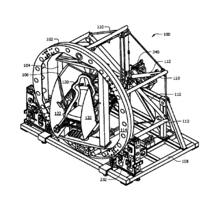
[0013] Figure 1 illustrates a front perspective view of one embodiment of the
three-
axis rotation device of the present invention;
[0014] Figure 2 illustrates a back perspective view of one embodiment of a
drive
system used for the three-axis rotation device of the present invention;
[0015] Figure 3 illustrates a bottom perspective view of one embodiment of a
drive
system used for the three-axis rotation device of the present invention;
[0016] Figure 4 illustrates a front perspective view of one embodiment of a
roll frame
of the three-axis rotation device of the present invention;
[0017] Figure 5 illustrates a front perspective view of one embodiment of a
yaw frame
of the three-axis rotation device of the present invention;
[0018] Figure 6 illustrates a perspective view of one embodiment of the seat
compartment of the three-axis rotation device of the present invention, with
the flaps open and
seat extended;
[0019] Figure 7 illustrates a perspective view of one embodiment of the seat
compartment of the three-axis rotation device of the present invention, with
the flaps closed and
seat retracted;
[0020] Figure 8 illustrates a frontal view of one embodiment of the seat
compartment
of the three-axis rotation device of the present invention, with the flaps
open;
[0021] Figure 9 illustrates a frontal view of one embodiment of the seat
compartment
of the three-axis rotation device of the present invention, with the flaps
closed;
[0022] Figure 10 depicts a perspective view of another embodiment of the three-
axis
rotation device of the present invention; and
[0023] Figure 11 depicts a top plan view of another embodiment of the three-
axis
rotation device of the present invention.
CA 02974677 2017-07-21
WO 2016/118455 PCT/US2016/013803
6
DETAILED DESCRIPTION
[0024] Figure 1 depicts a perspective view of one embodiment of the three-axis
human
rotation system 100 of the present invention. Generally, the system comprises
a roll frame 102, a
yaw frame 104 and a pitch frame 106. The pitch frame 106 is contained within
the yaw frame
104, and the yaw frame 104 is contained within the roll frame 102. The
language "contained
within" is intended to mean, for example, that when the yaw frame is rotated
around the yaw
axis, the pitch frame will also be rotated around the yaw axis. Of course, the
pitch frame can
also be rotated around the pitch axis at the same time as it is being rotated
around the yaw axis
by the yaw frame, or at a different time.
[0025] Additionally, the yaw frame being "contained within" the roll frame
means that
when the roll frame is rotated around the roll axis, the yaw frame will also
be rotated about the
roll axis. It should also be understood that because the pitch frame is
contained within the yaw
frame, the pitch frame will also be rotated around the roll axis along with
the yaw and roll
frames.
[0026] Each of the roll, yaw and pitch frames depicted in Figure 1 are capable
of being
rotated about different axes completely independently from one another, and
without any
limitation on the degree of rotation. One embodiment of a roll frame is
depicted in isolation in
Figure 4. As depicted in Figures 1 and 4, the roll frame 102 comprises a
generally annular truss
114 with axial support trusses 110 extending therefrom. The axial trusses are
generally parallel
to the roll axis of rotation, which the roll frame rotates around. A radial
truss 112 extends from
the side of each axial truss 110 opposite the side that is attached to the
annular truss 114. The
radial trusses extend radially from the roll axis of rotation. The radial
trusses 112 connect at
internal drive hub 240. The internal drive hub 240 is the location at which
the drive mechanisms
(described in more detail below) used to actuate the yaw and pitch frames pass
through the roll
frame.
[0027] The roll frame is supported on base 108. Base 108 comprises a support
frame
that has mounted on it at least one roll drive motor 230, which is connected
to drive wheel 232,
and the drive wheel 232 is in contact with the annular truss 114 of the roll
frame 102. Roll drive
motor 230 rotates the drive wheel 232 in either direction. Rotation of the
drive wheel 232 causes
the entire roll frame 102 to rotate about the roll axis, which generally runs
perpendicular to the
CA 02974677 2017-07-21
WO 2016/118455 PCT/US2016/013803
7
plane defined by the front face of annular truss 114, and runs through the
middle of internal drive
hub 240.
[0028] Figure 5 depicts one embodiment of a yaw frame 104 in isolation from
the
system. The yaw frame 104 is shown with a pitch frame torque transfer point
210, and pitch
frame drive actuator assembly 216, which is coupled to the yaw frame. The yaw
frame 104
houses at least a portion of the drive system (described in more detail below)
that is used to drive
the pitch frame 106 around the pitch axis. The yaw frame is rotated in the yaw
direction by a
yaw frame actuator (described in more detail below in conjunction with the
drive system overall)
that engages and is coupled to the yaw frame at location 224. The yaw axis of
rotation runs
through rotation points 210 and 224 depicted in Figure 5.
[0029] Figure 2 depicts a back perspective view of one embodiment of a drive
system
in isolation from the overall three-axis rotation system. This embodiment of
the drive system
comprises a roll drive motor 230 coupled to roll drive wheel 232. Roll drive
motor 230 is
capable of turning roll drive wheel 232 in both directions of rotation
(clockwise and
counterclockwise). The roll frame may also be supported by one or more passive
support wheels
234, which enable smooth operation of the system. To further ensure smooth
rotation of the roll
frame 102, the roll frame 102 may be encompassed by one or more
circumferential belts 250 that
engage the roll drive wheel 232. Such a circumferential drive belt around the
roll frame may
help compensate for any discontinuities in the roll frame circumference
introduced during the
roll frame manufacturing process, improve smooth movements for accelerations
and
decelerations, and improve the precision. In another embodiment, more than one
roll drive
motor and roll drive wheel are included in the system.
[0030] Figure 2 also depicts components that drive the yaw and pitch
rotational
directions. Yaw drive motor 204 drives an internal drive shaft that runs
through internal drive
hub 240, and rotates yaw drive belt 220. The yaw drive belt 220 is coupled to
yaw drive shaft
222, such that rotating yaw drive belt 220 in either direction of rotation
causes yaw drive shaft
222 to rotate in the same direction. Similarly, yaw drive shaft 222 is coupled
to the yaw frame
actuator at location 224. The yaw frame actuator translates the torque applied
to the yaw drive
shaft 222 approximately 90 through the use of various internal gears, as is
known in the art, and
applies that torque to the yaw frame. When all of the components of the yaw
drive system are
CA 02974677 2017-07-21
WO 2016/118455 PCT/US2016/013803
8
considered in their entirety, the yaw drive motor is capable of rotating the
yaw frame in both
directions of rotation around the yaw axis.
[0031] Also as depicted in Figure 2, the pitch drive motor 202 drives an
internal drive
shaft that runs through internal drive hub 240, which is coaxial with the
internal drive shaft that
drives the yaw drive belt. However, the pitch drive motor 202 is coupled with
the first pitch
drive belt 206, such that rotation of the pitch drive motor 202 causes
rotation of the first pitch
drive belt 206 in the same direction. First pitch drive belt 206 is coupled to
a first pitch drive
shaft 208, such that rotation of the first pitch drive belt 206 causes
rotation of the first pitch drive
shaft 208 in the same direction. The torque applied to the first pitch drive
shaft 208 by first pitch
drive belt 206 is translated approximately 90 through the use of various
internal gears at 210, as
is known in the art, to drive a second pitch drive shaft 212. As such, the
first pitch drive shaft
208 is coupled with the second pitch drive shaft 212, such that rotation of
the first pitch drive
shaft causes rotation of second pitch drive shaft. Second pitch drive shaft
212 is coupled to
second pitch drive belt 214. Finally, pitch frame actuator 216 is coupled to
second pitch drive
belt 214, such that rotation of the second pitch drive belt 214 in either
direction will
correspondingly cause rotation of the pitch frame actuator 216 about the pitch
axis. Figure 3
depicts a different perspective view of the drive system of Figure 2.
[0032] One inventive aspect of the system of the present invention lies in the
arrangement of the drive system. The drive system uniquely allows for rotation
of a human
subject seated in a seat attached to the pitch frame around three
perpendicular axes of rotation
completely independently of one another. Taking Figures 1 and 2 in
combination, it is seen that
the roll axis of rotation does not vary its orientation with respect to
gravity regardless of the
extent to which the roll frame is rotated about the roll axis, and regardless
of whether the yaw or
pitch drive systems are used. However, the use of drive belts 206 and 220,
which are
mechanically coupled to the various drive shafts and frame actuators of the
yaw and pitch drive
systems, allows for the roll frame to be rotated about the roll axis at any
orientation, and still
enable the yaw and pitch drive systems to operate. Similarly, the pitch drive
system allows for
the yaw frame to be rotated at any orientation with respect to the roll frame,
and still enable the
pitch drive system to rotate the pitch frame about the pitch axis. Such a
drive system is unknown
in the art and represents a marked improvement over prior art systems.
CA 02974677 2017-07-21
WO 2016/118455 PCT/US2016/013803
9
[0033] Some of the drive system components can be hidden within the various
frames
used in the overall system. For example, the second pitch drive shaft 212 and
second pitch drive
belt 214 can be hidden within the yaw frame 104 (depicted in Figure 5). Also,
the yaw drive
shaft 222 could be hidden within the roll frame 102, for example, within one
of the axial trusses
110.
[0034] The roll, yaw and pitch drive motors are controlled by a computer
system
operatively coupled to the drive motors. The position, angle of rotation, and
speed of the various
rotation frames are detected using one or a combination of sensors configured
for that purpose.
Preferably, sensors that detect the position, angle and speed of rotation for
each rotation frame
are embedded within, integral to, or in close proximity to the actuator for
the frame. The
computer system, or control module of the computer system, uses the positional
information in a
feedback, feed forward, or combination thereof scheme to execute the
positional and rotational
maneuvers and treatment methods described herein, or as desired by a
practitioner of the present
invention.
[0035] Figures 6 and 7 depict perspective views of one embodiment of the pitch
frame.
The pitch frame comprises a seat 120 configured for a human body affixed to
the pitch frame.
Generally, the seat will comprise a restraint mechanism, such as straps, belts
or harnesses, which
have been omitted from the figures for clarity. In one embodiment, the pitch
frame comprises
protective flaps 122. Protective flaps 122 are located on opposite sides of
the seat 120, and can
be connected to the pitch frame by a hinged connection, such that they are
able to rotate between
an open position (Figure 6) and a closed position (Figure 7). When the
protective flaps 122 are
in a closed position, a human subject sitting in seat 120 is prevented from
reaching extremities
(arms, legs, hands, etc.) outside the pitch frame, thereby preventing injury
to the human subject
during operation of the system. Also, in another embodiment, the seat 120 can
shift between an
extended position (Figure 6) and a retracted position (Figure 7). This feature
allows for an easier
ingress and egress for the human subject undergoing evaluation or treatment
within the system.
[0036] Figures 8 and 9 are frontal views of the embodiment of the pitch frame
106 and
seat assembly shown in Figures 6 and 7. The pitch axis of rotation runs
through rotation points
130. The pitch drive actuator can be coupled to the pitch frame at either of
these rotation points
130, with the other rotation point being passively rotationally coupled to the
yaw frame on the
opposite side.
CA 02974677 2017-07-21
WO 2016/118455
PCT/US2016/013803
[0037] Figure 10 depicts a perspective view of another embodiment of the three-
axis
rotation system of the present invention. As depicted therein, the roll frame
306 comprises an L-
shaped truss, which is rotated around the roll axis at 312 by a roll drive
motor 330. Contained
within the roll frame 306 is a C-shaped yaw frame 308, and contained within
the yaw frame 308
is a C-shaped pitch frame 310. The yaw frame 308 is rotated around the yaw
axis at 314 by a
yaw drive motor 302. The seat or chair 320 is affixed to/contained within the
pitch frame 310,
and rotates about the pitch axis at 316 when the pitch frame 310 is actuated
by the pitch drive
motor 304. The drive motors are coupled to their respective frames through one
or a
combination of drive belts and drive shafts, as described for the embodiment
discussed above.
The drive belts and shafts are depicted hidden within the respective roll, yaw
and pitch frames, as
described above. Also the placement of the drive motors shown in Figure 10 is
exemplary and
not by way of limitation. Figure 11 depicts a top plan view of another
embodiment of the L-C-C
frame assembly described above.
[0038] In a preferred embodiment, the roll frame can be raised and lowered to
allow
for easy access to the human subject being evaluated or treated. The L-shape
of the roll frame is
ideally suited for this purpose because the arm of the roll frame that
connects to the yaw frame
can be positioned above the chair, thereby providing unobstructed access to
the ground from the
chair.
[0039] The presently disclosed and claimed system allows a practitioner to
rotate a
human subject seated and restrained in the chair around three different axes
independently from
one another and without any restriction on the number of degrees of rotation.
Because each axis
of rotation can be programmed independently, an infinite number of position
orientations or
acceleration vectors can be applied to the human undergoing treatment. Prior
art systems are not
able to accomplish this.
[0040] This
capability will enable the practitioner to use the system for at least the
following purposes: proprioceptive therapy, vestibular therapy; visual/ocular
therapy; vestibular-
ocular reflex therapy; neuroplasticity/brain rewiring therapy; use of
centrifugal force to drive
blood flow/perfusion into specific parts of the brain as a therapy.
[0041] After assessing and quantifying a subject's brain function through a
diagnostic
process, specific rotational profiles can be created to stimulate,
rehabilitate, and optimize brain
function. By controlling the direction of rotation (+/- pitch, +/- roll, +/-
yaw), acceleration,
CA 02974677 2017-07-21
WO 2016/118455 PCT/US2016/013803
11
velocity, time duration, deceleration, static position of a single axis or two
axes while the other(s)
are rotating, and the combination of multiple axes of rotation into a single
profile, a practitioner
can target proprioceptive, vestibular, visual/ocular, vestibular-ocular
reflex, blood flow injection
by means of centrifugal force (induced perfusion), each as different
therapeutic strategies or
combinations of strategies.
[0042] In controlling the human subject's body (and head) rotation in
sequenced and
controlled movements, healthy neural pathways can be forged and reinforced
while causing the
atrophy of dysfunctional neural pathways. Sensory integration can be
recalibrated to enable
subjects to respond more accurately to their environment. By collecting
physiological data, the
system described and claimed herein is able to algorithmically respond with
methods to
accelerate the effectiveness of the therapy. Sequences of rotational movements
can be combined
to create complex therapy schemas. Visual image target(s) on a screen inside
the patient cabin
(pitch frame) can be passive or actively moving in any conceivable fashion to
coordinate the
rotational therapy with the planned sequences of eye movements relative to a
fixed head.
[0043] Conditions applicable to therapy include, without limitation:
performance
enhancement; brain injury; traumatic brain injury; stroke; concussion;
dementia; alzheimer's;
brain fogginess; dizziness; vertigo; postural orthostatic tachycardia
syndrome; cerebral palsy;
down syndrome; autism; balance/fall risk; spatial/depth vision issues;
dystonia; parkinson's;
post-traumatic stress disorder; central nervous system disorders; immune
system function as
modulated by the brain; digestive system function as modulated by the brain;
otolithic
stimulation therapy; otolithic-ocular reflex therapy.
[0044] The mechanical design of the present invention also employs a unique
drive
train system that differentiates it from the prior art. In particular, all of
the drive motors are
located outside the rotational space of the apparatus. The rotational space is
defined herein as
the entire volume of space that could be occupied by the roll, pitch and yaw
frames at all
orientations. Known rotational systems use drive motors for each rotational
axis that are
mounted in-line with the gear that drives the axis. For example, a
hypothetical prior art device
that utilized the yaw frame shown in Figure 5 would mount a motor in close
proximity to
location 224 to rotate the yaw frame about the yaw axis. This hypothetical
motor for such a prior
art device would thus be located within the rotational space of the apparatus.
In order to provide
the large amount of power needed by this motor contained within the rotational
space, a slip ring
CA 02974677 2017-07-21
WO 2016/118455 PCT/US2016/013803
12
would be required at the roll axis drive hub, and likely at the yaw axis drive
hub, because the
joints must allow for infinite rotation.
[0045] The problem with using slip rings to transmit high voltage or current
electricity
is that it introduces unwanted electromagnetic interference (EMI) into the
electrical system.
Minimization of EMI allows for maximum safety and efficiency of the system.
Known multi-
axis systems that use slip rings to power motors location within the
rotational space have been
observed to spontaneously move in directions that were not programmed. These
uncontrolled
movements are potentially very dangerous to the person undergoing treatment.
[0046] The present invention addresses this problem by using a combination of
belts
and shafts to transmit mechanical power from outside the rotational space
through the various
frames, eliminating the main source of EMI in known systems. This design
provides a novel
approach to administering continuous, independent three-axis rotation at a
level of safety and
reliability not achieved by known designs.
[0047] The 3-axis rotational device of the present invention has a number of
qualities
that make its clinical applications unique. Previous devices have not allowed
for simultaneous,
continuous three-axis rotation and positioning of a human subject. This
attribute of the rotational
chair allows for therapeutic customization that has not been achievable in
prior art designs.
Therapeutic interventions can be driven through the vestibular system, through
the visual system,
through activation of the proprioceptive system, and by increasing blood
perfusion to central
nervous system structures. Neural plasticity is the concept that the nervous
system adapts and
makes changes, either positively or negatively, based on changing demands of
the environment.
These changes and adaptations can be the result of typical interactions during
day-to-day life, as
a consequence of trauma or other neurodegenerative event, or through the
application of
rehabilitation strategies.
[0048] In order for neurons to function optimally in the nervous system, three
conditions must be met. Neurons must have oxygen, nutrition, and activation in
order to
maintain their connections to other neurons. Neurons must have an increase in
these three
factors in order to create new connections between neurons or repair damaged
connections.
Oxygen and nutrition are delivered to the neurons through the vascular system
and their delivery
is driven by the needs of the neuronal cell. A neuron uses axons and dendrites
to create synapses
with multiple other neurons at varying levels of proximity creating a network
of communication
CA 02974677 2017-07-21
WO 2016/118455 PCT/US2016/013803
13
fibers that allow cells to communicate locally and also with distal areas of
the body. Due to this
relationship a neuron can be stimulated by multiple connected neurons as they
are activated
throughout the body. These connected neurons may be linked to a peripheral
receptor or another
part of the central nervous system. As a neuron's activation is increased, it
will make additional
connections to other neurons in its network. If a neuron experiences a
decrease in activation, it
will begin to lose and breakdown connections to other neuronal networks.
[0049] The vestibular system of a human subject gives the individual a sense
of their
position in space and helps orient them to their environment. This system is
situated in the inner
ear bilaterally and is composed of two different sensory organs. The first is
the semicircular
canal system, which is composed of six semicircular canals. The canals are
oriented with three
canals on each side of the head with an orthogonal orientation to each other.
Each semicircular
canal is paired with a canal of opposite orientation on the other side. The
two horizontal canals
are oriented to sense rotations around the Z axis (vertical axis), the two
anterior canals are
oriented at 45 degrees to the anterior sagittal and coronal body planes and
detect rotations in the
vertical planes of motion, and the two posterior canals are oriented at 45
degree angles to the
posterior sagittal and coronal body planes and also detect angular motion in
the vertical plane.
The semicircular canals are filled with fluid and angular motion is detected
as this fluid puts
pressure on a sensory structure called the cupula. The cupula can emit an
excitatory signal or an
inhibitory signal that is sent to the brain depending on the direction it is
pushed. If a subject is
rotated to the right, the cupula in the right horizontal canal sends an
excitatory signal to the brain
and the cupula in the left horizontal canal sends an inhibitory signal. This
is the mechanism by
which all the semicircular canal pairings function.
[0050] The second sensory organ in the vestibular system is the otolithic
organ. The
otolithic system is located in the inner ear bilaterally and is connected with
the semicircular canal
system. The otolithic organ is composed of the utricle and the saccule and
senses linear
translation. The organ is composed of hair cells called stereocilia in a
gelatinous membrane that
is weighted by calcium carbonate crystals called otoliths. When the head is
placed in various
positions relative to gravity or a translational stimulation is administered,
the otoliths create a
shearing force on the stereocilia and generate either an excitatory or
inhibitory signal, which
propagates through central nervous system pathways. The utricle senses linear
accelerations and
head-tilt in the horizontal plane while the saccule detects linear
accelerations and head tilt in the
CA 02974677 2017-07-21
WO 2016/118455 PCT/US2016/013803
14
vertical plane. These signals are sent from the sensing structures of the
vestibular system and
integrate in multiple regions of the brain and brain stem for secondary
processing.
[0051] The visual system is utilized to observe the environment and generate
information that assists with balance, focus, and tracking. The visual system
typically utilizes
binocular vision with conjugate or coordinated eye movements to keep an object
of interest in
focus. Each eye has a retina, which contains light sensing cells that send
signals to the brain to
be interpreted as visual information. Within the retinal tissue is a structure
called the fovea that
is composed of light sensing cells responsible for color vision. In order to
maintain clear vision,
the visual system must be able to keep objects of interest focused on the
fovea and perform
proper and coordinated movements of the eyes to keep an object in view. When
the object of
interest changes position or if the point of interest changes, the visual
system must shift the fovea
to either maintain focus or move attention to a new target. The oculomotor
system assists in the
task of maintaining fovealization of a target through the use of a number of
eye movement
strategies. These eye movement strategies form the basis for steady vision and
rely on inputs
and integration of information from the vestibular system, proprioceptive
system, and other
senses to move the eyes appropriately.
[0052] The proprioceptive system is comprised of sensors that provide
information
about joint angle, muscle length, and muscle tension, which is integrated to
give information that
identifies where body parts are in space. The system is designed to give real-
time feedback
about the body's position in space and allow for appropriate actions to be
taken when variables
in the environment change. Skeletal muscle has two types of muscle responses,
volitional and
non-volitional. Volitional movements are voluntary movements of the body that
are under
conscious control and can be altered or planned by the individual. Non-
volitional movements
are involuntary movements that are reflexive within the body. Reflexive muscle
groups are
responsible for maintaining posture, adapting to perturbations experienced in
the environment,
and activating stabilizing musculature during volitional movements.
[0053] The vascular system of the body is designed to supply nutrients,
oxygen, and
other elements crucial for cellular survival throughout the body. When an
increased workload is
placed on a structure of the body, the vascular system will shunt blood to
these areas to assist
with the increased metabolic demand. As an example, when an individual uses a
muscle, like
performing a bicep curl, the vascular system will shunt blood to that muscle
to provide additional
CA 02974677 2017-07-21
WO 2016/118455 PCT/US2016/013803
support so the muscle can perform optimally. This helps the muscle to maximize
its strength and
adapt to added demand. The same mechanism is present with increased demand
during
activation of the central nervous system. When pathways within the nervous
system are
activated, more blood is shunted to those areas of activation to increase the
nutrients and oxygen
available for the neuronal cells.
[0054] The systems described above must work in concert with each other to
facilitate
optimal function of the nervous system. In order for a human subject to have
accurate and
appropriate perception and interaction with their environment, they must have
proper central
integration of information coming from the vestibular system, visual system,
and proprioceptive
system. During periods of movement and stimulation, proper blood flow must be
administered
to areas of activation of the nervous system as well as to the muscles of the
body. When these
systems do not work in concert, breakdowns in neurologic function occur.
During processes in
neurodegenerative diseases or traumatic brain injury there can be interruption
of the typical
pathways in the central nervous system that can cause inefficiencies in
communication between
areas of the brain and can distort the activation of the neuron and transport
of nutrients and
oxygen to parts of the brain that are in need of additional support. As these
processes progress,
there can be continued breakdown of neural pathways with continued aberrant
firing in these
neural networks. In order to address these breakdowns in neural communication,
stimulations
can be applied to neural pathways that are found to have aberrant firing.
These stimuli can be
applied through sensory receptors in the body including the vestibular system,
the visual system,
and the proprioceptive system. The 3-axis rotational device of the present
invention provides a
means of stimulating these pathways with a precision that has not been
available in previous
devices, due to its ability to rotate a human subject around three orthogonal
axes independently
from one another, simultaneously if desired.
[0055] When a disruption to the nervous system occurs, whether from trauma,
vascular
accident, neurodegenerative process, or developmental aberrancy, there can be
a breakdown in
central or peripheral nervous system pathways or in end organ sensors that
create a deficit in how
an individual perceives their world. When this occurs, the breakdown in these
pathways can be
quantified through physical examination and diagnostic testing. Once the
location of the lesion
has been identified, strategies can be implemented to stimulate and
rehabilitate those pathways or
the end organ receptors that are affected.
CA 02974677 2017-07-21
WO 2016/118455 PCT/US2016/013803
16
[0056] The 3-axis rotational device of the present invention allows for
stimulation of
multiple pathways that have peripheral and central consequences of
stimulation. These
stimulations can be tailored to address regions of the brain where aberrant
neuronal relationships
exist. By providing consistent stimulation in a controlled manner over time,
these pathways can
be adapted, retrained, and rehabilitated to function at their optimal
potential.
[0057] Off vertical axis rotation (OVAR) of a human subject activates
vestibulo-ocular
responses (VOR). The VOR is served by stimulation of receptors in the inner
ear that are
associated with reflex movements of the eyes as well as the neck and trunk.
The eye movements
are a result of a combination of receptor activation in the inner ear
(semicircular canal and otolith
components). Some eye movements occur with semicircular canal activation in
the planes of
these canals while others occur in the plane of gravity by stimulating the
otoliths.
[0058] OVAR is one of the few methods to evaluate and/or stimulate the
function of
otoliths. It has been used to quantify the maturation of the vestibular system
and the processes of
central compensation of the nervous system after vestibular injuries. OVAR is
a useful method
for clinically assessing both the otolith-ocular reflex and the semicircular
canal-otolith
interaction.
[0059] The positioning and rotational methods disclosed and claimed herein
involve a
computer-controlled chair that will rotate at a constant or variable velocity
about an axis that is
tilted with respect to the vector of gravity. The gravity vector can be
considered to be 90 degrees
to a level surface that is not tilted from a neutral position. As the chair
moves, the head of a
subject will be rotated about a tilted axis relative to the gravity vector,
unless only the yaw axis is
being rotated in an otherwise neutral (upright) position relative to gravity.
The vestibular system
has receptors that respond to gravitational forces. These receptors will be
activated sinusoidally
during rotation as the plane of the receptors changes with the change of the
gravity vector.
[0060] The movement of a human subject can be measured specific to rotations
and
translations around 3 primary orthogonal axes. The Z-axis runs from the base
of the feet up to
the head of the human subject and rotations around this axis are referred to
as yaw rotations. The
Y-axis is an axis that is parallel to one that runs between the ears of the
human subject and
rotations around this axis are referred to as pitch rotations. The X-axis runs
from the back of a
human subject through the front and rotations around this axis are referred to
as roll rotations.
CA 02974677 2017-07-21
WO 2016/118455 PCT/US2016/013803
17
The computer-controlled chair can be rotated in an infinite combination of
vectors around all
possible axes of human movement.
[0061] For example, it is possible to combine rotations in one plane while
simultaneously tilting the rotational axis in that plane or a combination of
some or all other
planes. This combination of OVAR results in eye movements in specific planes
that are
characterized with both slow and fast components specific to the axis
stimulated. The slow
component of eye movements has a mean velocity in the direction opposite to
the head rotation
and a sinusoidal modulation around the mean. Both the mean velocity and the
modulation
increase when the tilt angle and velocity of the chair movement occur.
[0062] OVAR in a combination of planes also results in changes of eye position
in the
orbit that compensate for head position changes when rotated. The mean slow
velocity of eye
movement is produced by a velocity storage mechanism in the vestibular system.
The velocity
storage system is well-studied and pathology in this system can be detected
and treated by
OVAR. The otolith organs induce compensatory eye position changes with regard
to gravity for
tilts in all planes (yaw, pitch and roll). These positional changes are
observed to indicate central
nervous system function and pathology.
[0063] OVAR in the three independent planes (X,Y,Z), which is enabled by the 3-
axis
device of the present invention, is the only mechanism to stimulate otolith
organs in challenging
gravitational postures. The 3-axis rotations will induce compensatory eye
position changes with
regard to gravity for tilts in the pitch, yaw and roll planes. Such
compensatory changes can be
utilized to examine and stimulate the function of the otolith organs. A
functional interpretation
of these results is that the combinations of fast and slow eye movements of
the VOR will attempt
to stabilize the image on the retina of one point of the surrounding world.
Subjects that have
difficulty in maintaining visual fixation on a target will benefit from this
therapy and
quantification of their function. Visual fixation on a steady target is
necessary to stand and walk
without falling. Falls are the largest cause of accidental death across all
age groups and are a
financial and emotional burden for society. The use of the 3-axis OVAR
computer-assisted chair
according to the present invention is specific to vestibular rehabilitation
and fall prevention.
Doses of stimulation and specificity of stimulation can be achieved in ways
not previously
achievable through use of previous OVAR devices.
CA 02974677 2017-07-21
WO 2016/118455 PCT/US2016/013803
18
[0064] The OVAR 3-axis chair of the present invention will allow physicians
and
therapists to change the representation of the gravity vector in a stereotaxic
axis. In one
embodiment, the chair is positioned such that the origin of the three axes X,
Y and Z is located
between the two labyrinths at the intersection of the frontal, sagittal and
horizontal planes. The
vector of gravity will be decomposed into its components along the 3 axes of
the chair. During
activation of the chair in a combination of axes, the gravity vector along the
X- and Y-axis will
vary sinusoidally while the gravity vector along the Z-axis will not vary in
time. The gravity
component that stimulates the brain is the sum of the gravity components along
each axis.
[0065] When a human subject looks straight ahead, he/she will look along the X-
axis
which is the intersection of the sagittal and horizontal planes. The Y-axis is
the axis that runs
between the ears at the junction of the horizontal and frontal planes while
the Z-axis is the
intersection of the frontal and sagittal planes. The OVAR 3-axis chair of the
present invention
will allow the operator to activate the otolithic system while decomposing the
gravity vector into
three components (X,Y,Z) each along one stereotaxic axis. The axes of rotation
while a human
subject is experiencing rotation will be approximately, in one embodiment,
around their center of
mass. When a human subject is rotated in the chair, the excitation level of
each cell in the
maculae of the saccule and utricle is proportional to the scalar product of
its polarization vector
and linear acceleration.
[0066] The polarization vectors for the otoliths are located in the
three planes (X,Y,Z),
with the utricle responding to horizontal gravity vectors in yaw and roll and
the saccule
responding to pitch axis rotations. As the human subject is rotated around
these axes there will
be extremes of gravitational stimulation occurring in a sinusoidal fashion.
When a human
subject is inverted, there will be maximum gravity vectors with the head in
the nose down
position and also in the upright position. Rotation around the yaw axis is not
associated with a
sinusoidal gravitational stimulation. Rotating a human subject in the roll
plane at a lateral tilt is a
major activator of the otolithic system and there are no canals in the roll
plane. The degree of
lateral tilt will increase the gravity vector in roll proportional to the
tilt. The 3-axis rotational
chair of the present invention can excite the sensory cells of the maculae
according to the
orientation of the polarization vector. This will allow the brain to integrate
rotational head
velocity and eye position to activate neurons in the velocity storage pathway
that is central to
brain function.
CA 02974677 2017-07-21
WO 2016/118455 PCT/US2016/013803
19
[0067] The 3-axis rotational device of the present invention can use the
vestibular
system as an access point to the central nervous system by stimulating the
semicircular canals
and otolithic organs with specificity and accuracy that has not been obtained
by prior art devices.
Directions of rotation can be manipulated to isolate pairings of semicircular
canals (i.e. rotation
stimulating the right anterior canal and inhibiting the left posterior canal)
or can be graded where
combinations of canals are stimulated by altering the vector of rotation by a
few degrees. This
function is useful in treating patients who have a deficit in a semicircular
canal pairing, however,
are unable to handle direct stimulation of those canals due to the fragile
state of their central
pathways. In this case, rotations can be initially biased in the direction of
healthy canals and the
stimulation vector can be slowly changed to incorporate more of the sensitive
canal system until
it can be stimulated directly. The 3-axis device of the present invention is
the first system to
allow this type of modification and control to vestibular inputs and
activation.
[0068] One embodiment of the present invention is a method for stimulating a
vestibular system in a human subject comprising: securing the human subject to
a chair, wherein
the chair is contained within: a pitch frame that rotates the chair about a
pitch axis, a yaw frame
that rotates the chair about a yaw axis, and a roll frame that rotates the
chair about a roll axis;
wherein the pitch, roll and yaw axes are orthogonal to each other, and
comprise an origin located
within the human subject; and stimulating at least one of an inner ear canal,
a utricle or a saccule
in the human subject by rotating the human subject independently around the
pitch, roll and yaw
axes. One example of a chair contained within the rotating frames is described
above. In
another embodiment, rotations caused by the rotating step are initially biased
towards a healthy
canal and then changed to increasingly incorporate a sensitive canal. It is
understood that
"rotating the human subject independently around the pitch, roll and yaw axes"
does not require
that all three axes of rotation be used simultaneously. For example, the human
subject may first
be rotated around the yaw axis a predetermined number of degrees and then the
yaw rotation
halted, after which the roll and pitch frames are actuated to rotate the human
subject along a
predetermined vector path. Other combinations of rotations are also included,
of course. This is
the case for all of the treatment methods described and claimed herein that
involve rotation of a
human subject around the three independent axes.
[0069] A similar treatment mechanism is present with activation of the central
nervous
system utilizing the visual system. As a human subject moves through their
environment, the
CA 02974677 2017-07-21
WO 2016/118455 PCT/US2016/013803
visual system uses a number of strategies to manage visual input and keep an
object of interest
steady on the fovea or focus attention to a new object of interest. These
strategies include gaze
holding, pursuit eye movements, saccadic eye movements, and optokinetic
nystagmus. Gaze
holding holds the eyes stationary when they are fixating on a target in the
field of vision. Pursuit
eye movements hold steady gaze on a target that is moving or when a human
subject is moving
in relationship to the target of interest. Saccadic eye movements are fast eye
movements that
refixate gaze on a new target of interest and optokinetic nystagmus is a
combination of slow and
fast eye movements that responds to shifts of the visual scene. Each of these
eye movements is
associated with specific regions and pathways in the brain. When there are
aberrancies in the
neuronal communications to these regions and along these pathways, significant
deficits occur in
the human subject's perception of the world and their ability to interact with
their environment.
The 3-axis chair of the present invention can be utilized to rehabilitate
these eye movement
deficits. By identifying the eye movements that are faulty and the location in
the visual field
where deficits are present, rotational strategies can be administered that
very specifically address
the problem areas. Prior art designs only gave the ability to address these
concerns when they
occur in certain planes, however, the 3-axis chair design of the present
invention allows for
rehabilitation strategies to be applied through any plane of eye movement
where there is a
deficit.
[0070] One embodiment of the present invention is a method for stimulating a
visual
system in a human subject comprising: securing the human subject to a chair,
wherein the chair
is contained within: a pitch frame that rotates the chair about a pitch axis,
a yaw frame that
rotates the chair about a yaw axis, and a roll frame that rotates the chair
about a roll axis; wherein
the pitch, roll and yaw axes are orthogonal to each other, and comprise an
origin located within
the human subject; and rotating the human subject independently around the
pitch, roll and yaw
axes while the human subject is fixating on a visual target of interest. In
another embodiment,
the visual target of interest is moving. In still another embodiment, the
visual target of interest is
stationary.
[0071] The proprioceptive system feeds information from the body back to the
brain
about the orientation of the muscles and joints in space. During a
developmental aberrancy,
neurodegenerative process or after a traumatic injury either to the brain or
to the body, irregular
signaling can occur through this system that creates motor deficits and
postural abnormalities
CA 02974677 2017-07-21
WO 2016/118455 PCT/US2016/013803
21
within the body. This can manifest as muscle hypertonicity, muscle
hypotonicity, or postural
distortions. These aberrant muscle firing patterns or postural distortions can
be quantified
through examination and regions of the brain or body of the human subject
where deficits exist
can be identified. Through the use of independent 3-axis rotation, as
disclosed herein, strategies
can be implemented that activate muscles that have become hypotonic, inhibit
musculature that
is hypertonic, or address postural deficits or abnormalities. The 3-axis
rotational device of the
present invention provides a means to administer this type of stimulation in
combinations that are
unique and appropriate for the proprioceptive deficiency that exists.
[0072] One embodiment of the present invention is a method for stimulating a
proprioceptive system in a human subject comprising: securing the human
subject to a chair,
wherein the chair is contained within: a pitch frame that rotates the chair
about a pitch axis, a
yaw frame that rotates the chair about a yaw axis, and a roll frame that
rotates the chair about a
roll axis; wherein the pitch, roll and yaw axes are orthogonal to each other,
and comprise an
origin located within the human subject; and stimulating the proprioceptive
system in the human
subject by rotating the human subject independently around the pitch, roll and
yaw axes.
[0073] The vascular blood supply to the brain is another system that will
benefit from
the ability to rotate a human subject in 3 independent axes of rotation. When
an area of the
human subject's body or brain becomes active, the nervous system will increase
the blood flow
to the tissues that facilitate that activity. If this activity continues over
time, the vascular system
will increase the quantum of vasculature in that region and provide more
oxygen and nutrients to
the cells. Within the central nervous system, the blood supply to the brain
facilitates proper
communication and maintenance of neuronal pathways. Neurodegenerative
conditions and
traumatic brain injury can have the opposite effect on blood supply to a
region of the brain.
Decreased blood flow and perfusion into pathways of the nervous system can
have detrimental
effects on the neurons in those networks. As a human subject is rotated in the
3-axis rotational
chair of the present invention, centrifugal forces will assist in driving
blood flow to the brain. In
order to increase blood flow to damaged or degraded regions of the brain and
nervous system,
consistent and appropriate stimulation must be applied to the affected
pathways over time to
increase activation of neurons and ultimately blood perfusion to those
tissues.
[0074] One embodiment of the present invention is a method for stimulating a
vascular
system in a human subject's brain comprising: securing the human subject to a
chair, wherein the
CA 02974677 2017-07-21
WO 2016/118455 PCT/US2016/013803
22
chair is contained within: a pitch frame that rotates the chair about a pitch
axis, a yaw frame that
rotates the chair about a yaw axis, and a roll frame that rotates the chair
about a roll axis; wherein
the pitch, roll and yaw axes are orthogonal to each other, and comprise an
origin located within
the human subject; and perfusing blood into a region of the brain by rotating
the human subject
independently around the pitch, roll and yaw axes.
[0075] The 3-axis rotational device disclosed herein is a therapeutic
intervention that
can accomplish this through the various receptors described previously. Having
the ability drive
therapies through one or various combinations of the vestibular system, the
visual system, the
proprioceptive system, and inducing blood flow with 3-axis rotation that is
specific to the deficits
that are present in those systems allows clinicians to provide treatments
tailored in ways not
available through previous designs.
[0076] Human subjects diagnosed or suspected of having neurological conditions
often
have dysfunction in different facets of neural processing. Some individuals
have inaccuracies in
the ability to detect and/or transfer sensory signals to be sent to central
processors. Others may
have difficulty in their ability to receive these signals and process them in
an accurate, timely
manner. Still others may have errors in converting sensory stimuli into
central integration to be
executed as accurate or appropriate movement, cognition, emotion or effect by
the individual.
Oftentimes people with neurological dysfunction have combinations of these
processing errors
that culminate in the conventional diagnostic criteria that are commonplace in
the practice of
health care.
[0077] Utilization of 3-axis rotation can be beneficial for those suffering
with these
types of disorders as the stimulation dosage and type may be manipulated to
adapt or modify
these errors in neural processing to improve the functionality of the system.
Implementing this
type of stimulation can be used to drive positive neuroplastic changes within
the central nervous
system.
[0078] Disorders that may benefit from this intervention include, but are not
limited to
the following classifications, based on the current nomenclature and
diagnostic criteria:
[0079] Balance disorders are a common manifestation of vestibular, visual, and
proprioceptive deficit. Stimulation of these systems can be utilized to
rehabilitate numerous
conditions that affect peripheral as well as central manifestations of these
disorders in human
subjects. Positive neuroplastic changes can be made through the use of 3-axis
rotation in these
CA 02974677 2017-07-21
WO 2016/118455 PCT/US2016/013803
23
cases. Some of these cases include: Dysequilibrium, Mal De Debarquement,
Motion-sickness,
Pre-syncope, and Vertigo.
[0080] Deficiencies of gaze and eye movements are very common signs of
dysfunction
in a number of pathological- and trauma-oriented conditions. Stimulation of
the vestibular and
oculomotor pathways can aid greatly in addressing the central issue causing
the ocular
dysfunction in a human subject. 3-axis rotation, as described herein, allows
for therapies to be
implemented that can specifically address the plane of aberrancy in which
these dysfunctions
occur. This is accomplished by rotating the individual through directions that
will stimulate
central visual and central vestibular pathways that correlate to the eye
movements where
pathology is present. Some of these conditions include: Convergence
Insufficiency,
Convergence Spasm, Diplopia, and Dysjunctive Eye Movements.
[0081] Developmental delay is a condition that affects millions of children in
the
United States and around the world. As the human body is early in development,
it uses stimuli
from its environment to mold and form its perception and understanding of the
world around it.
When a child misses establishment of specific connections in the brain,
significant delays or
deficits can arise that will hinder the child from engaging in an appropriate
or typical way.
Senses and systems like the vestibular system, the visual and oculomotor
system, and the
proprioceptive system can be used as access points to the central nervous
system to provide
increased stimulation to areas of the brain that are experiencing aberrant
development or delay.
This added stimulation can help increase integration of areas of the brain
connected to these
systems and drive developmental processes toward a more typical development
pathway. Some
of these conditions include: Alexia, Attention Deficit Hyperactivity Disorder
(ADD/ADHD),
Autism Spectrum Disorders, Dyslexia, Obsessive Compulsive Disorder (OCD),
Oppositional
Defiant Disorder (ODD), Pervasive Developmental Disorder (PDD)/Not Otherwise
Specified
(NOS), and Social Communication Disorder (SCD).
[0082] Dysautonomia is a condition where there is dysregulation of the
cardiovascular
system. This may manifest as irregularities, acceleration, or deceleration of
the heartbeat,
abnormal blood flow and perfusion to tissues in the body (peripheral and
central), and
hypersensitivity to touch. The cardiovascular system is regulated by central
nervous system
connections in the brain and brainstem. These regions have crossover
connections with regions
that integrate with the vestibular and proprioceptive system. By this
mechanism, 3-axis rotation
CA 02974677 2017-07-21
WO 2016/118455 PCT/US2016/013803
24
can make an impact therapeutically with this population of individuals. Some
conditions that
can be affected through this approach include: Cardiac Arrhythmia, Reflex
Sympathetic
Dystrophy, Reynaud's Phenomenon, and Tachycardia.
[0083] Movement disorders are highly prevalent conditions of human subjects
associated with neurological conditions that affect the speed, fluency,
quality, and ease of
movement. Abnormal fluency or speed of movement may involve excessive or
involuntary
movement (hyperkinesia) or slowed or absent voluntary movement (hypokinesia).
These
conditions affect the function of; and are consequences of aberrancies in the
visual, oculomotor,
vestibular and somatosensory systems of humankind. 3-axis rotation can be used
to drive
positive neuroplastic changes that can address these types of issues. Movement
disorders
include, but are not limited to: Abulia/dysbulia, Akinetic/Rigid Syndromes,
Aphasia/dysphasia,
Apraxia/dyspraxia, Ataxia/dystaxia, Bradykinetic Syndromes, Dyskinesias,
Dystonias,
Myoclonus, Spasticity, Stereotypic Movement Disorder, Tic/Tourette's Syndrome,
and Tremor.
[0084] Neurodegenerative disorders include a range of conditions that cause
damage
largely within the neurons of the brain and spinal cord. Degeneration of these
neurons can result
in the inability of different regions of the brain of a human subject to
operate and furthermore to
communicate with other regions and pathways of the brain. The effects are far-
reaching and
though the function of one area of the brain may not be directly related to
another area, damage
in the shared communication networks can provide a mechanism for massive
functional loss.
While neurodegenerative conditions cause damage to neurons that may be
irreplaceable,
surviving neurons may provide alternative communication pathways through
creation of new
connections to other neuronal networks (synaptogenesis). 3-axis rotation is a
powerful means to
drive this connectivity. Some neurodegenerative disorders that can be treated
by 3-axis rotation
include: Alzheimer's Disease, Coritcobulbar Degeneration, Dementia, Multiple
Sclerosis,
Multiple System Atrophy, Parkinson's Disease / Parkinson-Plus / Atypical
Parkinson's, and
Supranuclear Palsy.
[0085] Orthostatic intolerance is a condition where specific positions of the
human
body cause excessive increases, decreases, or fluctuations in blood pressure
or heart rate. As a
human subject moves from a lying position or seated position to a standing
position, the brain
will sense a drop in blood pressure through baroreceptors or a change in
position through the
otolithic system and make compensatory changes to keep blood perfusion to the
entire body as
CA 02974677 2017-07-21
WO 2016/118455 PCT/US2016/013803
constant and consistent as possible. In a human subject who has sustained a
bodily injury which
affects this system, it can cause extreme shifts of blood pressure or heart
rate. One mechanism to
rehabilitate this system is the use of vestibular input through the otolithic
system to recalibrate
the system so that changes of position do not elicit an aberrant response from
the body. The 3-
axis rotational device is a means of providing this stimulation in a manner
that is specific to the
injury that has occurred. Some of these conditions include: Orthostatic
Hypotension and
Positional Orthostatic Tachycardic Syndrome (POTS).
[0086] Pain syndromes include those conditions associated with abnormal
perception
of nociception, leading to suffering in a human subject. Pain is a complex
phenomenon that has
a multitude of origins. Pain as a central consequence is problematic for human
subjects as well
as healthcare providers in the sense that the pain generator is due to a
faulty perception of
sensory stimuli. This perception occurs as an inaccuracy in central processing
within the brain.
These central processing systems have shared neural networks with the systems
that are
influenced by the stimulation associated with multiple axis rotation. In this
sense, 3-axis rotation
can be used in a therapeutic approach to decrease the impact of these types of
conditions. Pain
syndromes include, but are not limited to: Cervicalgia, Cluster Headache,
Complex Regional
Pain Syndrome (CRPS), Headache, Lumbalgia, Migraine, Temperomandibular Joint
Disorder,
Thoracalgia, and Trigeminal Neuralgia.
[0087] Traumatic brain injury is a condition that can have profound impact on
the
nervous system and sensing organs of a human subject. Traumatic injury can
occur to in any
region of the brain. The systems affected can be wide-ranging or focal in
their distribution or
presentation. When these deficits are quantified, a determination of the
regions of the brain
affected can be made. If the injury affects the vestibular system, visual
system, oculomotor
system, somatosensory system, the vascular system, or any system in
communication with these
systems, a therapy regimen utilizing 3-axis rotation may be used to
rehabilitate the damaged
areas of the brain. Some of these conditions include: Centrally-maintained
Vestibulopathy,
Mild/Moderate/Severe Traumatic Brain Injury, Post-concussive Syndrome and
Stroke.
[0088] While the invention is susceptible to various modifications and
alternative
forms, specific embodiments thereof have been shown by way of example in the
drawings and
are herein described in detail. It should be understood, however, that the
description herein of
specific embodiments is not intended to limit the invention to the particular
forms disclosed.