Note: Descriptions are shown in the official language in which they were submitted.
84031647
Downhole Cutting and Sealing Apparatus
Cross-Reference to Related Applications
[0001] This application claims priority to U.S. Application No. 62/108,393,
titled
"METHOD OF ACTIVATING A EUTECTIC MATERIAL FOR WELLBORE
APPLICATIONS WITH A LASER," Attorney Docket No. IS15.0134-US-PSP, filed
January 27, 2015.
Background of the Disclosure
[0002] The present disclosure is related in general to wellsite equipment,
such as oilfield
surface equipment, downhole assemblies, coiled tubing (CT) assemblies,
slickline assemblies,
and the like. The present disclosure is also related to the use of laser
cutting equipment and
sealing materials for repairing or sealing completion tabulars and other
conduits located
within a wellbore and/or for repairing or sealing portions of rock formation
around the
wellbore.
[0003] Coiled tubing is a technology that has been expanding its range of
application
since its introduction to the oil industry in the 1960's. Its ability to pass
through the
completion tubulars and the wide array of tools and technologies that may be
used in
conjunction with it make coiled tubing a versatile technology. Typical coiled
tubing
apparatus include surface pumping facilities, a coiled tubing string mounted
on a reel, a
method to convey the coiled tubing into and out of the wellbore (such as an
injector head or
the like), and surface control apparatus at the wellhead. Coiled tubing has
been utilized for
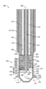
performing well treatment and/or well intervention operations in existing
wellbores, such as,
but not limited to, hydraulic fracturing, matrix acidizing, milling,
perforating, coiled tubing
drilling, and the like.
Summary of the Disclosure
[0004] This summary is provided to introduce a selection of concepts that
are further
described below in the detailed description. This summary is not intended to
identify
1
Date Recue/Date Received 2021-02-10
84031647
indispensable features of the claimed subject matter, nor is it intended for
use as an aid in
limiting the scope of the claimed subject matter.
[0005] The present disclosure introduces an apparatus that includes a
downhole tool for
conveyance within a tubular secured in a wellbore extending into a
subterranean formation.
The downhole tool includes: a laser apparatus operable to cut a slot in the
tubular; and a
sealing material. The downhole tool is operable to provide melted sealing
material within the
slot.
[0006] The present disclosure also introduces an apparatus that includes a
downhole tool
for conveyance within a tubular secured within a wellbore extending into a
subterranean
formation. The downhole tool includes: a laser apparatus operable to form a
slot along the
tubular; a sealing material; and a spreader operable to direct the sealing
material into the slot.
The downhole tool is operable to melt the sealing material within the slot.
[0007] The present disclosure also introduces a method that includes
conveying a laser
apparatus within a tubular secured within a wellbore extending into a
subterranean formation.
The laser apparatus is operated to form a slot along the tubular. A sealing
material is
conveyed within the tubular. A melted sealing material is provided within the
slot such that
the melted sealing material seals the slot upon solidification.
[0007a] Some embodiments disclosed herein provide an apparatus comprising: a
downhole
tool for conveyance within a tubular secured in a wellbore extending into a
subterranean
formation, wherein the downhole tool comprises: a laser apparatus operable to
cut a slot in the
tubular, the laser apparatus comprising: a housing; a deflector operable to
rotate to direct a
laser beam upon a predetermined portion of a side surface of the tubular; and
a motor operable
to rotate the deflector; and a sealing material, wherein the sealing material
is disposed at least
partially about the housing, and wherein at least one of the deflector and the
sealing material
is axially movable with respect to the other to direct the laser beam upon the
sealing material
to melt the sealing material; wherein the downhole tool is operable to provide
the sealing
material, in a melted state, within the slot and to provide a path for flowing
the sealing
material from the downhole tool and into the slot.
10007b1 Some embodiments disclosed herein provide an apparatus comprising: a
downhole
tool for conveyance within a tubular secured in a wellbore extending into a
subterranean
formation, wherein the downhole tool comprises: a laser apparatus operable to
cut a slot in the
2
Date Recue/Date Received 2021-08-03
84031647
tubular; and a sealing material; wherein the downhole tool is operable to
provide the sealing
material, in a melted state, within the slot and to provide a path for flowing
the sealing
material from the downhole tool and into the slot; and wherein the downhole
tool comprises a
housing having a downhole portion comprising a first outer diameter that is
larger than a
second outer diameter of an uphole portion of the downhole tool, and wherein a
surface
transitioning between the first and second outer diameters defines a spreader
that urges the
sealing material into the slot.
[0007c] Some embodiments disclosed herein provide an apparatus comprising: a
downhole
tool for conveyance within a tubular secured in a wellbore extending into a
subterranean
formation, wherein the downhole tool comprises: a laser apparatus operable to
cut a slot in the
tubular; and a sealing material; wherein the downhole tool is operable to
provide the sealing
material, in a melted stat, within the slot and to provide a path for flowing
the sealing material
from the downhole tool and into the slot; and wherein the downhole tool
further comprises a
spreader disposed downhole from the sealing material, wherein the spreader is
movable
between a retracted position and an expanded position, wherein in the
retracted position the
spreader comprises a first outer diameter, wherein in the expanded position
the spreader
comprises a second outer diameter that is larger than the first outer
diameter, and wherein in
the expanded position the spreader urges the sealing material radially outward
toward a side
surface of the tubular.
[0007d] Some embodiments disclosed herein provide an apparatus comprising: a
downhole
tool for conveyance within a tubular secured in a wellbore extending into a
subterranean
formation, wherein the downhole tool comprises: a laser apparatus operable to
cut a slot in the
tubular, and a sealing material; wherein the downhole tool is operable to
provide the sealing
material, in a melted state, within the slot and to provide a path for flowing
the sealing
material from the downhole tool and into the slot; wherein the downhole tool
is conveyable
within the tubular via coiled tubing operable to communicate a fluid from a
wellsite surface
from which the wellbore extends to the downhole tool, and wherein the downhole
tool further
comprises a nozzle operable to direct the fluid into the slot; and wherein the
laser apparatus is
operable to direct a laser beam along a first radial path while cutting the
slot, and wherein the
nozzle is operable to direct the fluid along a second radial path that at
least partially overlaps
the first radial path.
2a
Date Recue/Date Received 2021-08-03
84031647
[0007e] Some embodiments disclosed herein provide a method comprising:
conveying a
laser apparatus within a tubular secured within a wellbore extending into a
subterranean
formation; operating the laser apparatus to form a slot along the tubular;
conveying a sealing
material within the tubular; and providing the sealing material within the
slot such that the
sealing material, when melted, seals the slot upon solidification, wherein the
laser apparatus is
configured to provide a path for the melted sealing material; and wherein
providing the melted
sealing material within the slot comprises utilizing a spreader.
[0008] These and additional aspects of the present disclosure are set forth
in the
description that follows, and/or may be learned by a person having ordinary
skill in the art by
reading the materials herein and/or practicing the principles described
herein. At least some
aspects of the present disclosure may be achieved via means recited in the
attached claims.
Brief Description of the Drawings
[0009] The present disclosure may be understood from the following detailed
description
when read with the accompanying figures. It is emphasized that, in accordance
with the
standard practice in the industry, various features are not drawn to scale. In
fact, the
dimensions of the various features may be arbitrarily increased or reduced for
clarity of
discussion.
[0010] FIG. 1 is a schematic view of at least a portion of an example
implementation of
apparatus according to one or more aspects of the present disclosure.
[0011] FIG. 2 is a schematic sectional view of at least a portion of an
example
implementation of the apparatus shown in FIG. 1 according to one or more
aspects of the
present disclosure.
[0012] FIG. 3 is a schematic view of at least a portion of an example
implementation of
apparatus according to one or more aspects of the present disclosure.
[0013] FIGS. 4 and 5 are schematic sectional views of the apparatus shown
in FIG. 2
during different stages of operation according to one or more aspects of the
present disclosure.
2h
Date Recue/Date Received 2021-08-03
CA 02974703 2017-07-21
WO 2016/123166 PCT/US2016/015026
[0014] FIG. 6 is an axial view of the apparatus shown in FIG. 5 according
to one or more
aspects of the present disclosure.
[0015] FIGS. 7-13 are schematic sectional views of the apparatus shown in
FIG. 2 during
different stages of operation according to one or more aspects of the present
disclosure.
Detailed Description
[0016] It is to be understood that the following disclosure provides many
different
embodiments, or examples, for implementing different features of various
embodiments
Specific examples of components and arrangements are described below to
simplify the present
disclosure. These are, of course, merely examples and are not intended to be
limiting. In
addition, the present disclosure may repeat reference numerals and/or letters
in the various
examples. This repetition is for simplicity and clarity, and does not in
itself dictate a relationship
between the various embodiments and/or configurations discussed. Moreover, the
formation of a
first feature over or on a second feature in the description that follows may
include embodiments
in which the first and second features are formed in direct contact, and may
also include
embodiments in which additional features may be formed interposing the first
and second
features, such that the first and second features may not be in direct
contact.
[0017] FIG. 1 is a schematic view of at least a portion of an example
wellsite system 100
according to one or more aspects of the present disclosure, representing an
example coiled tubing
environment in which one or more apparatus described herein may be
implemented, including to
perform one or more methods and/or processes also described herein. However,
it is to be
understood that aspects of the present disclosure are also applicable to
implementations in which
wireline, slickline, and/or other conveyance means are utilized instead of or
in addition to coiled
tubing.
[0018] FIG. 1 depicts a wellsite surface 105 upon which various wellsite
equipment is
disposed proximate a wellbore 120. FIG. 1 also depicts a sectional view of the
Earth below the
wellsite surface 105 containing the wellbore 120, as well as a tool string 110
positioned within
the wellbore 120. The wellbore 120 has a sidewall 121 and extends from the
wellsite surface
105 into one or more subterranean formations 130. When utilized in cased-hole
implementations, a cement sheath 124 may secure a casing 122 within the
wellbore 120.
However, one or more aspects of the present disclosure are also applicable to
open-hole
implementations, in which the cement sheath 124 and the casing 122 have not
yet been installed
3
CA 02974703 2017-07-21
WO 2016/123166 PCT/US2016/015026
in the wellbore 120. The wellbore 120 may further include a
completion/production tubular 114,
which may be disposed within the casing 122.
[0019] At the wellsite surface 105, the wellsite system 100 may comprise a
control and
power center 180 (referred to hereinafter as a "control center") comprising
processing and
communication equipment operable to send, receive, and process electrical
and/or optical control
signals to control at least some aspects of operations of the wellsite system
100. The control
center 180 may also provide electrical power and communicate the control
signals via electrical
conductors 181, 182, 183 extending between the control center 180 and a laser
source 190, a
laser generator chiller 185, and the tool string 110 positioned within the
wellbore 120. The laser
source 190 may provide energy in the form of a laser beam to at least a
portion of the tool string
110. The laser source 190 may provide the laser beam to the tool string 110
via an optical
conductor 191, which may comprise one or more fiber optic cables.
[0020] The electrical conductor 181 may comprise a plurality of conduits or
conduit portions
interconnected in series and/or in parallel between the control center 180 and
the tool string 110.
For example, as depicted in the example implementation of FIG. 1, the
electrical conductor 181
may comprise a stationary portion extending between the control center 180 and
a reel 160 of
coiled tubing 161, such that the stationary portion of the electrical
conductor 181 remains
substantially stationary with respect to the wellsite surface 105 during
conveyance of the tool
string 110. The electrical conductor 181 further comprises a moving portion
extending between
the reel 160 and the tool string 110 via the coiled tubing 161, including the
coiled tubing 161
spooled on the reel 160. Thus, the moving portion of the electrical conductor
181 may rotate and
otherwise move with respect to the wellsite surface 105 during the conveyance
of the tool string
110.
[0021] Similarly, the optical conductor 191 may comprise a plurality of
conduits or conduit
portions interconnected in series and/or in parallel between the laser source
190 and the tool
string 110. For example, as depicted in the example implementation of FIG. 1,
the optical
conductor 191 may comprise a stationary portion extending between the laser
source 190 and the
reel 160 of the coiled tubing 161, such that the stationary portion of the
optical conductor 191
remains substantially stationary with respect to the wellsite surface 105
during the conveyance of
the tool string 110. The optical conductor 191 may further comprise a moving
portion extending
between the reel 160 and the tool string 110 via the coiled tubing 161,
including the coiled tubing
161 spooled on the reel 160. Thus, the moving portion of the optical conductor
191 may rotate
4
CA 02974703 2017-07-21
WO 2016/123166 PCT/US2016/015026
and otherwise move with respect to the wellsite surface 105 during the
conveyance of the tool
string 110. A swivel or rotary joint 163, such as may be known in the art as a
collector, provides
an interface between the stationary and moving portions of the electrical and
optical conductors
181, 191.
[00221 The wellsite system 100 may further comprise a fluid source 140 from
which a fluid
(referred to hereinafter as a "surface fluid") may be communicated by a fluid
conduit 141 to the
reel 160 of the coiled tubing 161 and/or other conduits that may be deployed
into the wellbore
120. The fluid conduit 141 may be fluidly connected with the coiled tubing 161
by, for example,
a swivel or another rotating coupling (obstructed from view). The coiled
tubing 161 may be
operable to communicate the surface fluid received from the fluid source 140
to the tool string
110 coupled at a downhole end of the coiled tubing 161.
[0023] The coiled tubing 161 may be further operable to transmit or convey
therein the
moving portions of the optical and/or electrical conductors 181, 191 from the
wellsite surface
105 to the tool string 110. The electrical and optical conductors 181, 191 may
be disposed
within an internal passage of the coiled tubing 161 inside a protective metal
carrier (not shown)
to insulate and protect the conductors 181, 191 from the surface fluid inside
the coiled tubing
161. However, the optical and/or electrical conductors 181, 191 may also or
instead be secured
externally to the coiled tubing 161 or embedded within the structure of the
coiled tubing 161.
The reel 160 may be rotationally supported on the wellsite surface 105 by a
stationary base 164,
such that the reel 160 may be rotated to advance and retract the coiled tubing
161, including the
electrical and optical conductors 181, 191, within the wellbore 120, such as
during the
conveyance of the tool string 110 within the wellbore 120.
[0024] The wellsite system 100 may further comprise a support structure
170, such as may
include a coiled tubing injector 171 and/or other apparatus operable to
facilitate movement of the
coiled tubing 161 in the wellbore 120. Other support structures, such as a
derrick, a crane, a
mast, a tripod, and/or other structures, may also or instead be included. A
diverter 172, a blow-
out preventer (BOP) 173, and/or a fluid handling system 174 may also be
included as part of the
wellsite system 100. For example, during deployment, the coiled tubing 161 may
be passed from
the injector 171, through the diverter 172 and the BOP 173, and into the
wellbore 120.
[0025] The tool string 110 may be conveyed along the wellbore 120 via the
coiled tubing
161 in conjunction with the coiled tubing injector 171, which may be operable
to apply an
adjustable uphole and downhole force to the coiled tubing 161 to advance and
retract the tool
CA 02974703 2017-07-21
WO 2016/123166 PCT/US2016/015026
string 110 within the wellbore 120. Although FIG. 1 depicts a coiled tubing
injector 171, it is to
be understood that other means operable to advance and retract the tool string
110, such as a
crane, a winch, a draw-works, a top drive, and/or other lifting device coupled
to the tool string
110 via the coiled tubing 161 and/or other conveyance means (e.g., wireline,
drill pipe,
production tubing, etc.), may also or instead be included as part of the
wellsite system 100.
[00261 During some downhole operations, the surface fluid may be conveyed
through the
coiled tubing 161 and caused to exit into the wellbore 120 adjacent to the
tool string 110. For
example, in the open-hole implementation, the surface fluid may be directed
into an annular area
between the sidewall 121 of the wellbore 120 and the tool string 110 through
one or more ports
or nozzles (not shown) in the coiled tubing 161 and/or the tool string 110.
However, in the
cased-hole implementation, the surface fluid may be directed into an annular
area between an
inner surface 123 and the tool string 110 through one or more ports or nozzles
in the coiled
tubing 161 and/or the tool string 110. The inner surface 123 may be an inner
surface of the
casing 122 or an inner surface of the completion/production tubular 114, if
disposed within the
casing 122. Thereafter, the surface fluid and/or other fluids may return in
the uphole direction
and out of the wellbore 120. The diverter 172 may direct the returning fluid
to the fluid handling
system 174 through one or more conduits 176. The fluid handling system 174 may
be operable
to clean the returning fluid and/or prevent the returning fluid from escaping
into the
environment. The returned fluid may then be directed to the fluid source 140
or otherwise
contained for later use, treatment, and/or disposal.
[00271 The tool string 110 may comprise one or more modules, sensors,
and/or tools 112,
hereafter collectively referred to as the tools 112. For example, one or more
of the tools 112 may
be or comprise at least a portion of a monitoring tool, an acoustic tool, a
density tool, a drilling
tool, an electromagnetic (EM) tool, a formation testing tool, a fluid sampling
tool, a formation
logging tool, a formation measurement tool, a gravity tool, a magnetic
resonance tool, a neutron
tool, a nuclear tool, a photoelectric factor tool, a porosity tool, a
reservoir characterization tool, a
resistivity tool, a seismic tool, a surveying tool, a tough logging condition
(TLC) tool, a plug,
and/or one or more perforating guns and/or other perforating tools, among
other examples within
the scope of the present disclosure.
[00281 One or more of the tools 112 may be or comprise a casing collar
locator (CCL)
operable to detect ends of casing collars by sensing a magnetic irregularity
caused by the
relatively high mass of an end of a collar of the casing 122. One or more of
the tools 112 may
6
CA 02974703 2017-07-21
WO 2016/123166 PCT/US2016/015026
also or instead be or comprise a gamma ray (GR) tool that may be utilized for
depth correlation.
The CCL and/or GR tools may transmit signals in real-time to wellsite surface
equipment, such
as the control center 180, via the electrical conductor 181 or another
communication means. The
CCL and/or GR tool signals may be utilized to determine the position of the
tool string 110
and/or selected portions of the tool string 110, such as with respect to known
casing collar
numbers and/or positions within the wellbore 120. Therefore, the CCL and/or GR
tools may be
utilized to detect and/or log the location of the tool string 110 within the
wellbore 120, such as
during downhole operations described below.
[0029] One or more of the tools 112 may also comprise one or more sensors
113. The
sensors 113 may include inclination and/or other orientation sensors, such as
accelerometers,
magnetometers, gyroscopic sensors, and/or other sensors for utilization in
detemiining the
orientation of the tool string 110 relative to the wellbore 120. The sensors
113 may also or
instead include sensors for utilization in determining petrophysical and/or
geophysical
parameters of a portion of the formation 130 along the wellbore 120, such as
for measuring
and/or detecting one or more of pressure, temperature, strain, composition,
and/or electrical
resistivity, among other examples within the scope of the present disclosure.
The sensors 113
may also or instead include fluid sensors for utilization in detecting the
presence of fluid, a
certain fluid, or a type of fluid within the tool string 110 or the wellbore
120. The sensors 113
may also or instead include fluid sensors for utilization in measuring
properties and/or
determining composition of fluid sampled from the wellbore 120 and/or the
formation 130, such
as spectrometers, fluorescence sensors, optical fluid analyzers, density
sensors, viscosity sensors,
pressure sensors, and/or temperature sensors, among other examples within the
scope of the
present disclosure.
[0030] The wellsite system 100 may also include a telemetry system
comprising one or more
downhole telemetry tools 115 (such as may be implemented as one or more of the
tools 112)
and/or a portion of the control center 180 to facilitate communication between
the tool string 110
and the control center 180. The telemetry system may be a wired electrical
telemetry system
and/or an optical telemetry system, among other examples.
[0031] The tool string 110 may also include a downhole tool 200 operable to
repair tubular
members downhole, such as the casing 122 and/or the completion/production
tubular 114, which
may be disposed within the casing 122. The downhole tool 200 may be further
operable to repair
a portion of the cement sheath 124 securing the casing 122 within the wellbore
120. The
7
CA 02974703 2017-07-21
WO 2016/123166 PCT/US2016/015026
downhole tool 200 may also be operable to repair a portion of the subterranean
formation 130
surrounding or defining the wellbore 120 in both the cased-hole and open-hole
implementations.
For example, the downhole tool 200 may be operable to smooth out, patch, plug,
or otherwise
repair holes, perforations, scrapes, deformations, and other damaged portions
along the sidewall
121 in an open-hole implementation and/or the inner surface 123 in a cased-
hole implementation,
including damage to the completion/production tubular 114, the casing 122, the
cement sheath
124, and/or the formation 130 surrounding the wellbore 120. The downhole tool
200 may
comprise alaser cutting apparatus operable to direct the laser beam upon the
damaged portions
along the sidewall 121 and/or the inner surface 123 to remove or cut the
damaged portion by
forming one or more radially extending cavities or slots (referred to
hereinafter as "radial slots")
along the damaged portion. The radial slots (shown in and identified in FIGS.
5-7 with numeral
286) may extend through or penetrate the completion/production tubular 114,
the casing 122, the
cement sheath 124, and/or the formation 130 a predetermined depth.
[0032] Although FIG. 1 shows the tool string 110, including the downhole
tool 200, disposed
within a vertical portion of the wellbore 120 to form the radial slots
extending outwardly along a
substantially horizontal plane, it is to be understood that the downhole tool
200 may also be
utilized to form the radial slots in a horizontal or partially deviated
portion of the wellbore 120.
Accordingly, the radial slots may also be formed along a plane extending
substantially vertically
or diagonally with respect to the wellsite surface 105.
[0033] The tool string 110 is further shown in connection with the optical
conductor 191 and
the electrical conductor 181, which may extend through at least a portion of
the tool string 110,
including the downhole tool 200. The optical conductor 191 may be operable to
transmit the
laser beam from the laser source 190 to the downhole tool 200, whereas the
electrical conductor
181 may be operable to transmit the electrical control signals and/or the
electrical power between
the control center 180 and the tool string 110, including the downhole tool
200.
[00341 The electrical conductor 181 may also permit electrical
communication between the
several portions of the tool string 110 and may comprise various electrical
connectors and/or
interfaces (not shown) for electrical connection with the several portions of
the tool string 110.
Although the electrical conductor 181 is depicted in FIG. 1 as a single
continuous electrical
conductor, the wellsite system 100 may comprise a plurality of electrical
conductors (not shown)
extending along the coiled tubing 161 and/or the tool string 110. Also,
although FIG. 1 depicts
the downhole tool 200 being coupled at a downhole end of the tool string 110,
the downhole tool
8
CA 02974703 2017-07-21
WO 2016/123166 PCT/US2016/015026
200 may be coupled between the tools 112, or further uphole in the tool string
110 with respect
to the tools 112. The tool string 110 may also comprise more than one instance
of the downhole
tool 200, as well as other apparatus not explicitly described herein.
[0035] FIG. 2 is schematic sectional view of at least a portion of an
example implementation
of the downhole tool 200 shown in FIG. 1 according to one or more aspects of
the present
disclosure. The following description refers to FIGS. 1 and 2, collectively.
[0036] The downhole tool 200 comprises a laser cutting apparatus 202
operable to receive a
laser beam 252 from the laser source 190 and direct the laser beam 252 upon
the sidewall 121 of
the wellbore 120 in the open-hole implementation or the inner surface 123 of
the
completion/production tubular 114 or the casing 122 in the cased-hole
implementation to remove
the damaged portion of the sidewall 121 or the inner surface 123 designated
for repair.
Accordingly, the laser cutting apparatus 202 may cut one or more radial slots
along the damaged
portion of the sidewall 121 or the inner surface 123, such as may extend into
or through the
completion/production tubular 114, the casing 122, the cement sheath 124,
and/or the formation
130 around the wellbore 120.
[0037] The laser cutting apparatus 202 includes a housing 210, which
defines an internal
space 205 and a fluid pathway 214 within the downhole tool 200. The housing
210 may
comprise a lower housing 211 and an upper housing 212. The upper housing 212
may couple the
downhole tool 200 with one of the tools 112 of the tool string 110 and/or with
the coiled tubing
161, such as may facilitate communication of the surface fluid, the electrical
power, the electrical
signals, and/or the laser beam 252 to the downhole tool 200. For example, the
upper housing
212 may be operable to receive therein or couple with the coiled tubing 161,
such as to permit
communication of the surface fluid from the fluid source 140 to the downhole
tool 200. The
upper housing 212 may be further operable to receive therein the electrical
conductor 181, such
as to permit communication of the electrical power and/or signals from the
control center 180 to
the downhole tool 200. The upper housing 212 may also be operable to receive
therein or couple
with the optical conductor 191, such as to facilitate transmission of the
laser beam 252 from the
laser source 190 to the downhole tool 200.
[0038] The lower housing 211 may be rotationally coupled with the upper
housing 212 in a
manner permitting the lower housing 211 to rotate relative to the upper
housing 212, such as
about an axis of rotation 251, which may substantially coincide with a
longitudinal central axis
203 of the downhole tool 200. The lower housing 211 may be disposed at a
downhole end of the
9
CA 02974703 2017-07-21
WO 2016/123166 PCT/US2016/015026
downhole tool 200, and may comprise a bowl-shaped or other configuration
having an open end
217 and a closed end 216. The open end 217 may be rotationally engaged or
otherwise coupled
with the upper housing 212, such as to permit the above-described rotation of
the lower housing
211 relative to the upper housing 212. For example, the open end 217 of the
lower housing 211
may be coupled with the upper housing 212 via a sliding joint 219. The closed
end 216 of the
lower housing 211 may be rounded, sloped, tapered, pointed, beveled,
chamfered, and/or
otherwise shaped with respect to the central axis 203 of the downhole tool 200
in a manner that
may decrease friction forces between the downhole tool 200 and the sidewall
121 or the inner
surface 123 and/or wellbore fluid as the tool string 110 is conveyed downhole.
[0039] The lower housing 211 may enclose internal components of the
downhole tool 200
and/or prevent the wellbore fluid from leaking into the interior space 205.
The lower housing
211 may further comprise a window 213 that may permit transmission of the
laser beam 252
from within the downhole tool 200 to a region external to the downhole tool
200. The window
213 may include an optically transparent material, such as glass or a
transparent polymer, or the
window 213 may be an aperture extending through a sidewall of the lower
housing 211. The
window 213 may have a substantially circular, rectangular, or other geometry,
or may extend
circumferentially around the entire lower housing 211.
[0040] During laser cutting operations, the internal space 205 of the lower
housing 211 may
be filled with the surface fluid communicated through the coiled tubing 161,
such as to permit
uninterrupted transmission of the laser beam 252 through the internal space
205 and/or to
equalize internal pressure of the downhole tool 200 with hydrostatic wellbore
pressure.
However, instead of being filled with the surface fluid, the internal space
205 may be filled with
gas, such as nitrogen, or may be substantially evacuated (e.g., at a vacuum),
among other
implementations permitting substantially uninterrupted transmission of the
laser beam 252
through the internal space 205.
[0041] A deflector 250 may be included within the internal space 205 to
direct the laser
beam 252 through the window 213 to be incident upon intended locations along
the sidewall 121
or the inner surface 123, including via rotation about the axis of rotation
251. For example, the
downhole tool 200 may comprise a motor 260 operable to rotate the deflector
250 to control the
rotational or angular direction or position of the deflector 250. The motor
260 may comprise a
stator 262 and a rotor 264. The stator 262 may be fixedly coupled with respect
to the upper
housing 212, and the rotor 264 may be coupled with or otherwise carry and thus
rotate the
CA 02974703 2017-07-21
WO 2016/123166 PCT/US2016/015026
deflector 250. For example, an intermediate member 255 may be coupled with or
otherwise
rotate with the rotor 264, and the deflector 250 may be coupled or otherwise
carried with the
intermediate member 255. The intermediate member 255 may comprise an optical
passage or
other opening permitting the laser beam 252 to pass from the optical conductor
191 to the
deflector 250.
[00421 The deflector 250 is or comprises a light deflecting member operable
to direct the
laser beam 252 emitted from the optical conductor 191 through the window 213
upon the
sidewall 121 or the inner surface 123. The deflector 250 may be or comprise a
lens, a prism, a
mirror, or another light deflecting member. Although depicted as a single
light deflecting
member, the deflector 250 may comprise two or more prisms or mirrors, or the
deflector 250
may comprise a rhomboid prism, among other example implementations within the
scope of the
present disclosure.
[0043] As described above, the upper housing 212 may be operable to receive
therein or
couple with the coiled tubing 161 to direct the surface fluid along the fluid
pathway 214 within
the downhole tool 200, as indicated in FIG. 2 by arrows 215. Thereafter, the
surface fluid may
be directed by additional fluid pathways 218 toward the intermediate member
255, which may
direct the surface fluid into the internal space 205 and/or out of the
downhole tool 200. The
intermediate member 255 may comprise a fluid pathway 256 directing the surface
fluid from the
fluid pathway 218 into the internal space 205. At least a portion of the
intermediate member 255
may extend radially outwards through the lower housing 211, and this or
another portion of the
intermediate member 255 may comprise a fluid pathway 257 directing the surface
fluid from the
fluid pathway 218 to outside of the lower housing 211. The fluid pathway 257
may terminate
with a fluid nozzle 240 and/or other means operable to form a stream 242 of
surface fluid
expelled from the fluid pathway 257. Although the nozzle 240 is depicted in
FIG. 2 as being
flush with the exterior of the lower housing 211, the nozzle 240 may also
protrude outward from
the exterior of the lower housing 211.
[0044] The intermediate member 255 may also operatively couple the rotor
264 and the
lower housing 211, such as may permit the motor 260 to rotate the lower
housing 211. The
connection between the intermediate member 255 and the rotor 264 further
permits the motor
260 to simultaneously rotate the deflector 250 and direct the nozzle 240 in
the same direction.
That is, the nozzle 240 and the deflector 250 may be angularly aligned,
relative to rotation
around the axis of rotation 251, such that the nozzle 240 may direct the fluid
stream 242 in
11
CA 02974703 2017-07-21
WO 2016/123166 PCT/US2016/015026
substantially the same direction that the deflector 250 directs the laser beam
252 (e.g., within
about five degrees from each other). Although the nozzle 240 is shown forming
the stream 242
flowing parallel with respect to the laser beam 252, the nozzle 240 may form
the fluid stream
242 flowing diagonally with respect to the laser beam 252 or along a radial
path that at least
partially overlaps or coincides with a radial path of the laser beam 252.
[00451 Accordingly, during or after the laser cutting operations, the fluid
stream 242 may be
directed into the radial slots or the fluid stream 242 may impact a portion of
the
completion/production tubular 114, the casing 122, the cement sheath 124,
and/or the formation
130 that is being cut by the laser beam 252 to flush out particles, dust,
fumes, and/or other
contaminants (hereafter collectively referred to as "contaminants") formed
during the laser
cutting operations. The fluid stream 242 may also displace contaminants and
wellbore fluid
from a region generally defined by the path of the laser beam 252, such as may
aid in preventing
the contaminants and wellbore fluid from diffusing or otherwise interfering
with the laser beam
252.
[00461 The surface fluid communicated from the fluid source 140 via the
coiled tubing 161
and expelled through the nozzle 240 may be substantially transparent to the
laser beam 252. For
example, the surface fluid may comprise nitrogen, water with an appropriate
composition and
salinity, and/or another fluid that does not deleteriously interfere with
and/or alter the laser beam
252. The fluid composition may depend on the wavelength of the laser beam 252.
For example,
the spectrum of absorption of water for infrared light may have some
wavelength intervals where
water is substantially transparent to the laser beam 252. Accordingly, the
downhole tool 200
may be operable to emit the laser beam 252 having a wavelength that may be
transmitted through
the water with little or no interference
[00471 During or after the laser cutting operations, a depth sensor 230 may
be utilized to
detect the damaged portion of the sidewall 121 or the inner surface 123 and/or
monitor or
otherwise determine a depth or geometry of the radial slots formed by the
laser beam 252. The
depth sensor 230 may be operatively connected with the motor 260, such as may
permit the
motor 260 to control the angular position of the depth sensor 230 in an
intended direction. For
example, the depth sensor 230 may be coupled with or otherwise carried by the
intermediate
member 255. The depth sensor 230 and the deflector 250 may be angularly
aligned, relative to
rotation around the axis 251, such that a sensing direction of the depth
sensor 230 and the
direction of the laser beam 252 deflected by the deflector 250 may be
substantially similar (e.g.,
12
CA 02974703 2017-07-21
WO 2016/123166 PCT/US2016/015026
within about five degrees of each other). Thus, the depth sensor 230 may be
operable to detect
the depth of the radial slot in real-time as the radial slot is being cut by
the laser beam 252.
[0048] The depth sensor 230 may comprise a signal emitter operable to emit
a sensor signal
232 directed toward the sidewall 121 or the inner surface 123 and/or into the
radial slot. The
depth sensor 230 may further comprise a signal receiver operable to receive
the sensor signal 232
after the sensor signal 232 is reflected back by the sidewall 121, the inner
surface 123, or a
radially outward end of the radial slot. The depth sensor 230 may be operable
to calculate or
determine damage along the sidewall 121 or the inner surface 123 and/or the
penetration depth of
the radial slot based on a duration of travel of the sensor signal 232 between
the emitter and
receiver. However, a controller 220 may also or instead be utilized to
determine the damage
along the sidewall 121 or the inner surface 123 and/or the penetration depth
of the radial slot.
For example, the depth sensor 230 may be in communication with the controller
220, such as to
initiate emission of the sensor signal 232 by the controller 220 and to
receive the returning sensor
signal 232. Once the sensor signal 232 is transmitted and received, the
controller 220 may be
operable to determine the damage along the sidewall 121 or the inner surface
123 and/or
penetration depth of the radial slot based on the received sensor signal 232
or based on the
duration of travel of the sensor signal 232 from the emitter to the receiver,
such as between a first
time at which the sensor signal 232 is emitted from the depth sensor 230 and a
second time at
which the depth sensor 230 receives the reflected sensor signal 232. The
penetration depth
through the completion/production tubular 114, the casing 122, the cement
sheath 124, and/or the
formation 130 may be measured in real-time as the radial slot is being formed
by the laser beam
252. Although the depth sensor 230 is shown emitting the sensor signal 232
parallel with respect
to the laser beam 252, the depth sensor 240 may emit the sensor signal 232
diagonally with
respect to the laser beam 252 or otherwise toward the sidewall 121 or the
inner surface 123 or
into the radial slot formed by the laser beam 252.
[00491 The depth sensor 230 may be an acoustic sensor operable to emit an
acoustic signal
upon the sidewall 121 or the inner surface 123 or into the radial slot and
detect a reflection of the
acoustic signal The depth sensor 230 may also be an electromagnetic sensor
operable to emit an
electromagnetic signal upon the sidewall 121 or the inner surface 123 or into
the radial slot and
detect a reflection of the electromagnetic signal. The depth sensor 230 may
also be a light sensor
operable to emit a light signal upon the sidewall 121 or the inner surface 123
or into the radial
slot and detect a reflection of the light signal.
13
CA 02974703 2017-07-21
WO 2016/123166 PCT/US2016/015026
[0050] The controller 220 may be connected with the electrical conductor
181 for
transmitting and/or receiving electrical signals communicated between the
controller 220 and the
control center 180. The controller 220 may be operable to receive, process,
and/or record the
signals or information generated by and/or received from the control center
180, the downhole
tool 200, and/or the one or more tools 112 of the tool string 110. For
example, the controller 220
may be operable to receive and process signals from the CCL and/or orientation
sensor(s)
described above, such as to acquire the position and/or the orientation of the
downhole tool 200.
The controller 220 may be further operable to transmit the acquired position
and/or orientation
information to the control center 180 via the electrical conductor 181.
[0051] The downhole tool 200 may also carry or otherwise comprise a sealing
material 271,
272 which may be disposed at least partially within or around the housing 210
of the laser
cutting apparatus 202 or another portion of the downhole tool 200 in a manner
permitting the
sealing material 271, 272 to remain about the housing 210 during downhole
conveyance
operations. For example, the sealing material 271 (which may be referred to
herein as
"particulate sealing material") may be provided in a form of pellets, beads,
or other solid
particles, which may be operable to freely roll, flow, or otherwise move via
gravity when not
contained. If the particulate sealing material 271 is utilized, the sealing
material 271 may be
contained within a container 281, such as may be operable to maintain the
sealing material 271 at
least partially within or around the housing 210 of the laser cutting
apparatus 202 or another
portion of the downhole tool 200. The container 281 may comprise a hatch, a
door, or another
release mechanism 282 operable to release or otherwise permit the sealing
material 271 to flow
or move out of the container 281, such as by way of gravity. The sealing
material 271 may also
be supplied from the well site surface 105, such as via the coiled tubing 161.
For example, the
sealing material 271 may be communicated from the wellsite surface 105 into
the container 281
or the sealing material 271 may be communicated from the wellsite surface 105
and directed
directly into the radial slot during sealing operations.
[0052] The sealing material 272 (which may be referred to herein as "non-
particulate sealing
material") may also be provided in a solid state in a form of one or more
rings (not shown) that
are stacked or otherwise disposed about the upper housing 212, although other
arrangements are
also within the scope of the present disclosure.
[0053] The sealing material 271, 272 may be an alloy or other combination
of elements,
compounds, and/or other constituents in a solid state and having a melting
temperature at which
14
CA 02974703 2017-07-21
WO 2016/123166 PCT/US2016/015026
the sealing material 271, 272 flows in a liquid state. The sealing material
271, 272 resolidifies
when cooled to a temperature below the melting temperature. In an example
implementation of
the downhole tool 200, the sealing material 271, 272 may be a eutectic
material formulated such
that the melting temperature of the eutectic material is lower than the
melting temperatures of
each of the individual constituents. The melting temperature of the eutectic
material is known as
a eutectic temperature. The eutectic temperature depends on the amounts and
perhaps relative
orientations of its constituents. The eutectic material may comprise a bismuth-
based alloy, such
as may substantially comprise about 58% bismuth and about 42% tin, by weight.
However,
other eutectic alloys are also within the scope of the present disclosure. The
sealing material 271,
272 may be selected based on, for example, anticipated wellbore conditions and
a well
intervention operation to be performed with the downhole tool 200.
[0054] The sealing material 271, 272 may be melted by heating via
electrical, chemical,
and/or other heating means 274 located along or adjacent the sealing material
271, 272. The
sealing material 271, 272 melts, transforming from a solid state to a liquid
or melted state when
heat from the heating means 274 is applied or otherwise transferred to the
sealing material 271,
272. When in the melted state, the sealing material 271, 272 may be molded or
otherwise
formed to perform downhole sealing operations.
[0055] The heating means 274 may comprise one or more electrical heating
coils or other
elements (not shown) disposed substantially along the length of the sealing
material 271, 272,
whether within the upper housing 212 or between the upper housing 212 and the
sealing material
271, 272. The electrical power may be provided to the heating means 274 via
one or more
electrical conductors 181. The tool string 110 may also comprise an internal
alternator or
generator (not shown) for generating heat or electrical energy to heat the
sealing material 271,
272.
[0056] The heating means 274 may also or instead comprise one or more
thermites and/or
other heat-generating chemical elements, such as may be disposed in solid or
powder form
substantially along the length of the sealing material 271, 272, whether
within the upper housing
212 or between the upper housing 212 and the sealing material 271, 272. The
heat-generating
chemical elements may be activated to generate heat via chemical reaction,
thus melting the
sealing material 271, 272.
[0057] The downhole tool 200 may also utilize the laser beam 252 to melt
the sealing
material 271, 272. For example, the non-particulate sealing material 272 and
the laser cutting
CA 02974703 2017-07-21
WO 2016/123166 PCT/US2016/015026
apparatus 202 may be movable with respect to each other such that the laser
beam 252 may be
directed upon the sealing material 272 to heat the sealing material 272 to at
least the melting
temperature. In an embodiment of the downhole tool 200, the sealing material
272 may be
axially movable about the upper housing 212 such that at least a portion of
the sealing material
272 may be positioned along the path of the laser beam 252 exiting the window
213 such that the
laser beam 252 is directed upon the sealing material 272. In an embodiment of
the downhole
tool 200, the laser cutting apparatus 202 may be axially movable or
retractable within the sealing
material 272 such that the window 213 is positioned within the sealing
material 272 and the laser
beam 252 is directed upon the sealing material 272.
[0058] Although the sealing material 271, 272 is shown disposed around the
upper housing
212 of the laser cutting apparatus 202 and the heating means 274 is shown
disposed within the
upper housing 212, it is to be understood that the sealing material 271, 272
and the heating
means 274 may be implemented as part of another portion of the downhole tool
200. The sealing
material 271, 272 and the heating means 274 may also be or comprise a portion
of another tool
112 coupled within the tool string. For example, the sealing material 271, 272
and the heating
means 274 may be disposed around and within a mandrel of another tool 112
coupled uphole or
downhole with respect to the laser cutting apparatus 202.
[0059] A portion of the downhole tool 200 located downhole from the sealing
material 271,
272 and/or the window 213 may comprise an outer diameter 276 that is larger
than an outer
diameter 204 of the rest of the downhole tool 200, such as the housing 210.
The downhole
portion of the downhole tool 200 may be or comprise a radially protruding
member or spreader
280 having a surface 278 transitioning between the outer diameters 204, 276.
The surface 278 of
the spreader 280 may be operable to urge the flowing sealing material 271, 272
radially outward
toward the sidewall 121 or the inner surface 123, such as to provide a path
for the flowing
sealing material 271, 272. The outer diameter 276 of the spreader 280 may be
slightly smaller
than or substantially equal to an inner diameter 118 of the sidewall 121 in
the open-hole
implementation or the outer diameter 276 may be slightly smaller than or
substantially equal to
an inner diameter 119 of the inner surface 123 in the cased-hole
implementation. The surface
278 may be a substantially frustoconical surface extending diagonally or
axially tapered with
respect to the central axis 203 of the downhole tool 200. The surface 278 may
extend
circumferentially and/or substantially continuously around the lower housing
211.
16
CA 02974703 2017-07-21
WO 2016/123166 PCT/US2016/015026
[0060] The spreader 280 may be fixedly disposed downhole from the sealing
material 271,
272 and/or the window 213 or the spreader 280 may be movable between a
retracted position
(shown in FIG. 4-7) and an expanded position (shown in FIG. 2). In the
retracted position, the
spreader 280 comprises an outer diameter 275 that may be substantially smaller
than the outer
diameter 276 when the spreader 280 is in the expanded position. When in the
retracted position,
the outer diameter 275 of the spreader 280 may be substantially equal to the
outer diameter 204
of the housing 210. When in the expanded position, the outer diameter 276 of
the spreader 280
may be slightly smaller than or substantially equal to the inner diameter 118
of the sidewall 121
or the outer diameter 276 may be slightly smaller than or substantially equal
to the inner
diameter 119 of the inner surface 123.
[0061] The spreader 280 may comprise one or more flexible scoopers,
bristles, and/or other
filaments (not shown) operable to distribute or shape the melted sealing
material 271, 272. The
spreader 280 may be substantially solid or may comprise recesses, holes, fins,
and/or other heat-
dissipating features (not shown) extending into or from the spreader 280. Such
features may aid
in absorbing heat from the melted sealing material 271, 272 and/or in
transferring heat from the
melted sealing material 271, 272 to the lower housing 211 and/or surrounding
environment,
which may include water and/or other fluids within the wellbore 120.
[0062] Although shown as being integral with the lower housing 211, the
spreader 280 may
be a separate and distinct portion of the downhole tool 200 connected to the
lower housing 211.
Furthermore, although the spreader 280 is shown disposed in connection with
the lower housing
211, the spreader 280 may be connected with another portion of the downhole
tool 200 downhole
from the sealing material 271, 272 and/or the window 213. The spreader 280 may
also be or
comprise a portion of another tool 112 coupled within the tool string 110
downhole from the
sealing material 271, 272 and/or the laser apparatus 202.
[0063] FIG. 3 is a schematic view of at least a portion of an example
implementation of an
apparatus 300 according to one or more aspects of the present disclosure. The
apparatus 300
may be or form a portion of the control center 180 shown in FIG. 1 and/or the
controller 220
shown in FIG. 2, and may thus be operable to facilitate at least a portion of
a method and/or
process according to one or more aspects described above.
[0064] The apparatus 300 is or comprises a processing system 301 that may
execute example
machine-readable instructions to implement at least a portion of one or more
of the methods
and/or processes described herein. For example, the processing system 301 may
be operable to
17
CA 02974703 2017-07-21
WO 2016/123166 PCT/US2016/015026
receive, store, and/or execute computer programs or coded instructions 332,
such as may cause
the downhole tool 200 and/or other components of the tool string 110 and the
wellsite system
100 to perform at least a portion of a method and/or process described herein.
The processing
system 301 may be programmed or otherwise receive the coded instructions 332
at the wellsite
surface 105 prior to conveying the downhole tool 200 within the wellbore 120.
The processing
system 301 may also be programmed with information related to quantity and
location, and other
parameters related to formation of the radial slots. The processing system 301
may also be
programmed with a predefined radial slot geometry and/or the processing system
301 may be
programmed to form the radial slots based on geometry of the damaged portions
of the sidewall
121 and/or the side surface 123, including the completion/production tubular
114, the casing 122,
the cement sheath 124, and/or the formation 130. Based on the information
and/or coded
instructions 332, the processing system 301 may be operable to control the
downhole tool 200,
including activating the laser source 190 (or indicating a "ready" status
therefor), rotating the
motor 260 to control the angular position of the deflector 250, the nozzle
240, and/or the depth
sensor 230, and actuating the coiled tubing injector 171 to apply an uphole
and downhole force
to the coiled tubing 161 to advance and retract the downhole tool 200 within
the wellbore 120.
Therefore, the processing system 301, including the programmed information
and/or coded
instructions 332, may facilitate a substantially automatic radial slot
formation process, perhaps
with no or minimal interaction or communication with a human operator at the
wellsite surface
105.
[00651 The processing system 301 may be or comprise, for example, one or
more processors,
controllers, special-purpose computing devices, servers, personal computers,
personal digital
assistant (PDA) devices, smartphones, smart glasses, tablets, intemet
appliances, and/or other
types of computing devices. The processing system 301 may comprise a processor
312, such as,
for example, a general-purpose programmable processor. The processor 312 may
comprise a
local memory 314, and may execute the coded instructions 332 present in the
local memory 314
and/or another memory device. The processor 312 may execute, among other
things, machine-
readable instructions or programs to implement the methods and/or processes
described herein.
The processor 312 may be, comprise, or be implemented by one or a plurality of
processors of
various types suitable to the local application environment, and may include
one or more of
general- or special-purpose computers, microprocessors, digital signal
processors (DSPs), field-
programmable gate arrays (FPGAs), application-specific integrated circuits
(ASICs), and
18
CA 02974703 2017-07-21
WO 2016/123166 PCT/US2016/015026
processors based on a multi-core processor architecture, as non-limiting
examples. Other
processors from other families are also appropriate.
[0066] The processor 312 may be in communication with a main memory, such
as may
include a volatile memory 318 and a non-volatile memory 320, perhaps via a bus
322 and/or
other communication means The volatile memory 318 may be, comprise, or be
implemented by
random access memory (RAM), static random access memory (SRAM), synchronous
dynamic
random access memory (SDRAM), dynamic random access memory (DRAM), RAMBUS
dynamic random access memory (RDRAM) and/or other types of random access
memory
devices. The non-volatile memory 320 may be, comprise, or be implemented by
read-only
memory, flash memory and/or other types of memory devices. One or more memory
controllers
(not shown) may control access to the volatile memory 318 and/or the non-
volatile memory 320.
[0067] The processing system 301 may also comprise an interface circuit
324. The interface
circuit 324 may be, comprise, or be implemented by various types of standard
interfaces, such as
an Ethernet interface, a universal serial bus (USB), a third generation
input/output (3GIO)
interface, a wireless interface, a satellite interface, a global positioning
system (GPS) and/or a
cellular interface or receiver, among others. The interface circuit 324 may
also comprise a
graphics driver card. The interface circuit 324 may also comprise a device,
such as a modem or
network interface card to facilitate exchange of data with external computing
devices via a
network (e.g., Ethernet connection, digital subscriber line (DSL), telephone
line, coaxial cable,
cellular telephone system, satellite, etc.).
[0068] One or more input devices 326 may be connected to the interface
circuit 324. The
input device(s) 326 may permit a user to enter data and commands into the
processor 312. The
input device(s) 326 may be, comprise, or be implemented by, for example, a
keyboard, a mouse,
a touchscreen, a track-pad, a trackball, an isopoint, and/or a voice
recognition system, among
others.
[0069] One or more output devices 328 may also be connected to the
interface circuit 324.
The output devices 328 may be, comprise, or be implemented by, for example,
display devices
(e.g., a light-emitting diode (LED) display, a liquid crystal display (LCD, or
a cathode ray tube
(CRT) display, among others), printers, and/or speakers, among others.
[0070] The processing system 301 may also comprise one or more mass storage
devices 330
for storing machine-readable instructions and data. Examples of such mass
storage devices 330
include floppy disk drives, hard drive disks, compact disk (CD) drives, and
digital versatile disk
19
CA 02974703 2017-07-21
WO 2016/123166 PCT/US2016/015026
(DVD) drives, among others. The coded instructions 332 may be stored in the
mass storage
device 330, the volatile memory 318, the non-volatile memory 320, the local
memory 314,
and/or on a removable storage medium 334, such as a CD or DVD. Thus, the
modules and/or
other components of the processing system 301 may be implemented in accordance
with
hardware (embodied in one or more chips including an integrated circuit, such
as an ASIC), or
may be implemented as software or firmware for execution by a processor. In
the case of
firmware or software, the embodiment may be provided as a computer program
product
including a computer readable medium or storage structure embodying computer
program code
(i.e., software or firmware) thereon for execution by the processor.
[0071] FIGS. 4-10 are sectional views of the downhole tool 200 shown in
FIG. 2 disposed in
the wellbore 120 during different stages of operation according to one or more
aspects of the
present disclosure. The downhole tool 200 is depicted as being disposed within
a cased-hole
implementation of the wellbore 120, which does not include the
completion/production tubing
114. Accordingly, the inner surface 123 in FIGS. 4-10 comprises the inner
surface of the casing
122. The inner surface 123 and the sidewall 121 are shown having a damaged
portion 284,
which extends through the casing 122, the cement sheath 124, and into the
formation 130. The
following description refers to FIGS. 1 and 4-10, collectively.
[0072] During the laser cutting operations in which one or more damaged
portions 284 are to
be removed, the downhole tool 200 may be conveyed to the damaged portion 284
of the wellbore
120. The coiled tubing injector 171 may convey the tool string 110 with the
downhole tool 200
such that the window 213 of the laser cutting apparatus 202 is located at an
uphole end of the
damaged portion 284, as shown in FIG. 4. When such position is reached, the
laser source 190
may be activated to transmit the laser beam 252 to the laser cutting apparatus
202. The laser
beam 252, directed by the deflector 250, may then be utilized to remove or cut
a portion of the
casing 122, the cement sheath 124, and/or the formation 130 along the damaged
portion 284 of
the wellbore 120.
[0073] As shown in FIGS. 5 and 6, the laser beam 252 may form one or more
cavities or
radial slots 286 along the damaged portion 284 of the wellbore 120. The
deflector 250 may be
rotated about the axis of rotation 251 through a predetermined angle to form
the radial slot 286
having an angular sector geometry along the entire damaged portion 284 or
multiple damaged
portions of the wellbore 120 If the damaged portion 284 extends around the
entire inner surface
123, the deflector 250 may be rotated 360 degrees to form a continuous or
substantially
CA 02974703 2017-07-21
WO 2016/123166 PCT/US2016/015026
continuous 360-degree slot 286 along the entire damaged portion 284, as shown
in FIG. 6. The
radial slot 286 may be formed to a depth 288, which may be substantially the
same as or greater
than a depth 290 of the damaged portion 284. If the damaged portion 284
extends axially (i.e.,
vertically) along the wellbore 120, the radial slot 286 may be extended
axially by causing the
coiled tubing injector 171 to move the tool string 110, including the laser
cutting apparatus 202,
along the wellbore 120 in the downhole direction until the window 213 is
positioned at the next
portion of the damaged portion 284 that has not been removed. Once the window
213 is
positioned at the intended location, the laser beam 252 may be reactivated and
rotated through
the intended angle to extend the radial slot 286 axially. It is to be
understood that the radial slot
286 may also be formed in a continuous manner, wherein the deflector 250 is
rotated through the
intended angle while the laser cutting apparatus 202 is moved axially along
the wellbore 120. It
is to be further understood that the radial slot 286 may be initiated at a
downhole end of the
damaged portion 284 and the laser cutting apparatus 202 may be moved in the
uphole direction
to extend the radial slot 286 axially.
[0074] As the laser cutting apparatus 202 is forming the radial slot 286,
the fluid source 140
may be activated to introduce the surface fluid into the downhole tool 200,
causing the fluid
stream 242 to be discharged from the nozzle 240. As described above, the fluid
stream 242 may
clean the radial slot 286, such as by flushing out contaminants formed during
the laser cutting
operations.
[0075] As the laser cutting apparatus 202 is forming the radial slot 286,
the depth sensor 230
may be activated to detect the damaged portion 284 of the wellbore 120 along
the inner surface
123 and/or monitor the depth 288 or geometry of the radial slot 286. As
described above, the
depth sensor 230 may transmit the sensor signal 232 upon the damaged portion
284 and receive
the sensor signal 232 that is reflected by the radially outward end of the
damaged portion 284 to
identify or deteimine the location, geometry, and/or depth 290 of the damaged
portion 284. The
depth sensor 230 may also transmit the sensor signal 232 into the radial slot
286 and receive the
sensor signal 232 that is reflected by the radially outward end of the radial
slot 286 to identify or
determine the geometry or depth 288 of the radial slot 286. After the depth
288 or geometry of
the radial slot 286 is known, the controller 220 may be operable to cause the
motor 260 to rotate
the deflector 250 based on the determined depth 288. For example, the
controller 220 may be
operable to slow down the motor 260 to decrease angular velocity of the
deflector 250 and, thus,
decrease the angular velocity of the laser beam 252. Such decrease may be
based on the
21
CA 02974703 2017-07-21
WO 2016/123166 PCT/US2016/015026
determined depth 288 to, for example, deliver a substantially constant amount
of laser energy per
unit length of the casing 122, the cement sheath 124, and/or the formation 130
being cut.
[0076] The coiled tubing injector 171 may move the tool string 110,
including the laser
cutting apparatus 202, along the wellbore 120 in the downhole direction until
the radial slot 286
is formed along the entire axial length of the damaged portion 284, as shown
in FIG. 7.
[0077] When the damaged portion 284 of the casing 122, the cement sheath
124, and/or the
formation 130 has been removed to foi in the intended radial slot 286, a
sealing operations may
commence. As shown in FIG. 8, the axial position of the downhole tool 200 may
be adjusted
such that a radially outward end of the spreader 280 and/or the spreader
surface 278 is located at
or slightly below a downhole end of the radial slot 286. If the spreader 280
is retractable, the
spreader 280 may be actuated to its expanded position such that its outer
diameter 276 is slightly
smaller than or substantially equal to the inner diameter 119 of the inner
surface 123. The
spreader 280 may also be actuated to its expanded position such that its outer
diameter 276 is
slightly smaller than or substantially equal to the inner diameter 118 of the
sidewall 121, if the
downhole tool 200 is utilized in the open-hole implementation of the wellbore
120.
[0078] In the implementation of the downhole tool 200 utilizing the non-
particulate sealing
material 272, the sealing material 272 and/or the laser cutting apparatus 202
may be axially
moved with respect to each other such that at least a portion of the sealing
material 272 may be
positioned along the window 213 or otherwise along the path of the laser beam
252. As further
shown in FIG. 8, the sealing material 272 may be axially moved in the downhole
direction about
the housing 210 of the laser cutting apparatus 202 such that at least a
portion of the sealing
material 272 may be positioned along the window 213 and, thus, along the path
of the laser beam
252 exiting the window 213.
[0079] Once the sealing material 272 is positioned along the window 213 or
otherwise along
the path of the laser beam 252, the laser source 190 may be activated to
transmit the laser beam
252 to the laser cutting apparatus 202, as shown in FIG. 9. The laser beam
252, directed by the
deflector 250 at the sealing material 272, may then increase the temperature
of the sealing
material 272 until it melts. The melted sealing material 273 may flow in a
downhole direction
and be urged radially outward by the surface 278 of the spreader 280. The
deflector 250 may
rotate about the axis of rotation 251 to melt the sealing material 272
disposed around the housing
210. As the sealing material 272 is melted, the melted sealing material 273 is
urged or flows
radially outward into the radial slot 286 to progressively fill the radial
slot 286.
22
CA 02974703 2017-07-21
WO 2016/123166 PCT/US2016/015026
[0080] As further shown in FIG. 10, prior to or after the radial slot 286
is filled with the
melted sealing material 273, the coiled tubing injector 171 may be activated
to move the tool
string 110, including the laser cutting apparatus 202, along the wellbore 120
in the uphole
direction. As the downhole tool 200 moves uphole, the spreader 280 may further
urge the melted
sealing material 273 into the radial slot 286. The spreader 280, the housing
210, and/or another
portion of the tool string 110 that contacts the melted sealing material 273
absorb heat from the
melted sealing material 273 and shape the melted sealing material 273 to
include an inner surface
283 that is substantially continuous with the inner surface 123 of the casing
122. If the radial
slot 286 was formed in the open-hole implementation of the wellbore 120, the
downhole tool 200
will have shaped the melted sealing material 273 to form an inner surface 285
(shown in
phantom lines) that is substantially continuous with the sidewall 121 of the
wellbore 120.
[0081] The downhole tool 200 may be moved in the uphole direction at a
speed that permits
the melted sealing material 273 to cool to a temperature at which the
viscosity and/or other
properties of the melted sealing material 273 reach an intended level of
solidity to permit shaping
of the melted sealing material 273 as intended. The properties of the sealing
material 273 may
be selected such that the sealing material 273 chemically and/or otherwise
bonds with the casing
122, the cement sheath 124, and/or the formation 130 and/or otherwise permits
the sealing
material 273 to be molded and/or otherwise shaped by the spreader 280.
Accordingly, as the
melted sealing material 273 cools and solidifies, the solidified sealing
material 279 adheres to or
remains within the radial slot 286 without further flowing downhole along the
inner surface 123
of the casing 122 or otherwise deforming from the shape formed by the spreader
280. The
solidified sealing material 279 may form a patch to seal the radial slot 286
and/or may provide
the inner surface 283, which may permit subsequent downhole tool or fluid
placement within the
wellbore 120. When the damaged portions 284 along the inner surface 123 are
repaired or the
sealing material 272 has been used up, the downhole tool 200 may then be
removed from the
wellbore 120.
[0082] Although FIGS. 8-10 show the sealing material 272 being melted by
the laser beam
252, the sealing material 272 may also or instead be melted by activating the
heating means 274.
As described above, the heating means 274 may comprise one or more electrical
heating coils or
other elements (not shown) disposed substantially along the sealing material
272. Accordingly,
the electrical power may be provided from the control center 180 to the
heating means 274 via
the electrical conductor 181. The heating means 274 may also or instead
comprise one or more
23
CA 02974703 2017-07-21
WO 2016/123166 PCT/US2016/015026
thermites and/or other heat-generating chemical elements, such as may be
disposed in solid or
powder form substantially along the sealing material 272. The heat-generating
chemical
elements may be activated to generate heat via chemical reaction, thus melting
the sealing
material 272. Once melted, the sealing material 273 may flow downhole between
the housing
210 of the laser cutting apparatus 202 and the inner surface 123. The melted
sealing material
273 may then be directed or operated upon as described above.
[0083] FIGS. 11-13 are schematic sectional views of another example
implementation of the
downhole tool 200 shown in FIGS. 2-10 according to one or more aspects of the
present
disclosure, and designated in FIGS. 11-13 by reference number 201 Unless
described
otherwise, the downhole tool 201 is substantially similar to the downhole tool
200 shown in
FIGS. 2-10, including where indicated by like reference numbers. The following
description
refers to FIGS. 1 and 11-13, collectively.
[0084] When utilizing the downhole tool 201 during the sealing operations,
the particulate
sealing material 271 may be placed within the radial slot 286 without first
being melted. As
shown in FIG. 11, when the intended radial slot 286 has been formed and the
spreader 280 is
positioned along or slightly below the downhole end of the radial slot 286,
the release
mechanism 282 may be actuated to an open position to permit the sealing
material 271 to flow
out of the container 281. Gravity may then cause the sealing material 271 to
axially flow in the
downhole direction along the housing 210 of the laser cutting apparatus 202.
The spreader 280
may urge the sealing material 271 to flow into the radial slot 286 and prevent
the sealing material
271 to flow further downhole into the wellbore 120.
[0085] As shown in FIG 12, once the sealing material 271 substantially
fills the radial slot
286, the release mechanism 282 by be actuated to a closed position to stop the
flow of the sealing
material 271. Prior to or after the sealing material 271 substantially fills
the radial slot 286, the
laser source 190 may be activated to transmit the laser beam 252 to the laser
cutting apparatus
202. The laser beam 252, directed by the deflector 250 at the sealing material
271 within the
radial slot 286, may increase the temperature of the sealing material 271
until it melts. The
deflector 250 may rotate about the axis of rotation 251 to melt the sealing
material 271 disposed
within the radial slot 286 around the housing 210. Prior to or after the
sealing material within the
whole radial slot 286 is melted, the coiled tubing injector 171 may be
activated to move the tool
string 110, including the laser cutting apparatus 202, along the wellbore 120
in the uphole
direction.
24
CA 02974703 2017-07-21
WO 2016/123166 PCT/US2016/015026
[0086] As the downhole tool 200 moves uphole, the spreader 280 may further
urge the
melted sealing material 287 into the radial slot 286. The spreader 280, the
housing 210, and/or
another portion of the tool string 110 that contacts the melted sealing
material 287 absorb heat
from the melted sealing material 287 and shape the melted sealing material 287
to form the inner
surface 283 that is substantially continuous with the inner surface 123 of the
casing 122, as
shown in FIG. 13. If the radial slot 286 was formed in the open-hole
implementation of the
wellbore 120, the downhole tool 200 will have shaped the melted sealing
material 287 to form
the inner surface 285 (shown in phantom lines) that is substantially
continuous with the sidewall
121 of the wellbore 120.
[0087] The downhole tool 200 may be moved in the uphole direction at a
speed that permits
the melted sealing material 287 to cool to a temperature at which the
viscosity and/or other
properties of the melted sealing material 273 reach an intended level of
solidity to permit shaping
of the melted sealing material 287 as intended. The properties of the sealing
material may be
selected such that the sealing material chemically and/or otherwise bonds with
the casing 122,
the cement sheath 124, and/or the formation 130 and/or otherwise permits the
sealing material to
be molded and/or otherwise shaped by the spreader 280. Accordingly, as the
melted sealing
material 287 cools and solidifies, the solidified sealing material 289 adheres
to or remains within
the radial slot 286 without further flowing downhole along the inner surface
123 of the casing
122 or otherwise deforming from the shape formed by the spreader 280. The
solidified sealing
material 289 may form the patch to seal the radial slot 286 and/or may provide
the inner surface
283, which may permit subsequent downhole tool or fluid placement within the
wellbore 120.
When the damaged portions 284 along the inner surface 123 are repaired or the
sealing material
271 has been used up, the downhole tool 200 may then be removed from the
wellbore 120.
[0088] Although FIGS. 12 and 13 show the sealing material 271 being melted
by the laser
beam 252, the sealing material 271 may also or instead be melted by activating
the heating
means 274. As described above, the heating means 274 may comprise one or more
electrical
heating coils or other elements (not shown). Accordingly, the electrical power
may be provided
from the control center 180 to the heating means 274 via the electrical
conductor 181. The
heating means 274 may also or instead comprise one or more thermites and/or
other heat-
generating chemical elements. The heat-generating chemical elements may be
activated to
generate heat via chemical reaction. Accordingly, when the sealing material
271 is disposed
within the radial slot 286, the downhole tool 200 may be moved axially to
align the heating
CA 02974703 2017-07-21
WO 2016/123166 PCT/US2016/015026
means 274 with the sealing material 271 within the radial slot 286, such as
may permit heat
transfer between the heating means 274 and the sealing material 271 to melt
the sealing material
271. The melted sealing material 287 may then be directed or operated upon as
described above.
[0089] Although FIGS. 2-13 show the downhole tool 200 operable perform both
the laser
cutting and sealing operations during a single trip to the damaged portion 284
of the wellbore
120, it is to be understood that the laser cutting and sealing operations may
be performed during
multiple trips and/or by utilizing multiple downhole tools For example the
laser cutting
operations may be performed during a first downhole trip with a laser cutting
tool, which may
comprise the same or similar structure as the laser cutting apparatus 202
described above with
respect to the laser cutting apparatus 202. To form the radial slot 286, the
laser cutting apparatus
may perform the same or similar operations as described above. Once the
intended one or more
radial slots 286 are formed with the laser cutting apparatus, the sealing
operations may be
performed during a second downhole trip with a sealing tool. Such sealing tool
may comprise a
sealing material, a heating means, a mandrel, and a spreader, each comprising
the same or
similar structure as the sealing material 271, 272, the heating means 274, the
housing 210, and
the spreader 280, respectively, described above. To seal the radial slot 286,
the sealing tool may
perform the same or similar operations as described above with respect to the
downhole tool 200,
including the sealing material 271, 272, the heating means 274, the housing
210, and the
spreader 280.
[0090] The downhole tools 200, 201 described above may also or instead be
operable to
perform well abandonment operations. For example, the downhole tools 200, 201
may be
deployed within the wellbore 120 and subsequently operated to fill the
wellbore 120 in order to
plug and abandon the wellbore 120 The downhole tools 200, 201 may be operated
as described
above, but permit the melted sealing material 273, 287 to solidify around the
lower housing 211
or a tool 112 coupled below the downhole tools 200, 201 without removing the
lower housing
211 or the tool 112 before such solidification. Accordingly, the lower housing
211 or the tool
112 and the solidified sealing material 279, 289 may collectively form a solid
plug preventing
communication of wellbore fluids between portions of the wellbore 120 above
and below the
plug. The lower housing 211 or the tool 112 may then be decoupled or severed
from the upper
housing 212 or the downhole tool 200, 201 and left in the wellbore 120. The
downhole tool 200,
201 may instead be decoupled or severed from the rest of the tool string 110
and left in the
wellbore 120.
26
CA 02974703 2017-07-21
WO 2016/123166 PCT/US2016/015026
[0091] In view of the entirety of the present disclosure, including the
figures and the claims,
a person having ordinary skill in the art will readily recognize that the
present disclosure
introduces an apparatus comprising: a downhole tool for conveyance within a
tubular secured in
a wellbore extending into a subterranean formation, wherein the downhole tool
comprises: a
laser apparatus operable to cut a slot in the tubular; and a sealing material;
wherein the downhole
tool is operable to provide melted sealing material within the slot.
[0092] The melted sealing material within the slot may seal the slot upon
solidification after
cooling.
[0093] The downhole tool may be operable to: melt the sealing material; and
direct the
melted sealing material into the slot.
[0094] The downhole tool may instead be operable to: direct the sealing
material into the
slot; and melt the sealing material within the slot. For example, the sealing
material may
comprise a particulate form able to flow into the slot before melting. In such
implementations,
among others within the scope of the present disclosure, the sealing material
may be contained
within and selectively released from a container, and the downhole tool may
comprise or carry
the container.
[0095] The laser apparatus may be operable to cut the slot in the tubular
by directing a laser
beam upon a side surface of the tubular, and the laser apparatus may be
further operable to melt
the sealing material by directing the laser beam upon the sealing material.
[0096] The downhole tool may further comprise an electrical heating coil
operable to melt
the sealing material.
[0097] The downhole tool may be further operable to activate a heat-
generating chemical
reaction to melt the sealing material.
[0098] The sealing material may be disposed at least partially about the
laser apparatus.
[0099] The laser apparatus may be operable to cut the slot in the tubular
by directing a laser
beam upon a side surface of the tubular, and one of the laser apparatus and
the sealing material
may be movable with respect to the other to direct the laser beam upon the
sealing material to
melt the sealing material.
[00100] The laser apparatus may comprise: a housing; a deflector operable
to rotate to direct a
laser beam upon a predetermined portion of a side surface of the tubular; and
a motor operable to
rotate the deflector. In such implementations, among others within the scope
of the present
disclosure, the sealing material may be disposed at least partially about the
housing, and at least
27
CA 02974703 2017-07-21
WO 2016/123166 PCT/US2016/015026
one of the deflector and the sealing material may be axially movable with
respect to the other to
direct the laser beam upon the sealing material to melt the sealing material.
[00101] The laser apparatus may be operable to cut the slot along a damaged
portion of the
tubular designated for repair to remove the damaged portion of the tubular.
[00102] The tubular may be a casing member or a section of
completion/production tubing.
[00103] The sealing material may be a eutectic material having a eutectic
temperature at
which the eutectic material melts. For example, the eutectic material may
comprise an alloy of
two or more different metals each having an individual melting temperature
that is greater than
the eutectic temperature, such as in implementations in which the eutectic
sealing material
substantially comprises a bismuth-based alloy. The bismuth-based alloy may
substantially
comprise about 58% bismuth and about 42% tin, by weight.
[00104] The downhole tool may comprise a housing having a downhole portion
comprising a
first outer diameter that is substantially larger than a second outer diameter
of an uphole portion
of the downhole tool, and a surface transitioning between the first and second
outer diameters
may define a spreader that urges the sealing material into the slot. The
tubular may comprise an
inner diameter that is substantially equal to the first outer diameter of the
downhole portion of
the housing. The spreader may be a substantially frustoconical surface
extending axially tapered
between the first and second outer diameters and extending circumferentially
substantially
continuously around the housing.
[00105] The downhole tool may further comprise a spreader disposed downhole
from the
sealing material. The spreader may be movable between a retracted position and
an expanded
position. In the retracted position, the spreader may comprise a first outer
diameter, and in the
expanded position, the spreader may comprise a second outer diameter that is
substantially larger
than the first outer diameter. In the expanded position, the spreader may urge
the sealing
material radially outward toward a side surface of the tubular. The spreader
may comprise a
tapered surface extending circumferentially substantially continuously around
the downhole tool.
[00106] The downhole tool may further comprise a sensor operable to generate
information
indicative of a depth of the slot. The sensor may be an acoustic sensor
operable to emit an
acoustic signal into the slot and detect a reflection of the acoustic signal
from an end of the slot.
The sensor may be an electromagnetic sensor operable to emit an
electromagnetic signal into the
slot and detect a reflection of the electromagnetic signal from an end of the
slot.
28
CA 02974703 2017-07-21
WO 2016/123166 PCT/US2016/015026
[00107] The downhole tool may be conveyable within the tubular via coiled
tubing operable
to communicate a fluid from a wellsite surface from which the wellbore extends
to the downhole
tool, and the downhole tool may further comprise a nozzle operable to direct
the fluid into the
slot. The laser apparatus may be operable to direct a laser beam along a first
radial path while
cutting the slot, and the nozzle may be operable to direct the fluid along a
second radial path that
at least partially overlaps the first radial path.
[00108] The laser apparatus may be in optical communication with a laser
source located at a
wellsite surface from which the wellbore extends.
[00109] The downhole tool may be operable for conveyance within the tubular
via coiled
tubing.
[00110] The present disclosure also introduces an apparatus comprising: a
downhole tool for
conveyance within a tubular secured within a wellbore extending into a
subterranean formation,
wherein the downhole tool comprises: a laser apparatus operable to form a slot
along the tubular;
a sealing material; and a spreader operable to direct the sealing material
into the slot, wherein the
downhole tool is operable to melt the sealing material within the slot.
[00111] The melted sealing material within the slot may seal the slot upon
solidification after
cooling.
[00112] The sealing material may comprise a particulate form operable to flow
into the slot.
The sealing material may be contained within a container from which the
sealing material is
selectively released.
[00113] The laser apparatus may be operable to form the slot along the tubular
by directing a
laser beam upon a side surface of the tubular, and the laser apparatus may be
further operable to
melt the sealing material by directing the laser beam upon the sealing
material.
[00114] The downhole tool may further comprise an electrical heating coil
operable to melt
the sealing material.
[00115] The downhole tool may be further operable to activate a heat-
generating chemical
reaction to melt the sealing material.
[00116] The sealing material may be disposed at least partially about the
laser apparatus.
[00117] The laser apparatus may comprise: a housing; a deflector operable
to rotate to direct a
laser beam upon a predetermined portion of a side surface of the tubular; and
a motor operable to
rotate the deflector, wherein the sealing material is disposed at least
partially about the housing.
29
CA 02974703 2017-07-21
WO 2016/123166 PCT/US2016/015026
[00118] The laser apparatus may be operable to form the slot along a damaged
portion of a
side surface of the tubular to remove the damaged portion of the tubular.
[00119] The tubular may be a casing member or a section of
completion/production tubing.
[00120] The sealing material may be a eutectic material having a eutectic
temperature at
which the eutectic material melts. For example, the eutectic material may
comprise an alloy of
two or more different metals each having an individual melting temperature
that is greater than
the eutectic temperature, such as in implementations in which the eutectic
sealing material
substantially comprises a bismuth-based alloy. The bismuth-based alloy may
substantially
comprise about 58% bismuth and about 42% tin, by weight.
[00121] The downhole tool may comprise a housing having a downhole portion
comprising a
first outer diameter that is substantially larger than a second outer diameter
of an uphole portion
of the downhole tool, and a surface transitioning between the first and second
outer diameters
may define the spreader. The tubular may comprise an inner diameter that is
substantially equal
to the first outer diameter of the downhole portion of the housing. The
spreader may be a
substantially frustoconical surface extending between the first and second
outer diameters and
extending circumferentially substantially continuously around the housing.
[00122] The spreader may be disposed downhole from the sealing material, and
the spreader
may be movable between a retracted position and an expanded position. In the
retracted
position, the spreader may comprise a first outer diameter. In the expanded
position, the
spreader may comprise a second outer diameter that is substantially larger
than the first outer
diameter. In the expanded position, the spreader may urge the sealing material
radially outward
toward a side surface of the tubular. In such implementations, among others
within the scope of
the present disclosure, the spreader may comprise an axially tapered surface
extending
circumferentially substantially continuously around the downhole tool.
[00123] The downhole tool may further comprise a sensor operable to generate
information
indicative of a depth of the slot. The sensor may be an acoustic sensor
operable to emit an
acoustic signal into the slot and detect a reflection of the acoustic signal
from an end of the slot.
The sensor may be an electromagnetic sensor operable to emit an
electromagnetic signal into the
slot and detect a reflection of the electromagnetic signal from an end of the
slot.
[00124] The downhole tool may be conveyable within the tubular via coiled
tubing operable
to communicate a fluid from a wellsite surface from which the wellbore extends
to the downhole
tool, and the downhole tool may further comprise a nozzle operable to direct
the fluid into the
CA 02974703 2017-07-21
WO 2016/123166 PCT/US2016/015026
slot. The laser apparatus may be operable to direct a laser beam along a first
radial path while
cutting the slot, and the nozzle may be operable to direct the fluid along a
second radial path that
at least partially overlaps the first radial path.
[00125] The laser apparatus may be in optical communication with a laser
source located at a
wellsite surface from which the wellbore extends.
[00126] The downhole tool may be operable for conveyance within the tubular
via coiled
tubing.
[00127] The present disclosure also introduces a method comprising: conveying
a laser
apparatus within a tubular secured within a wellbore extending into a
subterranean formation;
operating the laser apparatus to form a slot along the tubular; conveying a
sealing material within
the tubular; and providing a melted sealing material within the slot such that
the melted sealing
material seals the slot upon solidification.
[00128] Operating the laser apparatus to form the slot along the tubular may
comprise
operating the laser apparatus to form the slot along a damaged portion of the
tubular to remove
the damaged portion of the tubular.
[00129] Providing the melted sealing material within the slot may comprise:
melting the
sealing material downhole; and directing the melted sealing material into the
slot.
[00130] Providing the melted sealing material within the slot may comprise:
directing the
sealing material into the slot, and melting the sealing material within the
slot. In such
implementations, among others within the scope of the present disclosure, the
sealing material
may comprise a particulate form operable to flow into the slot.
[00131] Providing the melted sealing material within the slot may comprise
substantially
filling the slot with the melted sealing material.
[00132] A downhole tool may comprise the laser apparatus and the sealing
material, and the
downhole tool may melt the sealing material.
[00133] The laser apparatus may comprise a laser beam deflector, and forming
the slot in the
tubular may comprise operating the laser apparatus to rotate the laser beam
deflector to direct a
laser beam upon a side surface of the tubular to form the slot.
[00134] The method may further comprise detecting a depth of the slot.
[00135] The method may further comprise discharging a fluid into the slot to
flush debris out
of the slot.
31
CA 02974703 2017-07-21
WO 2016/123166 PCT/US2016/015026
[00136] A downhole tool may comprise the laser apparatus, the sealing
material, and an
electrical coil, and providing the melted sealing material within the slot may
comprise
electrically energizing the electrical coil to heat the sealing material to at
least a melting
temperature of the sealing material.
[00137] Providing the melted sealing material within the slot may comprise
activating a heat-
generating chemical reaction to heat the sealing material to at least a
melting temperature of the
sealing material.
[00138] Providing the melted sealing material within the slot may comprise
operating the laser
apparatus to direct a laser beam upon the sealing material to heat the sealing
material to at least a
melting temperature of the sealing material. In such implementations, among
others within the
scope of the present disclosure, operating the laser apparatus to direct the
laser beam upon the
sealing material may comprise causing at least one of the laser apparatus and
the sealing material
to move with respect to the other such that the laser apparatus directs the
laser beam upon the
sealing material to heat the sealing material to at least the melting
temperature of the sealing
material.
[00139] The sealing material may be a eutectic material having a eutectic
temperature at
which the eutectic material melts, such as in implementations in which the
eutectic material
comprises an alloy of two or more different metals each having an individual
melting
temperature that is greater than the eutectic temperature.
[00140] Providing the melted sealing material within the slot may comprise
utilizing a
spreader. Utilizing the spreader may comprise actuating the spreader from a
retracted position
having a first outer diameter to an expanded position having a second outer
diameter, wherein
the second outer diameter is substantially greater than the first outer
diameter. Utilizing the
spreader may comprise moving the spreader relative to the slot to urge the
melted sealing
material into the slot. Moving the spreader may comprise moving the spreader
in an axial
direction within the tubular.
[00141] The method may further comprise moving a spreader in an axial
direction within the
tubular to shape the melted sealing material to include a surface that is
substantially continuous
with a surface of the tubular.
[00142] Conveying the laser apparatus within the tubular may comprise
conveying the laser
apparatus via coiled tubing. The wellbore may extend from a wellsite surface,
the method may
further comprise communicating a fluid from the wellsite surface to the laser
apparatus via the
32
CA 02974703 2017-07-21
WO 2016/123166 PCT/US2016/015026
coiled tubing, and operating the laser apparatus to form the slot utilizing
the laser apparatus may
comprise directing the fluid from the coiled tubing into the slot.
[00143] The foregoing outlines features of several embodiments so that a
person having
ordinary skill in the art may better understand the aspects of the present
disclosure. A person
having ordinary skill in the art should appreciate that they may readily use
the present disclosure
as a basis for designing or modifying other processes and structures for
carrying out the same
functions and/or achieving the same benefits of the embodiments introduced
herein. A person
having ordinary skill in the art should also realize that such equivalent
constructions do not
depart from the spirit and scope of the present disclosure, and that they may
make various
changes, substitutions and alterations herein without departing from the
spirit and scope of the
present disclosure.
[00144] The Abstract at the end of this disclosure is provided to permit the
reader to quickly
ascertain the nature of the technical disclosure. It is submitted with the
understanding that it will
not be used to interpret or limit the scope or meaning of the claims.
33