Note: Descriptions are shown in the official language in which they were submitted.
CA 02974786 2017-07-24
WO 2016/116913
PCT/1B2016/051620
TOILET UNBLOCKING TOOL
FIELD
The present invention relates to devices and methods for unblocking toilets,
and more particularly
to a tool comprising an elongate shaft and methods for using the same.
BACKGROUND OF THE INVENTION
Toilet pipes intended for moving fluids and solids are prone to blockages
caused by lodged toilet
paper and other foreign items which prevent normal outflow of fluids from the
toilet bowl. Failure
to remove a blockage can result in overflowing of the toilet bowl if repeated
flushing is attempted,
leading to spreading of unsanitary fluids.
The majority of such blockages occur in the mouth of the toilet bowl trap way
passage, which is
not easily accessed in its entirety by a conventional linear toilet brush.
Consequently, a toilet
brush often cannot effectively dislodge an obstruction and has a tendency to
trap dirt.
Other solutions exist which seek to dislodge the blockage using a surge of the
bulk fluid occupying
the toilet bowl to impart a force on the obstruction. Examples of this include
nozzle jet apparatus,
such as US patent application US 2011/0284039, and the toilet plunger, such as
that shown in
US patent 6,779,202. Toilet plungers are the primary device most people use to
unblock toilets.
However toilet plungers are often large, cumbersome, unsightly and
ineffective. Conventional
plungers also suffer from an inability to access blockages caught in the trap
way passage bend,
and rely on the pressure imparted on the bulk fluid to dislodge the
obstruction. The force imparted
by a plunger, or a nozzle jet device, on the bulk of the waste water, can also
lead to back splashing
of unsanitary fluids from the toilet bowl which may come into contact with the
user. Plungers are
largely considered to be unpleasant to use and store. They are often not
cleaned properly after
use making toilet plungers unhygienic.
Other existing tools such as toilet augers and toilet snakes, as shown in US
patent 5,230,116 for
example, are also unsanitary due to the dirt trapping crevices present between
interlocking
components. Due to the irregular and unwieldy size and shape of these tools,
they are considered
difficult to control and require a substantial amount of physical effort to
operate. Furthermore,
these devices can also cause damage to the toilet enamel. Moreover, the
inventor has found that
it is sometimes desirable to scrape or rake obstructing debris from the mouth
of toilet trap way
CA 02974786 2017-07-24
WO 2016/116913
PCT/1B2016/051620
2
passage prior to tackling the blockage, and the flexible nature of these
devices makes them
completely unsuited to that purpose.
Alternative solutions have been sought which can directly access the mouth of
the toilet bowl trap
way passage to disrupt the blockage. Examples include US patent 6,094,765, US
patent
7,194,773 and US patent application US 2012/0204334, which describe shaped
tools with angled
prongs or wide blades which can be used to agitate and loosen obstructing
material, typically
incorporating serrated or textured surfaces to facilitate cutting of the
obstructing material.
Serrations inevitably provide crevices in which dirt can collect and are
therefore unhygienic. Such
tools are typically constructed entirely of rigid materials which, whilst
providing effective transfer
of force from the user, are completely ineffective if the blockage is located
deep within the trap
way passage, or around a trap way passage bend.
Furthermore, tools which are designed to unblock a toilet by disrupting and
churning the blockage
often create a slurry consistency which can splash from the toilet, and
therefore pose further
hygiene concerns.
The plumbing industry requires a simple and easy to use tool which can
efficiently and cleanly
dislodge a blockage without damaging the toilet, and which can be easily
cleaned and sanitised.
The tool will then be suitable for unskilled and inexperienced users alike, to
safely and effectively
clear obstructions in blocked toilets.
It is, therefore, an object of the present invention to provide a tool for
clearing blocked toilets,
which is simple and cost effective to manufacture.
It is the further object of the present invention to provide a tool capable of
being durable and
suitably shaped to be used to rake waste from the mouth of the toilet bowl
trap way passage.
It is the further object of the present invention to provide a tool capable of
being flexible and
capable of deforming to follow a toilet bowl trap way passage for easy
clearing of all types of
obstructions.
It is the further object of the present invention to provide a tool capable of
redirecting the
downward force around any bends in the toilet bowl trap way passage.
It is the further object of the present invention to provide a tool that is
easy to clean, sanitise and
make ready for re-use.
CA 02974786 2017-07-24
WO 2016/116913
PCT/1B2016/051620
3
It is the further object of the present invention to provide a tool that is
durable and will not cause
damage to toilet bowls.
SUMMARY OF THE INVENTION
In a first aspect, there is provided a tool for clearing blocked toilets
comprising: an elongate shaft
comprising: a rigid handle portion extending along a longitudinal axis and
having proximal and
distal ends; a flexible curved portion extending from the distal end of the
rigid handle portion,
wherein the flexible curved portion has proximal and distal ends and is
flexible relative to the rigid
handle portion, and wherein the flexible curved portion curves away from the
longitudinal axis
from its proximal end to its distal end; and a piercing tip portion at the
distal end of the flexible
curved portion. Preferably the rigid handle portion is straight.
The particular combination of a rigid handle portion and relatively flexible
curved portion has a
number of benefits, in use. Firstly, the rigid handle portion allows a user to
transfer an applied
force into the toilet bowl trap way passage. The flexible curved portion
allows the shaft to navigate
the curved path of a toilet trap way passage easily, and to reach blockages
that are deep within
the passage or around a bend. The provision of a piercing tip portion allows
the blockage to be
pierced and dislodged without damage to the ceramic of the toilet bowl.
Preferably the flexible curved portion is resilient and is biased to a curved
configuration, which
not only allows superior control of the curved portion along the toilet trap
way passage, but also
allows a user to use the tool to scrape or rake obstructing debris from the
mouth of toilet trap.
Preferably the distal end of the rigid handle portion tapers inwardly toward
the longitudinal axis at
a tapered section, the cross-sectional area of the distal end of the tapered
section matching the
cross-sectional area of the proximal end of the flexible curved portion where
the two meet. This
allows for a handle portion which has sufficient girth to be comfortable and
practical to hold, and
a flexible curved portion which is slender enough to flex around the curved
path of a toilet trap
way passage easily, and to pierce a blockage.
Preferably the rigid handle portion and flexible curved portion are integrally
formed, which has
advantages in terms of ease of manufacture and cleaning. Alternatively, the
rigid handle portion
and flexible curved portion may be connected together by a fixing means.
CA 02974786 2017-07-24
WO 2016/116913
PCT/1B2016/051620
4
Preferably, the rigid handle portion comprises a grip portion having a
plurality of ridges or
indentations for providing an ergonomic grip for a user to hold. The grip
portion may be provided
on a side of the rigid handle portion opposite the direction in which the
flexible curved portion
curves away, which means that the grip portion would conform to a user's
fingers when the user
is using the tool to unblock a toilet. More preferably the handle can be
completely smooth.
Preferably the flexible curved portion has a depth, measured in the plane of
the curve, which
tapers from its proximal end to its distal end. By "in the plane of the curve"
it is meant the plane
containing the longitudinal axis and the flexible curved portion, as shown in
figure 1 for example.
Tapering provides structural integrity at the proximal end of the flexible
curved portion, and
maximum flexibility at the distal end.
Preferably the cross-sectional area of the piercing tip portion matches the
cross-sectional area of
the distal end of the flexible curved portion where the two meet. Preferably
the piercing tip portion
is no wider than the width of the flexible curved portion and no deeper than
the depth of the flexible
curved portion. This means that the tool enables a blockage to be easily
pierced, which is found
to be the most effective way to clear the blockage whilst minimising damage to
the toilet and
maximising sanitary conditions.
Preferably the piercing tip portion is blunt. It may, for instance, comprise a
substantially flat
surface at the distal end. For the substantially flat surface to be oriented
to facilitate scraping or
raking when a user is holding the tool with the distal end of the shaft in the
toilet, it most preferably
occupies a plane oriented between 45 and 50 to the longitudinal axis.
However, other angles
are also found to be acceptable, including between 20 and 70 to the
longitudinal axis, preferably
between 25 and 60 , more preferably between 35 and 55 .
To aid the scraping or raking process, the substantially flat surface
preferably comprises one or
more ridges or protrusions, or surface texture. Moreover, the piercing tip
portion may have a
cross-sectional shape that is square, rectangular, circular or semi-circular,
optionally with rounded
corners. Preferred dimensions of the piercing tip portion are set out in the
claims, wherein the
dimensions relate to the largest (or sole) measurement in the given axis.
As with the other components of the shaft, the piercing tip and flexible
curved portion are
preferably integrally formed to facilitate ease of manufacture and cleaning.
However, the piercing
tip and flexible curved portion may be connected together by a fixing means.
CA 02974786 2017-07-24
WO 2016/116913
PCT/1B2016/051620
Preferably at least the flexible curved section (more preferably the entire
elongate shaft) is formed
of surfaces that are substantially free of concavities, corners, joints or
surface texture. This makes
cleaning the tool with a cloth or disposable wipe particularly easy, and a
preferred implementation
of the invention is to provide a kit comprising the tool and a pack of such
wipes.
5
Most preferably the material from which the tool is made is medium-density
polyethylene (MDPE),
which the inventor has found provides the required properties of rigidity,
flexibility and strength.
Alternative materials from which the tool can be made include: silicone;
rubber; polymers; resins;
plastic; for instance one of polyvinyl chloride (PVC), polyvinylidene chloride
(PVDC), polyethylene
terephthalate (PET), polyethylene terephthalate glycol-modified (PETG), low-
density
polyethylene (LDPE), high-density polyethylene (HDPE), polypropylene (PP),
polystyrene (PS),
high impact polystyrene (HIPS), acrylonitrile butadiene styrene (ABS),
polyethylene/acrylonitrile
butadiene styrene (PE/ABS), polycarbonate (PC), polycarbonate/acrylonitrile
butadiene styrene
(PC/ABS), polyurethanes (PU), thermoplastic and polyamides (nylons). The
material from which
the tool is made may further comprise an antibacterial additive.
To provide a tool of a most convenient size, it is preferred for length of the
elongated shaft to be
between 700mm and 760mm; and for the lengths of the rigid handle portion and
flexible curved
section to both be between 350mm and 380mm.
However, other elongated shaft lengths are also found to be acceptable,
including between
300mm and 1500mm, preferably between 500mm and 1200mm, more preferably between
600mm and 1000mm, yet more preferably between 700mm and 800mm; most preferably
between
720mm and 750mm. Other rigid handle portion lengths are also found to be
acceptable, including
between 700mm and 50mm, preferably between 600mm and 100mm, more preferably
between
500mm and 200mm, yet more preferably between 300mm and 400mm; most preferably
between
350mm and 380mm. Other flexible curved section lengths are also found to be
acceptable,
including between 700mm and 50mm, preferably between 600mm and 100mm, more
preferably
between 500mm and 200mm, yet more preferably between 300mm and 400mm; most
preferably
between 350mm and 380mm.
The ratio of lengths of rigid handle portion and flexible curved section to
elongate shaft is also
found to be important, and preferably both are 50% of the length of the
elongate shaft. However,
other ratios of each are found to be acceptable, including between 25% and 75%
the length of
the elongate shaft; preferably between 35% and 65%, more preferably between
40% and 60%,
yet more preferably between 45% and 55%.
CA 02974786 2017-07-24
WO 2016/116913
PCT/1B2016/051620
6
The rigid handle portion may take any cross-sectional shape, including square,
rectangular,
circular, and oval. Preferred dimensions of the handle portion are set out in
the claims, wherein
the dimensions relate to the largest (or sole) measurement in the given axis.
The ratio of lengths of depths of the flexible curved section and rigid handle
portion, measured in
the plane of the curve, is also found to be important, and preferably the
depth of the flexible curved
section, measured in the plane of the curve, is between 20% and 25% of the
depth of the rigid
handle portion measured in the plane of the curve. However, other ratios of
each are found to be
acceptable, including between 10% and 40%, more preferably between 15% and
30%; most
preferably between 20% and 25%.
In a second aspect, there is provided a method of using a tool according to
any one of claims 1
to 38 for clearing a blockage in a toilet trap way passage, comprising:
inserting the flexible curved
portion of said tool into the toilet trap way; penetrating the blockage with
the piercing tip to produce
a hole in the blockage; and removing the tool to facilitate outflow of water
from the bowl through
the hole, wherein the outflow of water displaces the blockage. A user may,
optionally, performing
twisting, chopping or churning actions to break up the blockage.
Preferably, the toilet trap way passage has a curved path, and the method
further comprises the
step of inserting the flexible curved portion of the tool into the passage
such that the curve of the
flexible curved portion substantially conforms to at least a portion of the
curved path of the trap
way passage
As explained above, this method of unblocking a toilet is found to be the most
effective, and can
be easily managed by providing a tool with the aforementioned features.
Preferably the method further comprises advancing the flexible curved portion
such that the
flexible curved portion flexes as it is advanced along the curved path of the
toilet trap way
passage. This allows blockages located deep within the passage or around a
bend to be
accessed.
Preferably the method comprises determining that the water level in the toilet
bowl is at a normal
level and flushing the toilet prior to penetrating through the toilet
blockage, thereby suspending a
volume of water in the toilet bowl. This step facilities outflow of water from
the bowl through the
hole, wherein the outflow of water displaces the blockage.
Preferably the method further comprises determining that the water level in
the toilet bowl is at a
normal level and flushing the toilet after penetrating through the toilet
blockage. Again, this step
CA 02974786 2017-07-24
WO 2016/116913
PCT/1B2016/051620
7
facilities outflow of water from the bowl through the hole, wherein the
outflow of water displaces
the blockage.
In a third aspect there is provided a method of using a tool according to any
one of claims 1 to 38
for clearing a blockage in a toilet trap way passage having a pan surface and
following a curved
path, comprising: inserting the flexible curved portion of said tool into the
toilet trap way passage
such that the distal end of the flexible curved portion is oriented
orthogonally to the plane of the
pan surface of the trap way passage; performing a raking action to rake excess
debris away from
the mouth of the toilet bowl trap way passage.
As explained above, it can be desirable to remove part of a blockage in this
way to loosen it prior
to or after it is pierced.
In summary, it is the object of the present invention to provide a toilet
unblocking tool, with an
elongate shaft comprising a rigid handle portion, a flexible curved portion
and a piercing tip
portion. The flexible curved portion is tapered and flexible enough to deform
and follow the bends
in the toilet bowl trap way passage. The rigid handle portion, provides
effective leverage and
transfer of force to the flexible curved portion and piercing tip portion.
In use, the user can first grasp the tool by the rigid handle portion with the
piercing tip portion
facing down and use the tool to rake waste away from the mouth of the toilet
bowl trap way
passage if required. The user then rotates the tool so that the piercing tip
portion is facing upwards
and inserts the flexible curved portion and piercing tip portion into the
toilet bowl trap way passage
to make contact with the obstruction.
The user pushes the rigid handle portion down towards the toilet so that a
part of the flexible
curved portion of the tool makes contact with the beginning of the toilet bowl
trap way passage.
When the user pushes down further towards the toilet the force is redirected
around the toilet
bowl trap way passage bend, so that the piercing tip portion can be easily
pushed through any
part of the obstruction.
When the user pulls the piercing tip portion back out of the obstruction the
user can simply flush
the toilet to clear the obstruction. If the water level is normal (i.e. at
equilibrium level), the flushing
of the toilet can be performed either before or after penetration of the
obstruction. However if the
water level is high because of the obstruction, the water will simply rush
through the hole made
by the inventive tool, clearing the obstruction without the need to flush the
toilet.
CA 02974786 2017-07-24
WO 2016/116913
PCT/1B2016/051620
8
As will be appreciated by one skilled in the art, minor modifications may be
made to the subject-
matter described herein without departing from the scope of the claimed
invention.
The advantages of the present invention will become more fully apparent from
the following
detailed description, claims, and the accompanying drawings.
BRIEF DESCRIPTION OF THE DRAWINGS
For a better understanding of the invention, reference may be had to the
accompanying drawings
in which:
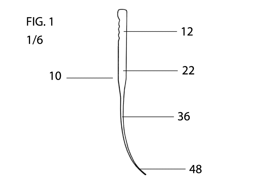
FIG. 1 is a side view of a first embodiment of a tool according to the present
invention.
FIG. 2 is a front view of the tool of figure 1.
FIG. 3 is a cross section side view of a conventional toilet showing the tool
of figure 1 in
position to rake waste from the mouth of the toilet trap way passage.
FIG. 4 is a cross section side view of a conventional toilet showing the tool
of figure 1 in
contact with the obstruction.
FIG. 5 is a cross section side view of a conventional toilet showing the tool
of figure 1 in
use, bending.
FIG. 6 is a cross section side view of a conventional toilet showing the tool
of figure 1 in
use, deforming to follow the curve of the toilet bowl trap way passage.
DETAILED DESCRIPTION
The invention will now be described in detail with reference to Figs. 1-5, in
which all numerals
refer to like portions of the inventive tool. FIGS. 1-2 illustrate an
embodiment of a toilet tool 10 of
this invention.
FIG. 1 is a side view of a toilet tool 10 of this invention. The tool 10 has
an elongate shaft 22
comprising a rigid handle portion 12, a flexible curved portion 36 and a
piercing tip portion 48.
The rigid handle portion 12 has a secure ergonomic grip, comprising a
plurality of ridges or
indentations, preferably provided on a side of the rigid handle portion 12
opposite the direction in
CA 02974786 2017-07-24
WO 2016/116913
PCT/1B2016/051620
9
which the flexible curved portion 36 curves away. The flexible curved portion
36 extends from the
distal end of the rigid handle portion 12, and tapers from the rigid handle
portion 12 to the piercing
tip portion 48. The rigid handle portion 12 is preferably straight and stiff
to provide effective
leverage on the flexible curved portion 36 and piercing tip 48, as well as to
transfer sufficient force
to the piercing tip portion 48 to dislodge an obstruction, or to rake away
debris. The flexible curved
portion 36 is resilient and biased to a curved configuration to provide
superior control of insertion
into the bend of the toilet trap way passage and to facilitate effective
raking of debris from the
blockage.
A person skilled in the art would appreciate that the terms "rigid" and
"stiff" imply values of material
properties, such as Young's modulus, which are sufficient to prevent
distortion of the portion of
the tool, as described, under typical loads exerted by a user when unblocking
a toilet.
Furthermore, the term "flexible" relates similarly to such properties, wherein
the properties take
values such that the tool will conform to the shape of the toilet bowl under
typical loads, whilst
deforming elastically but not plastically. The material must also be of
sufficient strength,
particularly under compression. It will be appreciated that where these terms
are used in this
specification they are not referring to absolute values but are relative to
other parts of the device.
For instance, the rigid handle portion 12 is relatively rigid compared with
the flexible curved portion
36, and the flexible curved portion 36 is relatively flexible compared with
the rigid handle portion
12. The exact measure of flexibility or rigidity is not critical to
performance of the invention. Suffice
it to say that a skilled person is capable of moulding a tool from a material
which would yield the
relative rigidity and flexibility properties, and select materials and
dimensions for the tool that
would create a device that could pierce or scrape a blockage, and bend around
a corner with
reasonable force.
The rigid handle portion 12 is of suitable length (described further below) to
provide the user with
sufficient reach to the bottom of the toilet bowl, including particularly deep
toilet bowl
configurations, without having to submerge a hand in unsanitary fluids.
The distal end of the rigid handle portion 12 tapers inwardly toward the
longitudinal axis at a
tapered section, the cross-sectional area of the distal end of the tapered
section matching the
cross-sectional area of the proximal end of the flexible curved portion 36
where the two meet.
This allows for a handle portion 12 which has sufficient girth to be
comfortable and practical to
hold, and a flexible curved portion 36 which is slender enough to flex around
the curved path of a
toilet trap way passage easily, and to pierce a blockage. The tapering of the
flexible curved portion
36, from the rigid handle portion 12 to the piercing tip portion 48, is
preferably gradual and
continuous, such that flexibility of the tool increases continuously towards
the piercing tip 48
CA 02974786 2017-07-24
WO 2016/116913
PCT/1B2016/051620
allowing the tool to conform to the shape of the toilet bowl trap way passage
and to direct the
applied downward force to an obstruction in this region. The tapering and
shape is provided to
ensure a suitable balance between strength and flexibility. The progressive
tapering toward the
piercing tip is also provided to avoid fatigue breakage due to stress
concentration associated with
5 abrupt interfaces. The continuous tapering towards the piercing tip
portion 48 may include the
flexible curved portion 36 alone, or include portions of the rigid handle
portion 12.
In the preferred embodiment of the invention the tool 10 is made from but not
limited to, any plastic
material from of a wide range of synthetic or semi-synthetic organic solids
and is preferably
10 moulded in one piece. Examples of suitable materials include silicone,
rubber, plastic (such as
PVC, PET, MDPE and PETG), nylon, a composite or any other similar types or
materials or blends
of materials. Additives can be added to such materials to inhibit bacteria
build up, such that after
bleaching or chlorination a protective barrier is formed to provide
antibacterial properties.
Preferably the elongate shaft 22 is integrally formed such that the rigid
handle portion 12 and
flexible curved portion 36 are provided together as a one-piece device.
Alternatively, the rigid
handle portion 12 and flexible curved portion 36 can be formed separately and
connected together
by a fixing means. Preferably the piercing tip portion 48 is also integrally
formed with the flexible
curved portion 36.
It is preferable that the tool 10 is made from a sanitisable material that is
easy to wipe clean. It is
preferable that the tool 10 is smooth in overall design and finish with no
crevices, corners, holes
or surface textures for dirt to collect in. This is ideally achieved by
forming the tool 10 from one
continuous piece of material. Advantageously, the tool 10 can also be provided
as part of a kit of
parts comprising the tool and a packet of cleaning wipes. The tool 10 is
preferably made by
injection moulding, but can also be milled from a block of material, or made
by 3D printing.
In the preferred embodiment the tool 10 has a length of 736mm, which has been
found to provide
optimal reach into the toilet bowl trap way passage without having to submerge
a hand in
unsanitary fluids. Furthermore, the rigid handle portion 12 has a length of
368mm to provide
sufficient length with which to grip the tool, and to provide optimal leverage
and transfer of force
to the flexible curved portion 36. Furthermore, the flexible curved portion 36
has a length of
368mm, which has been found to provide optimal flexibility for advancement
around the bend in
the toilet trap way passage, and the optimal of combination of flexibility and
resilience for raking
waste away from the blockage. In the preferred embodiment the rigid handle
portion 12 and
flexible curved portion 36 each account for 50% of the length of the tool 10,
which has been found
to provide an optimal balance between leverage and flexibility to conform to
the curvature of the
toilet bowl trap way passage. The tool is configured to be at least of a
length such that when the
CA 02974786 2017-07-24
WO 2016/116913
PCT/1B2016/051620
11
tip is in contact with the base of a standard toilet bowl, at least a portion
of the handle extends
beyond the rim of the toilet. This ensures that the user's hand does come into
contact with
unsanitary fluids. A person skilled in the art will appreciate that the
necessary dimensions and
proportions may vary according to typical toilet dimensions and proportions.
In the preferred
embodiment, the tapering of the depth of the flexible curved portion varies
from 10mm at the
proximal end, 7mm half way along its length, and 5mm at the blunt piercing
portion. In the
preferred embodiment, the tapering of the width of the flexible curved portion
varies from 19mm
at the proximal end, 17mm half way along its length, and 15mm at the blunt
piercing tip portion.
It should be noted that the depth is measured in the plane of the flexible
curved portion.
Specifically, this is the plane containing both the flexible curved portion
and the longitudinal axis
of the tool, as shown in figure 1 for example. The width is measured
orthogonal to this, in a plane
for which the longitudinal axis of the tool, at the position in question, is
perpendicular to the plane.
The piercing tip portion preferably comprises a substantially flat surface. In
the preferred
embodiment the piercing tip portion 48 points in a direction around 48 to the
longitudinal axis
defined by the rigid handle portion 12. This angle is measured such that the
angle between the
rigid handle portion and piercing tip portion direction is obtuse. Examples of
suitable combinations
of ranges dimensions of the various components, including the width and depth
of the rigid handle
portion, flexible curved portion and piercing tip portion, are summarised in
the tables below.
Elongate shaft length Rigid handle portion length Flexible curved
portion
(mm) (mm) length (mm)
300-720 150-360 150-360
720-750 350-380 350-380
800-1000 375-500 375-500
1000-1500 500-750 500-750
Rigid handle Rigid handle Flexible Flexible Piercing tip
Piercing
portion portion curved curved portion tip
portion
depth (mm) width (mm) portion depth portion width depth (mm) width
(mm)
(mm) (mm)
5-30 5-18 1-30 1-18 1-5 1-15
30-35 18-35 3-35 2-35 3-10 2-25
35-55 22-55 3-55 4-55 3-20 4-30
55-75 50-70 3-75 4-70 3-30 4-30
CA 02974786 2017-07-24
WO 2016/116913
PCT/1B2016/051620
12
It is preferred that the piercing tip portion 48 is shaped in such a way that
it can easily pierce
through a typical toilet blockage, but blunt in shape and finish so that the
tool 10 is completely
safe to use and does not pose any risk to the user or any other person. A
sharp piercing tip would
be unnecessary for the purpose of piercing through soft debris including
tissue paper and faecal
matter. Cross-sectional shapes of the piercing tip portion 48 include, but are
not limited to, square,
rectangular, circular or semi-circular, and may include rounded corners where
appropriate. It
should also be noted that the cross-sections referred to throughout, including
cross-sectional area
and cross-sectional shape, refer to a transverse cross-section in a plane
which intersects the
longitudinal axis of the tool at a right-angle.
FIG. 3 illustrates the present invention in position ready to be used to rake
waste away from the
mouth of the toilet bowl trap way passage 18 in a toilet 20. In the preferred
method of use the
user grasps the tool 10 by the rigid handle portion 12 and inserts the
flexible curved portion 36
and piercing tip 48 into the toilet bowl 14 to rake waste away from the mouth
of the toilet bowl trap
way passage 18. The flexibility of the flexible portion 36 relative to the
rigid handle portion
facilitates effective raking of debris in conformity with the contours of the
base of the toilet bowl
trap way passage. The piercing tip portion 48 is preferably blunt so as to
prevent damage to the
toilet.
FIG. 4 illustrates the present invention in position ready to be used to clear
an obstruction in a
toilet 20. In the preferred method of use the user grasps the tool 10 by the
rigid handle portion 12
and inserts the flexible curved portion 36 and piercing tip 48 into the toilet
bowl trap way passage
18 to make contact with the obstruction.
FIG. 5 illustrates the present invention under mild force. The user applies
mild force and pushes
the rigid handle portion 12 further down towards the toilet bowl 14 so a part
of the flexible curved
portion 36 of the tool 10 makes contact with the beginning of the trap way
passage 18.
FIG. 6 illustrates the present invention under moderate force and at maximum
reach. When the
user pushes down further towards the toilet bowl 14 the force is redirected
around the trap way
passage 18 bend, so that the piercing tip 48 can be easily pushed through any
part of the
obstruction. When the user pulls the piercing tip 48 back out of the toilet 20
the user can simply
flush the toilet 20 to clear the obstruction. However if the water line is
high because of the
obstruction, resulting from flushing the toilet prior to unblocking it, the
water will simply rush
through the hole made by the inventive tool 10, clearing the obstruction
without the need to flush
the toilet 20.
CA 02974786 2017-07-24
WO 2016/116913 PCT/1B2016/051620
13
It is to be understood that the present invention is not limited to the
details of the specific
embodiments described above, and is defined by reference to the accompanying
claims.