Note: Descriptions are shown in the official language in which they were submitted.
1
REDUNDANT VALVE SYSTEM
BACKGROUND OF THE DISCLOSURE
Field of the Disclosure
[0001] The disclosure generally relates to an apparatus and method
for
a redundant valve system used to regulate bleed air from turbine engines.
Specifically, the disclosure relates to a redundant valve system with two
pressure
regulating valves coupled and configured to reduce weight, reduce bulk, and
increase reliability.
Related Art
[0002] Pressure regulating valves have applications in a wide variety
of
areas that use pressurized fluids to drive pneumatic systems. These systems
typically require one or more pressure regulating valves controlled through
electronic
systems to permit operation remotely. One application for these pressure
regulating
valves are in aircraft systems that utilize a turbine engine.
[0003] Because these pressure regulating valves are used in critical
functions of the aircraft, such as the de-icing of engine cowls, it is
important to
introduce redundant valves in the event one of the valves fails. It would be
desirable
to place two pressure regulating valves in series in order to provide a
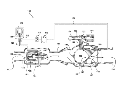
redundant
valve system for de-icing of the engine cowls and the like. However, due to
quick
changes in pressure of the bleed air and the short distance between the valves
in
some prior art systems, the pressure gradient across the valves often
fluctuates
quickly. This rapid change in pressure may cause undesirable oscillation in
operation of the valves and early failure of the valves. The industry solution
to this
Date Recue/Date Received 2022-07-29
2
problem has been to separate the valves using an extended duct of several feet
in
length (e.g., at least 4 feet in length). This increased distance between the
valves
allows the pressure gradient between the valves to be less susceptible to
fluctuations
in pressure. However, the introduction of an additional duct adds unnecessary
weight, bulk, and parts in a pressure regulating system that needs to be
compact and
light weight.
[0004] Accordingly, there is a need for a redundant pressure
regulating
valve system that is resistant to oscillation of the valves while also being
compact
and light weight.
SUMMARY OF THE DISCLOSURE
[0005] According to one aspect of the present disclosure, an object
is
to provide a redundant valve system to provide a regulated fluid flow,
comprising:
a housing having an inlet at an inlet end which receives a pressurized fluid,
and an outlet at an outlet end which provides the regulated fluid flow;
a first piston assembly arranged in the housing having a first cavity, the
first
piston assembly configured to regulate the fluid flow;
a first fluid connection connected to the first cavity and to a point along
the
housing at the outlet end;
a second piston assembly arranged in the housing downstream of the first
piston assembly having a second cavity, the second cavity having a second
fluid
connection to a vent, the second piston assembly configured to regulate the
fluid
flow when the first piston assembly fails;
an upstream valve to control the first fluid connection and control a position
of
the first piston assembly; and
a downstream valve to control the second fluid connection and control a
position of the second piston assembly;
Date Recue/Date Received 2022-07-29
2a
wherein the upstream valve is configured to close the first fluid connection;
and
wherein the downstream valve is configured to close the second fluid
connection.
[0005a] According to another aspect of the present disclosure, an
object
is to provide a redundant valve system to provide a regulated fluid flow,
comprising:
a housing having an inlet at an inlet end which receives a pressurized fluid
from a turbine engine, and an outlet at an outlet end which provides the
regulated
fluid flow of the pressurized fluid from the turbine engine;
a first piston assembly arranged in the housing having a first cavity, the
first
piston assembly configured to regulate the fluid flow;
a first fluid connection connected to the first cavity and to a point along
the
housing at the outlet end;
a second piston assembly arranged in the housing downstream of the first
piston assembly having a second cavity, the second cavity having a second
fluid
connection to a vent, the second piston assembly configured to regulate the
fluid
flow when the first piston assembly fails;
an upstream valve to control the first fluid connection and control a position
of
the first piston assembly; and
a downstream valve to control the second fluid connection and control a
position of the second piston assembly;
wherein the upstream valve is configured to close the first fluid connection;
and
wherein the downstream valve is configured to close the second fluid
connection.
[0005b] Other possible aspect(s), object(s), embodiment(s), variant(s)
Date Recue/Date Received 2022-07-29
2b
and/or advantage(s) of the present disclosure, all being preferred and/or
optional,
are briefly summarized hereinbelow.
[0006] For example, there has thus been outlined, rather broadly,
certain aspects of the disclosure in order that the detailed description
thereof herein
may be better understood and in order that the present contribution to the art
may be
better appreciated. There are, of course, additional aspects of the disclosure
that
will be described below and which will form the subject matter of the claims
appended hereto.
[0007] In one aspect, a redundant valve system to provide a regulated
fluid flow includes a housing having an inlet at an inlet end which receives a
pressurized fluid, and an outlet at an outlet end which provides the regulated
fluid
flow, a first piston assembly arranged in the housing having a first cavity,
the first
piston assembly configured to regulate the fluid flow, and a first fluid
connection
connected to the first cavity and to a point along the housing at the outlet
end. The
redundant
Date Recue/Date Received 2022-07-29
CA 02975264 2017-07-27
WO 2016/133800
PCT/US2016/017685
3
valve system may further include a second piston assembly arranged in the
housing
downstream of the first piston assembly having a second cavity, the second
cavity
having a second fluid connection to a vent, an upstream valve to control the
first fluid
connection and control a position of the first piston assembly, and a
downstream
valve to control the second fluid connection and control a position of the
second
piston assembly.
[0008] The redundant valve system may further include a regulator servo in
fluid connection with the first cavity, and a regulator bellow in fluid
connection with
the regulator servo and the point along the housing at the outlet end, wherein
the
regulator servo may be actuated to control the regulator bellow. The redundant
valve system may further include a relief valve in fluid connection with the
second
cavity. The vent may outlet to the atmosphere. The first piston assembly may
further include an orifice, wherein the orifice fluidly connects the inlet and
the first
cavity. The housing may further include a third cavity between the first
piston
assembly and the second piston assembly. The second piston assembly may
further include an orifice, wherein the orifice fluidly connects the second
cavity and
the third cavity. The upstream valve may be a solenoid operated valve. The
downstream valve may be a solenoid operated valve. The redundant valve system
may further include a controller configured to operate the downstream valve to
control the second fluid connection and control a position of the second
piston
assembly, and the controller may be further configured to determine when the
second piston assembly has failed open and subsequently control the upstream
valve to control the first fluid connection to operate the upstream valve to
control the
first fluid connection and control a position of the first piston assembly.
[0009] In another aspect, a redundant valve system to provide a regulated
fluid flow includes a housing having an inlet at an inlet end which receives a
CA 02975264 2017-07-27
WO 2016/133800
PCT/US2016/017685
4
pressurized fluid from a turbine engine, and an outlet at an outlet end which
provides
the regulated fluid flow of the pressurized fluid from the turbine engine, a
first piston
assembly arranged in the housing having a first cavity, the first piston
assembly
configured to regulate the fluid flow, a first fluid connection connected to
the first
cavity and to a point along the housing at the outlet end, a second piston
assembly
arranged in the housing downstream of the first piston assembly having a
second
cavity, the second cavity having a second fluid connection to a vent, the
second
piston assembly configured to regulate the fluid flow when the first piston
assembly
fails, an upstream valve to control the first fluid connection and control a
position of
the first piston assembly, and a downstream valve to control the second fluid
connection and control a position of the second piston assembly, wherein the
upstream valve is configured to close the first fluid connection, and wherein
the
downstream valve may is configured to close the second fluid connection.
[0010] The redundant valve system may further include a regulator servo in
fluid connection with the first cavity, and a regulator bellow in fluid
connection with
the regulator servo and the point along the housing at the outlet end, wherein
the
regulator servo may be actuated to control the regulator bellow. The redundant
valve system may further include a relief valve in fluid connection with the
second
cavity. The vent may outlet to the atmosphere. The first piston assembly may
further include an orifice, wherein the orifice fluidly connects the inlet and
the first
cavity. The housing may further include a third cavity between the first
piston
assembly and the second piston assembly. The second piston assembly may
further include an orifice, wherein the orifice fluidly connects the second
cavity and
the third cavity. The upstream valve may be a solenoid operated valve. The
downstream valve may be a solenoid operated valve. The redundant valve system
may further include a controller configured to operate the downstream valve to
CA 02975264 2017-07-27
WO 2016/133800
PCT/US2016/017685
control the second fluid connection and control a position of the second
piston
assembly, and the controller may be further configured to determine when the
second piston assembly has failed open and subsequently control the upstream
valve to control the first fluid connection to operate the upstream valve to
control the
first fluid connection and control a position of the first piston assembly.
[0011] In this respect, before explaining at least one aspect of the
disclosure
in detail, it is to be understood that the disclosure is not limited in its
application to
the details of construction and to the arrangements of the components set
forth in
the following description or illustrated in the drawings. The disclosure is
capable of
aspects in addition to those described and of being practiced and carried out
in
various ways. Also, it is to be understood that the phraseology and
terminology
employed herein, as well as the abstract, are for the purpose of description
and
should not be regarded as limiting.
[0012] As such, those skilled in the art will appreciate that the conception
upon which this disclosure is based may readily be utilized as a basis for the
designing of other structures, methods, and systems for carrying out the
several
purposes of the disclosure. It is important, therefore, that the claims be
regarded as
including such equivalent constructions insofar as they do not depart from the
spirit
and scope of the disclosure.
[0013] There has thus been outlined, rather broadly, certain aspects of the
disclosure in order that the detailed description thereof herein may be better
understood, and in order that the present contribution to the art may be
better
appreciated. There are, of course, additional aspects of the disclosure that
will be
described below and which will form the subject matter of the claims appended
hereto.
CA 02975264 2017-07-27
WO 2016/133800
PCT/US2016/017685
6
BRIEF DESCRIPTION OF THE DRAWINGS
[0014] FIG. 1 illustrates a turbine engine schematic with bleed air that is
siphoned from the turbine engine in accordance with an aspect of the
disclosure.
[0015] FIG. 2 illustrates the redundant valve system with the downstream
valve regulating and open in accordance with an aspect of the disclosure.
[0016] FIG. 3 illustrates the redundant valve system with the downstream
valve closed in accordance with an aspect of the disclosure.
[0017] FIG. 4 illustrates the redundant valve system with the upstream valve
open in accordance with an aspect of the disclosure.
[0018] FIG. 5 illustrates the redundant valve system with the upstream valve
closed in accordance with an aspect of the disclosure.
DETAILED DESCRIPTION
[0019] Pressure regulating valves have applications in a wide variety of areas
that use pressurized fluids to drive pneumatic systems. These systems
typically
require one or more pressure regulating valves controlled through electronic
systems
to permit operation remotely. One application for these pressure regulating
valves
are in aircraft systems that utilize turbine engines.
[0020] Due to the cold conditions during flight, aircraft often use bleed air
from
the turbine engines in order to perform de-icing of the exterior portions of
the aircraft
such as engine cowls, wings, and the like. This bleed air can also be used to
maintain cabin pressurization, de-ice windows, maintain temperature of the
cabin
and luggage compartments, assist in the function of ejector seats, provide air
for
blown flaps, provide air for windshield blow mechanisms, and the like. For
example,
the de-icing of the engine cowls typically requires pressure regulating valves
to
CA 02975264 2017-07-27
WO 2016/133800
PCT/US2016/017685
7
regulate the bleed air to compensate for variations in throttle settings,
icing
conditions and the like in order to allow the system to be controlled
automatically or
from the aircraft cockpit. These valves need to be reliable in performance,
low in
weight, and compact in size. It is also preferable that these valves are self-
powered
by using the pressure generated within the system itself for supplying the
energy to
actuate the valve.
[0021] Reference in this specification to "one aspect," "an aspect," "other
aspects," "one or more aspects," or the like means that a particular feature,
structure, or characteristic described in connection with the aspect is
included in at
least one aspect of the disclosure. The appearance of, for example, "in one
aspect"
in various places in the specification are not necessarily all referring to
the same
aspect, nor are separate or alternative aspects mutually exclusive of other
aspects.
Moreover, various features are described which may be exhibited by some
aspects
and not by others. Similarly, various requirements are described which may be
requirements for some aspects but not other aspects.
[0022] FIG. 1 illustrates a system 1 that may include a turbine engine 2 and
fluid connections where bleed air from the turbine engine 2 is siphoned off
and
utilized for other purposes. The turbine engine 2 may be a turbojet engine, a
turboprop engine, a turboshaft engine, a propfan engine, or another
airbreathing jet
engine known in the art. As air enters the turbine engine 2 at the fan 8, the
air
travels through a compressor 14 where the air becomes heated and pressurized
to,
for example, temperatures around 1250 F and pressures around 350 psi. A
portion
of the air that passes through the compressor 14 may be siphoned off at an
outlet 32
and/or an outlet 34.
[0023] The turbine engine 2 may be in fluid connection with a first check
valve
6 along a conduit 36. Subsequently, there may be a precooler 4 to cool a
portion of
CA 02975264 2017-07-27
WO 2016/133800
PCT/US2016/017685
8
the bleed air with air from the compressor 14 and/or air from the fan 8
provided by a
conduit 38. Subsequently, the bleed air enters the redundant valve system 100,
which regulates the flow of bleed air based on pressure and directs it for
other
purposes such as de-icing the engine cowl, the wings, or the like at outlet 16
and/or
outlet 18. The bleed air may also be provided through outlet 20. This bleed
air can
also be used to maintain cabin pressurization, de-ice windows, maintain
temperature
of the cabin and luggage compartments, assist in the function of ejector
seats, blow
rainwater off the windshield, blow the flaps, and the like.
[0024] Although the redundant valve system 100 is illustrated in FIG. 1 as
being downstream of a precooler 4. In some applications, the precooler 4 may
not
be necessary and the redundant valve system 100 may be directly connected to
the
turbine engine 2 to siphon air pressurized by the compressor 14.
[0025] The system 1 may further include an engine starter 42, a high-
pressure shutoff valve 26, a precooler exhaust 28, and a fan air valve 22. The
system 1 may further include a controller implemented as a control module 40.
[0026] The control module 40 may sense the temperature from a temperature
sensor 30, may sense pressure in numerous areas of the redundant valve system
100, may sense temperature in numerous areas of the redundant valve system
100,
may sense positions of components of the redundant valve system 100, may
control
the fan air valve 22, and may control the high-pressure shutoff valve 26. The
control
module 40 may further control the redundant valve system 100. The control
module
40 may be implemented with dedicated hardware as defined herein and control
system components and/or receive sensor inputs with control lines 44. The
control
module 40 may sense when a valve of the redundant valve system 100 has failed
and further control a second valve of the redundant valve system 100.
CA 02975264 2017-07-27
WO 2016/133800
PCT/US2016/017685
9
[0027] FIG. 2 illustrates the redundant valve system 100 with the downstream
valve 104 regulating and open in accordance with an aspect of the disclosure.
The
redundant valve system 100 may include a housing 132 having an inlet 110 and
an
outlet 126. The outlet 126 may subsequently connect to the outlet 16 and/or
the
outlet 18 shown in Figure 1. Towards the inlet 110 end of the housing 132,
there is a
first piston assembly 134. The first piston assembly 134 may move
longitudinally
along a center line of the housing 132. The first piston assembly 134 may have
a
first cavity 140, which is in fluid connection with the outlet 126. The first
cavity 140
may be connected fluidly with the outlet 126 through the connection 125, the
regulator servo 114, the regulator bellows 112, and the connection 124. The
first
piston assembly 134 may also include a control orifice 130, which provides
pneumatic connection between the inlet 110 and the first cavity 140 of the
first piston
assembly 134.
[0028] Along the connection 125, there may be an upstream valve 102. The
upstream valve 102 may be a solenoid operated valve or some other similar
valve
known in the art. The upstream valve 102 may be actuated such that the ball
116
rests in the ball cavity 144 and does not block the connection 125. The
upstream
valve 102 may also be actuated such that the ball 116 moves down through the
connection 125 and blocks the connection 125 to close the upstream valve 102
as
shown in Figure 5.
[0029] The redundant valve system 100 may also include a second piston
assembly 146 towards the outlet 126 end of the redundant valve system 100. The
second piston assembly 146 may move longitudinally along a center line of the
housing 132. The second piston assembly 146, which may receive the flow of
bleed
air through the inlet orifice 108. The second piston assembly 146 has a second
cavity 152 as well as an interior face 148 and an exterior face 150. The
second
CA 02975264 2017-07-27
WO 2016/133800
PCT/US2016/017685
cavity 152 is in fluid connection with two vents 118 and 122 through
connection 154.
The two vents 118 and 122 vent to atmospheric pressure conditions. Under
normal
operation, the relief valve 156 is closed and the vent 118 is blocked. When
situations where the pressure in the second cavity 152 becomes too great, the
relief
valve 156 may be actuated in order to change the regulation level while
venting
through the vent 118 and reduce the pressure in the redundant valve system
100.
The vent 122 may be controlled by the downstream valve 104.
[0030] The downstream valve 104 may be a solenoid operated valve or
another similar valve known in the art. When the downstream valve 104 is not
used
to regulate the bleed air through the redundant valve system 100, the ball 158
blocks
the connection from the second cavity 152 to the vent 122. When the downstream
valve 104 is in operation, the ball 158 may be actuated by the downstream
valve 104
to cause the ball 158 to extend with the downstream valve 104 and second
cavity
152 through connection 154 out to vent 122. (See FIG. 3).
[0031] Under normal operation, the downstream valve 104 may be used to
shut-off or otherwise control the flow of bleed air through the redundant
valve system
100. The redundant valve system 100 may receive unregulated bleed air at the
inlet
110 and provide a regulated flow of bleed air at the outlet 126. When the
downstream valve 104 is used to shut-off or otherwise control the flow of
bleed air,
the upstream valve 102 is actuated such that the ball 116 rests in the ball
cavity 144.
The bleed air received at the inlet typically may have a temperature of around
1250
F with a pressure of approximately 350 psi for example. As bleed air enters
from the
inlet 110, it flows through the control orifice 130. The pressure from the
bleed air
acts on the first face 136 and second face 138 of the first piston assembly
134.
[0032] When the upstream valve 102 actuated such that the ball 116 does not
block the connection 125, there is a fluid connection between the inlet 110
and the
CA 02975264 2017-07-27
WO 2016/133800
PCT/US2016/017685
11
outlet 126 through the connection 125 through the regulator servo 114, the
regulator
bellows 112, and the connection 124. Because the outlet 126 is at a lower
pressure
than the inlet 110, the pressure on the first face 136 may be greater than the
pressure forces on the second face 138 and inside the first cavity 140 of the
first
piston assembly 134. Due to this difference in pressure force, the first
piston
assembly 134 is actuated towards the outlet 126 of the redundant valve system
100,
creating a passageway 142. The bleed air will be able to flow from through
inlet 110
through the passageway 142 towards the second piston assembly 146.
[0033] When it is desired to have bleed air exit from the outlet 126, the
downstream valve 104 is actuated such that the ball 158 will block the vent
122,
which would otherwise outlet to atmospheric pressure conditions. The fluid
connection between the second cavity 152 through the connection 154 and to the
vent 122 will be closed. Bleed air from the inlet 110 will flow in through the
inlet
orifice 108 into the second cavity 152 of the second piston assembly 146. The
pressure on the interior face 148 will be greater than on the exterior face
150, and
will cause the second piston assembly 146 to be actuated towards the outlet
126.
This will create a passageway for bleed air at the entrance 162. This will
allow bleed
air to flow through the passageway 160 through the entrance 162 and out of the
outlet 126.
[0034] The fluid connection between the inlet 110 and the outlet 126 may also
act as a feedback mechanism to control the flow of bleed air through the
redundant
valve system 100. This may be desirable when the second piston assembly 146 is
locked open or if it fails to restrict the flow of air through passageway 160
below the
relief pressure set by the relief valve 156. When the flow of bleed air out of
the
redundant valve system 100 increases, the pressure at the outlet 126 will also
increase. The connections 124 and 125 create a feedback passage into the first
CA 02975264 2017-07-27
WO 2016/133800
PCT/US2016/017685
12
cavity 140. An increase in the pressure at the outlet 126 will increase the
pressure
inside the first cavity 140 and create a retarding force onto the second face
138 of
the first piston assembly 134. The first piston assembly 134 may be actuated
towards the inlet and restrict the flow of bleed air through the passageway
142.
[0035] The regulator servo 114 and regulator bellows 112 may also be used
to control the feedback pressure in the first cavity 140. The regulator servo
114 may
be an electrofluid servo valve, which receives an analog or digital input
signal to
actuate the regulator bellows 112 from the control module 40. The regulator
bellows
112 may be used to control the regulator servo 114 in adjusting the feedback
pressure through the connections 124 and 125 from the outlet 126. The
regulator
bellows 112 may be actuated to decrease or increase feedback pressure from the
outlet 126 depending on the desired flow of bleed air through the redundant
valve
system 100.
[0036] FIG. 3 illustrates the redundant valve system 100 when the
downstream valve 104 is actuated to shut-off or otherwise control the flow of
bleed
air in accordance with an aspect of the disclosure. When the downstream valve
104
is used to relieve the flow of bleed air and it is desired to stop the flow of
bleed air
through the outlet 126, the downstream valve 104 will be actuated such that
the ball
158 will be actuated towards the downstream valve 104, opening the fluid
connection
between the second cavity 152 to the vent 122. Because the vent 122 outlets to
atmospheric pressure, the pressure inside the second cavity 152 will be less
than the
pressure at the outlet 126. The pressure on the exterior face 150 of the
second
piston assembly 146 will be greater than the pressure on the interior face 148
of the
second piston assembly 146. The second piston assembly 146 will be actuated
towards the inlet 110 end of the redundant valve system 100. This will close
the
entrance 162 and restrict the flow of bleed air past the second piston
assembly 146.
CA 02975264 2017-07-27
WO 2016/133800
PCT/US2016/017685
13
[0037] In some previous designs, there was a fluid connection between the
first cavity 140 and a point along the housing 132 between the first piston
assembly
134 and the second piston assembly 146. In this situation, the pressure of the
feedback bleed air into the first cavity 140 would be relatively high. This
would cause
the first piston assembly 134 to close, which would stop the flow of bleed at
the inlet
110. In turn, this would drop the pressure at the fluid connection point and
cause the
first piston assembly 134 to open again. The process would repeat causing
oscillations in the opening/closing of the first piston assembly 134, which
unnecessary introduced extra wear and tear on the system. By establishing a
fluid
connection with the outlet 126 through the connections 124 and 125, the
pressure of
the outlet 126 remains significantly lower than the pressure at the inlet 110.
This
prevents the first piston assembly 134 from unnecessarily opening and closing
due
to the pressure within the first cavity 140.
[0038] FIG. 4 illustrates the redundant valve system 100 with the upstream
valve 102 actuated to allow the flow of bleed air in accordance with an aspect
of the
disclosure. In the event of failure of the second piston assembly 146, the
second
piston assembly 146 will fail open. The passageway 160 may permit the flow of
bleed air past the second piston assembly 146. Because of the fluid connection
between the first cavity 140 and the outlet 126, the pressure within first
cavity 140
will be lower compared to the pressure at the inlet 110. The pressure on the
first
face 136 will be greater than the pressure on the second face 138, which will
actuate
the first piston assembly 134 into an open position. This will permit the
bleed air to
flow through the passageway 142. The bleed air will continue past the second
piston
assembly 146 through the passageway 160 and out of the outlet 126.
[0039] FIG. 5 illustrates the redundant valve system 100 when the upstream
valve 102 is actuated to control the flow of bleed air in accordance with an
aspect of
CA 02975264 2017-07-27
WO 2016/133800
PCT/US2016/017685
14
the disclosure. When it is desired to restrict the flow of bleed air out of
the outlet
126, the upstream valve 102 may be actuated to cause the ball 116 to block the
connection 125. By blocking the connection 125, the fluid connection between
the
first cavity 140 and the outlet 126 may be closed. Now, when the bleed air
flows
from the inlet 110 through the control orifice 130 and into the first cavity
140, the
pressure inside the first cavity 140 will be roughly equivalent to the
pressure at the
inlet 110. The pressure on the first face 136 will be roughly equivalent to
the
pressure on the second face 138. Due to the larger surface area of the second
face
138, the first piston assembly 134 may be actuated towards the inlet and seal
the
passageway 142. By sealing the passageway 142, the flow of bleed air from the
inlet 110 through the redundant valve system 100 will be stopped.
[0040] Accordingly, a redundant pressure regulating valve system that is
resistant to oscillation of the valves while also being compact and light
weight has
been disclosed. The bleed air controlled by the redundant pressure regulating
valve
system may be used to de-ice cowls, maintain cabin pressurization, de-ice
windows,
maintain temperature of the cabin and luggage compartments, assist in the
function
of ejector seats, provide air for blown flaps, provide air for windshield blow
mechanisms, and the like. The disclosed valves are reliable in performance,
low in
weight, and compact in size. These valves may be self-powered by using the
pressure generated within the system itself for supplying the energy to
actuate the
valve.
[0041] Further in accordance with various aspects of the disclosure, the
methods described herein are intended for operation with dedicated hardware
implementations including, but not limited to, processors, microprocessors,
computers, PCs, semiconductors, application specific integrated circuits
(ASIC),
programmable logic arrays, cloud computing devices, and other hardware devices
CA 02975264 2017-07-27
WO 2016/133800
PCT/US2016/017685
constructed to implement the methods described herein.
[0042] The many features and advantages of the disclosure are apparent
from the detailed specification, and, thus, it is intended by the appended
claims to
cover all such features and advantages of the disclosure which fall within the
true
spirit and scope of the disclosure. Further, since numerous modifications and
variations will readily occur to those skilled in the art, it is not desired
to limit the
disclosure to the exact construction and operation illustrated and described,
and,
accordingly, all suitable modifications and equivalents may be resorted to
that fall
within the scope of the disclosure.