Note: Descriptions are shown in the official language in which they were submitted.
CA 02975827 2017-08-03
WO 2016/133503
PCT/US2015/016366
AIRCRAFT STARTING AND GENERATING SYSTEM
BACKGROUND OF THE INVENTION
[0001] The subject matter disclosed herein relates generally to a combination
of a
bidirectional energy conversion brushless electric rotating device that
converts
electrical energy to mechanical energy in start mode and mechanical energy to
electrical energy in generate mode. In particular, the subject matter relates
to an
aircraft starting and generating system, that includes a three electric
machine set, a
Starter/Generator (S/G), and an IGBT based and digitally controlled device,
referred
to herein as an Inverter/Converter/Controller (ICC).
[0002] There currently exist starter generator systems for aircraft, which are
used to
both start an aircraft engine, and to utilize the aircraft engine after it has
started in a
generate mode, to thereby provide electrical energy to power systems on the
aircraft.
High voltage direct current (DC) power can be derived from an aircraft turbine
engine
driven generator and converter (EGC). Alternating current (AC) power can be
derived from an AC generator driven by an aircraft turbine engine, or from
conversion
of DC power into AC power. It is known to use a wide band gap device to
achieve
efficiencies in a high voltage DC system of an aircraft turbine engine driven
generator
and converter (EGC) or in DC link voltage generation from an AC generator
driven
by an aircraft turbine engine. Likewise, it is known to use a wide band gap
device to
achieve efficiencies in an AC system of an aircraft turbine engine driven
generator
and converter (EGC) or in AC link voltage from a DC generator driven by an
aircraft
turbine engine. Low switching losses, low conduction losses, and high
temperature
capability are three advantages of a wide band gap device.
[0003] It is desirable to control a wide band gap device in a power generation
system
of an aircraft in order to consistently achieve the efficiencies.
BRIEF DESCRIPTION OF THE INVENTION
[0004] In one aspect, an aircraft starting and generating system, includes a
starter/generator that includes a main machine, an exciter, and a permanent
magnet
generator, an inverter/converter/controller (ICC) having a MOSFET-based bridge
configuration that is connected to the starter/generator and that generates AC
power to
drive the starter/generator in a start mode for starting a prime mover of the
aircraft,
1
CA 02975827 2017-08-03
WO 2016/133503
PCT/US2015/016366
and that converts AC power, obtained from the starter/generator after the
prime mover
have been started, to DC power in a generate mode of the starter/generator,
and a
main bridge gate driver configured to drive the MOSFET-based bridge. The main
bridge gate driver operates to drive the MOSFET-based bridge during start mode
using Space Vector Pulse Width Modulation (SVPWM) and during generate mode
using reverse conduction based inactive rectification.
[0005] In another aspect, a method of controlling an aircraft starting and
generating
system having a starter/generator that includes a main machine, an exciter,
and a
permanent magnet generator, an inverter/converter/controller (ICC) having a
MOSFET-based bridge configuration connected with the voltage output of the
main
machine winding, and main bridge gate driver configured to drive the MOSFET-
based bridge. The method includes, if in start mode, supplying power to the
MOSFET-based bridge and driving the main MOSFET-based bridge during start
mode using Space Vector Pulse Width Modulation (SVPWM), and wherein the
driving the main MOSFET-based bridge during start mode starts a prime mover of
the
aircraft, and if in generating mode, driving the MOSFET-based bridge using
reverse
conduction based inactive rectification to convert AC power, obtained from the
main
machine winding of the starter/generator, to DC power.
[0006] In another aspect, an aircraft includes an engine, and a
starter/generator
connected to the engine, and having a main machine, an exciter, and a
permanent
magnet generator. An inverter/converter/controller (ICC) having a MOSFET-based
bridge configuration is connected to the starter/generator and generates AC
power to
drive the starter/generator in a start mode for starting the engine, and
converts AC
power, obtained from the starter/generator after the engine has been started,
to DC
power in a generate mode of the starter/generator. A main bridge gate driver
is
configured to drive the MOSFET-based bridge during start mode using Space
Vector
Pulse Width Modulation (SVPWM) and during generate mode using reverse
conduction based inactive rectification.
BRIEF DESCRIPTION OF THE DRAWINGS
[0007] In the drawings:
2
CA 02975827 2017-08-03
WO 2016/133503
PCT/US2015/016366
[0008] FIG. 1 illustrates a prior art environment of an overall S/G and ICC
engine
starting and power generating system for the present subject matter.
[0009] FIG. 2 is a block diagram of the overall S/G and ICC engine starting
and
power generating system of FIG. 1.
[0010] FIG. 3 is a block diagram of the S/G and ICC engine starting and power
generating system of FIGS. 1 and 2 in start mode.
[0011] FIG. 4 is a block diagram of the S/G and ICC engine starting and power
generating system of FIGS. 1 and 2 in generate mode.
[0012] FIG. 5 is a section view of the S/G in FIG. 1.
[0013] FIG. 6 is block diagram of the S/G and ICC engine starting and power
generating system having a main machine MOSFET-based bridge.
[0014] FIG. 7 is an example circuit diagram of a reverse conduction based
inactive
rectification MOSFET-switching methodology.
[0015] FIG. 8 is a block diagram of the S/G and ICC engine starting and power
generating system, with a load leveling unit having a MOSFET-based bridge.
[0016] FIG. 9 is a block diagram of the S/G and ICC engine starting and power
generating system, with a four-leg MOSFET-based bridge.
DESCRIPTION OF EMBODIMENTS OF THE INVENTION
[0017] The subject matter disclosed herein is usable in a system such as that
shown in
FIGS. 1-5. In one embodiment, an S/G and ICC engine starting and power
generating
system 50 includes an S/G 100 and an ICC 200. As illustrated in FIG. 1, FIG. 2
and
FIG. 5, the S/G 100 is a combination of three electric machines, including a
main
machine 110, an exciter 120, and a PMG 130. This arrangement is called a three-
machine set. The main machine 110 can be a salient synchronous machine. A
stator
112 of the main machine 110 connects to a main IGBT/Diode Bridge 210 of the
ICC
200. A rotor 114 of the main machine 110 connects to an output of a full wave
or half
wave-rotating rectifier 116 located inside a shaft 118 of the main rotor 114.
An
exciter rotor 122 has a three-phase winding that connects to an input of the
rotating
rectifier 116, and an exciter stator 124 includes a DC winding and a three-
phase AC
winding that connects to an exciter IGBT/Diode bridge 212 of the ICC 200
through a
contactor 220 that is shown in FIG. 2. FIG. 2 provides a block diagram of the
S/G
3
CA 02975827 2017-08-03
WO 2016/133503
PCT/US2015/016366
and ICC system 50, with emphasis on the components making up the main
IGBT/Diode bridge 210 and the exciter IGBT/Diode bridge 212.
[0018] The ICC 200 shown in FIG. 2 includes two IGBT/Diode bridges: the main
bridge 210 and the exciter bridge 212. The main bridge 210 and the exciter
bridge
212 are also referred to as a main inverter/converter and an exciter
inverter/converter,
respectively. Each is controlled by a digital control assembly. The assembly
that
controls the main IGBT/Diode Bridge 210 is called the main digital control
assembly
230. Alternatively, it can also be called the starter inverter digital control
assembly in
start mode and the generator converter control assembly in generate mode. The
assembly that controls the exciter IGBT/Diode Bridge 212 is called the exciter
digital
control assembly 240. Alternatively, it can also be called the exciter
inverter digital
control assembly in start mode and the exciter converter digital control
assembly in
generate mode. The main digital control assembly 230, along with its embedded
software, controls the main bridge 210 that generates AC power to drive the
S/G in
start mode and converts the AC power to DC power requested on the aircraft in
generate mode.
[0019] The S/G and ICC engine starting and power generating system 50 has two
operating modes: start mode and generate mode. In start mode, the S/G and ICC
system 50 is powered from a separate power source, VDC 60, whereby the
connection
to the separate power source VDC 60 is shown in FIG. 1 and FIG. 2. The main
machine 110 works as a three-phase wound field salient synchronous motor in
start
mode. Two things have to happen in order to produce torque at the shaft of the
synchronous motor. The first is to input three-phase alternating currents to
the three-
phase winding of the main stator 112, and the second is to provide excitation
current
to the main rotor 114. The frequency of the currents to the main stator 112 is
provided so as to be proportional to the speed of the main machine. The three
phase
alternating currents are provided by the main IGBT/Diode Bridge 210. The
rotating
field generated by the three-phase current interacts with the magnetic field
generated
by the main rotor 114, thus creating the mechanical torque at the shaft of the
main
rotor 114.
[0020] Providing an excitation current to the main rotor 114 is a challenge in
conventional generating systems because of the following. At the beginning of
4
CA 02975827 2017-08-03
WO 2016/133503
PCT/US2015/016366
starting, any synchronous machine based exciter generates no power. At low
speed,
the synchronous machine based exciter cannot generate sufficient power to
power the
main rotor. This is because for any synchronous based exciter, its DC
excitation
winding does not transfer power to the rotor winding. In fact, for
conventional
generating systems, the power can only be transferred from mechanical energy
on the
shaft. Therefore, in order to start the engine, the power that generates the
main rotor
excitation current must come from the exciter stator 124. In other words, the
energy
for the excitation during start mode crosses the air gap of the exciter 120.
Obviously,
a rotating transformer is desired. Conversely, in generate mode, the main
machine
110 works as a three-phase wound field salient synchronous generator. To
produce
electricity, one thing happens, i.e., excitation current is provided to the
main rotor
114. A conventional synchronous exciter can be utilized for that purpose. The
different modes require different power sources for excitation. One mode needs
AC
three-phase currents in the exciter stator 124, and the other needs DC current
in the
exciter stator 124.
[0021] A dual functional exciter stator works in conjunction with the
contactor 220
located in the ICC. By switching the contactor to its appropriate position,
the winding
in the exciter stator is configured into an AC three phase winding during
start mode.
In this mode, the exciter stator 124 with the AC three phase winding and the
exciter
rotor 122 with another AC three phase form an induction exciter. Controlled by
the
exciter digital control assembly 240 in the ICC, the direction of the phase
sequence of
the AC three phase winding is opposite from the direction of the machine
shaft. Thus,
the induction exciter operates in its braking mode. In generate mode, the
winding in
the exciter stator 124 is configured into a DC winding. The exciter stator 124
with the
DC winding and the exciter rotor 122 with the AC three-phase winding form a
synchronous exciter. Without adding any size and/or weight to the exciter, the
configured AC and DC windings generate the necessary rotating field in the air
gap
between the exciter rotor 122 and exciter stator 124 during start mode and
generate
mode respectively. Additionally, the AC winding transfers the power from the
exciter
stator 124 to the exciter rotor 122 during start mode.
[0022] In both start mode and generate mode, whenever IGBTs 215 of the main
IGBT/Diode bridge 210 commutate, the mechanical position information of the
main
CA 02975827 2017-08-03
WO 2016/133503
PCT/US2015/016366
rotor 114 becomes needed for the power switch commutation. As shown in FIG. 2
and detailed in FIGS. 3 and 4, a sensorless rotor position signal 0, We (rotor
position,
rotor speed) is generated by the main digital control assembly 230. The rotor
position
signal is constructed through voltage and current signals of the S/G by the
embedded
software in the main digital control assembly 230
[0023] FIG. 3 presents a block diagram of the S/G and ICC system 50 in start
mode.
There are three electric machines¨the main synchronous motor 110, the
induction
exciter 120, and the PMG 130. The main synchronous motor 110 and the induction
exciter 120 play an important role in start mode. The main IGBT/Diode Bridge
210
receives DC input power from a DC bus (for example, 270 VDC), and inverts the
DC
power to AC power. The three-phase AC currents generated by the inverter feed
into
the main synchronous motor 110. The gating signals to generate the AC currents
are
controlled by the starter inverter digital control assembly 230. The starter
inverter
digital control assembly 230 measures Phase a current, Phase b current, and DC
bus
voltage. The Phase a and b currents are transferred to a and 13 currents in
the
synchronous stationary frame by using a Clarke transformation realized through
the
embedded software in the main digital control assembly 230. The a axis
coincides
with the a axis that is located at the center of the Phase a winding of the
main stator,
while the 13 axis is 90 electrical degrees ahead of a axis in space. The a and
13 currents
are further transferred to d and q currents in the synchronous rotational
frame by using
a Park transformation realized through the same embedded software. The d axis
is
aligned with the axis of the excitation winding of the main rotor 114, while
the q axis
is 90 electrical degrees ahead of the d axis in space.
[0024] As shown in FIG. 3, there are two current regulation loops¨d and q
loops.
The outputs of the d and q loops are d and q voltages that are transferred
back to a and
13 voltages by using an Inverse-Park transformation before fed into the Space
Vector
Pulse Width Modulation (SVPWM). In order to perform Park and Inverse-Park
transformations, the main rotor position angle is determined. The a and 13
voltages are
the inputs to the SVPWM which generates the gating signals for the IGBT
switches.
The switching frequency can be set at 14 kHz, or to some other appropriate
frequency.
[0025] As shown in FIG. 3, similar to the starter inverter digital control
assembly 230,
the exciter inverter digital control assembly 240 also has Clarke, Park, and
Inverse-
6
CA 02975827 2017-08-03
WO 2016/133503
PCT/US2015/016366
Park transformations. Also, the exciter inverter digital control assembly 240
has d
and q current regulation loops. The gating signals are generated by its
corresponding
SVPWM. Because, as mentioned previously, the fundamental frequency of the
exciter IGBT/Diode bridge 212, or the exciter inverter, is fixed at 1250 Hz or
at some
other appropriate frequency, and the exciter 120 has no saliency on its rotor
122 and
stator 124, the rotor position information can be artificially constructed by
using
formula lift, where f=1250 Hz and t is time. This is different from the main
inverter,
i.e., the real time rotor position information is not needed in this case. The
SVPWM
switching frequency of the exciter inverter is 10 Hz in one possible
implementation,
whereby other appropriately chosen switching frequencies can be utilized,
while
remaining within the spirit and scope of the invention.
[0026] In a second embodiment in start mode, the exciter 120 is configured as
an
induction machine operating in its braking mode, or alternatively described,
the
exciter 120 acts like a three-phase rotating transformer. The three-phase
winding of
the exciter stator 124 generates a rotating field that induces three-phase
voltages in the
exciter rotor 122. The direction of the rotating field is controlled opposite
from the
rotating direction of the main machine 110. Thus, the frequency of the voltage
in the
exciter rotor 122 increases along with the rotor speed during start mode. The
DC
power from an external power source is converted to three-phase 1250 Hz power
(or
to some other appropriate frequency) by the exciter IGBT/Diode Bridge 212. The
power crosses the air gap and is transferred to the winding of the exciter
rotor 122.
The three-phase voltages are then rectified by the rotating rectifiers 116
inside of the
rotor shaft of the main generator. The rectified voltage supplies the
excitation power
to the rotor 114 of the main machine 110. Once the rotor speed reaches the
engine
idle speed, start mode terminates and generate mode begins. The exciter rotor
122
receives energy from both the exciter stator 124 and the rotor shaft 118. At
zero
speed, all the energy comes from the exciter stator 124. The energy from the
shaft
118 increases along with the increase of the rotor speed.
[0027] A sensorless implementation for constructing the main rotor position
information by the digital control assembly 230 along with its embedded
software
includes two parts: a) high frequency injection sensorless estimation, and b)
voltage
mode sensorless estimation. The high frequency injection sensorless estimation
7
CA 02975827 2017-08-03
WO 2016/133503
PCT/US2015/016366
covers from 0 rpm to a predefined low speed, such as 80 rpm. The voltage mode
sensorless estimation covers from the speed, such as 80 rpm, to a high
rotational
speed, such as 14,400 rpm, where the engine is pulled to its cut-off speed.
Most other
sensorless methods, including the voltage mode sensorless mentioned above,
fail at
zero and low speed because these methods fundamentally depend on back-EMF. The
high frequency injection method does not depend upon the back-EMF. Therefore,
the
method is feasible to use for the speed from 0 to a predefined low speed, such
as 80
rpm. Accordingly, there is achieved rotor position estimation at rpm and at
low speed
of the main synchronous machine. The actual realization of the sensorless is
described below.
[0028] As shown in FIG. 3, while the speed of the main machine 110 is below 80
rpm
or the frequency of the main machine 110, fo<=8 Hz, a pair of 500 Hz sine
waveform
voltages V., Vi are superimposed on the inputs of the SVPWM. This 500 Hz
frequency is called the carrier frequency. Other appropriate carrier
frequencies can be
utilized while remaining within the spirit and scope of the invention. In FIG.
3, this
carrier frequency is represented by symbol We. The response of the current in
each
phase to these two superimposed voltages contains the rotor position
information.
[0029] Each phase current of the main stator has several components. As shown
in
FIG. 3, the Phase a and b currents are transferred to a and 13 axes through
Clarke
transformation. The a and 13 currents contain the fundamental component with
frequency of cor, the positive sequence component with frequency of ok, the
negative
sequence component with frequency of 2wr¨we. The positive sequence component,
We is useless because it does not contain any rotor position information.
Accordingly,
this component is removed completely. As illustrated in FIG. 3, the a and 13
currents
are rotated by ¨wet degrees. Thus, the positive sequence component becomes a
DC
signal, which is then eliminated by using a 2nd order high pass filter, or
some other
type of high pass filter (e.g., 1st order, or 3rd order or higher). The
remaining
components, the fundamental frequency component and negative sequence
component, contain the rotor information. However, the rotor position is
determined
before applying the fundamental current to the machine at zero speed and also,
at zero
and low speed the fundamental component is very weak. The only component that
can reliably extract the rotor position information is the negative sequence
8
CA 02975827 2017-08-03
WO 2016/133503
PCT/US2015/016366
component. After the previous rotation, the frequency of the component is
changed to
2cor-2ctie. Another rotation, 2ctiet, is then performed by the digital control
assembly
230. The output of the rotation goes through a 6th order low pass filter, or
to some
other appropriate low pass filter (e.g., 1st, 2nd, . . . or 5th order low pass
filter). Using
ipze to represent the remaining signal of the 13 current and icaii to
represent the
remaining signal of the a current, one obtains the following angle:
[0030] 0' = 0.5 tan'
\=ICC29i
[0031] Unfortunately, the frequency of the above angle has two times frequency
of
the fundamental frequency, and thus it cannot be directly used to the Park and
Inverse-Park transformations. To convert the above angle to the rotor position
angle,
it is detected whether 0' is under a north pole to south pole region or under
a south
pole to north pole region. If the 0' is under the north pole to south pole
region, the
angle is
[0032] 0=0',
[0033] and if the 0' is under the south pole to north pole region, the angle
is
[0034] 0=0' z.
[0035] This angle is then utilized in the Park and Inverse-Park
transformations in the
d and q current regulation loops. As shown in FIG. 3, a band-stop filter (500
Hz filter
as shown in FIG. 3, whereby other stop band frequencies can be utilized while
remaining within the spirit and scope of the invention) is placed between
Clarke and
Park transformations to eliminate the disturbances of the carrier frequency on
the d
and q current regulation loops.
[0036] This high frequency injection sensorless method works satisfactorily at
zero or
low speed. However, the method will not work as well with the speed with which
the
frequency is close to or higher than the carrier frequency. Accordingly,
another
sensorless method is utilized when the speed goes above a certain threshold
rotational
speed, such as 80 rpm. This method is the voltage mode sensorless method, as
described below.
[0037] The realization of the voltage mode sensorless is accomplished by the
following. Although the method has been used in an induction motor and a PM
motor, it has not been applied to a salient synchronous machine because the
stator
9
CA 02975827 2017-08-03
WO 2016/133503
PCT/US2015/016366
self-inductances are not constants, and instead, the inductances are functions
of the
rotor position. The conventional a and 13 flux linkage equations in the
synchronous
stationary frame, which are used to generate the rotor angle by arctangent of
the 13 flux
linkage over the a axis flux linkage, are not practical to be used for a
salient wound
field synchronous machine because the inductances change all the time. To
overcome
this problem, in the second embodiment, a pair of artificial flux linkages 2'
and 4' as
well as their expressions, are derived:
f Arc, =ferccdt=
M038] f(vcc¨ Rsicc) dt¨ Lq iccl
t Arp = f erp dt = f (Vp ¨ RO) d t ¨ Lqip 1
[0039] where Rs and Lq are the main stator resistance and q axis synchronous
inductance respectively. Both of the machine parameters are constant.
Fortunately,
2' and 4' align with the a and 13 flux linkages, respectively, and the angle
[0040] 0 = tan-l(Arp/Arc, )
[0041] is actually the rotor angle that can be used for Park and Inverse-Park
transformations once the machine speed is above the threshold rotational
speed, such
as above 80 rpm. The equations can be implemented in the embedded software of
the
digital control assembly 230. This approach provides for reliable rotor
position angle
estimation while the machine speed is above a certain rotational speed, e.g.,
above 80
rpm.
[0042] A combination of two separate methods, the high frequency inject
sensorless
method and the voltage mode sensorless method, can provide the rotor position
information with sufficient accuracy throughout the entire speed range of the
synchronous machine based starter.
[0043] During starting, the voltage applied by the main inverter on the main
machine
110 is proportional to the speed and matches the vector summation of the back-
EMF
and the voltage drops on the internal impedances of the main machine 110. The
maximum applicable voltage by the inverter is the DC bus voltage. Once the
vector
summation is equal to the DC bus voltage, the inverter voltage is saturated.
Once the
saturation occurs, the speed of the main machine 110 cannot go any higher, and
the d
and q current regulation loops will be out of control. Often, the inverter
will be over-
current and shut off The main digital control assembly 230 measures the line-
to-line
voltages, Vab and Vbe that are sent to the exciter digital control assembly
240. A
CA 02975827 2017-08-03
WO 2016/133503
PCT/US2015/016366
Clarke transformation is applied to these two line-to-line voltages. The
vector
summation of the two outputs of the transformation is used as the feedback of
an
auto-field weakening loop, as shown in FIG. 3. The DC bus voltage is factored
and
used as the reference for the control loop. The auto-field weakening control
loop
prevents the inverter voltage from the saturation, and, thus, prevents the
main inverter
current regulation loops from going out of control and shutting off
[0044] The auto-field weakening can be combined with a near unity power factor
control scheme to accomplish higher power density at high speed while the
inverter
voltage is saturated. By way of example and not by way of limitation, near
unity
corresponds to a power factor greater than or equal to 0.9 and less than 1Ø
While the
auto-field weakening maintenances the air gap field, there is applied a
predetermined
d-axis current profile that pushes the main machine 110 to operate in a near
unity
power factor region. As can be seen in the following equation, because the
auto-field
weakening, besides the term coLmd(iffid) remains consistently significant, and
term
coLmqidiq becomes significant too. This significantly increases the power
density of
the S/G:
[0045] P=coLmd(if +id)iq ¨coLmqidiq,
[0046] where P and co are electromechanical power and rotor speed
respectively, and
Lmd and Lmq are d and q magnetizing inductances, respectively.
[0047] The torque density at the speed below the base speed can be increased.
As
mentioned previously, there are two current regulation loops in the main
inverter
digital control assembly 230. One is the d axis loop and the other is the q
axis loop.
In general, the q loop controls the torque generation and the d loop controls
the field
in the air gap. This approach is also called a vector control approach. In
order to
achieve high torque density, the machine-to-magnetic saturation region is
driven into
by applying sufficient rotor excitation current if and the torque generation
current iq.
However, after the currents reach certain levels, no matter how the magnitudes
of the
currents iq, id, and if are increased, the torque remains the same because the
machine is
magnetically saturated. The remedy is to utilize the vector control set up to
maximize
the reluctance torque of the machine. The electromechanical torque generated
by the
machine is:
[0048] T=Lmd(if+ id)iq ¨ Lmqidiq,
11
CA 02975827 2017-08-03
WO 2016/133503
PCT/US2015/016366
[0049] where Lind and Lmq are d and q magnetizing inductances respectively.
Once
the machine is magnetically saturated, the term, Lmd(iffid) becomes a
constant.
Therefore, the way to generate a reluctance torque is to apply negative id to
the
machine. Knowing id=I sin 6 and Iq=I cos 6, performing an optimization to the
above
equation, one arrives an optimum profile of the id current:
l(
q) j((
-m -mq)2
[0050] id
2
[0051] where is the internal flux linkage of the machine.
[0052] An approximate 38% torque increase can achieve by applying the id
profile at
the input of the vector control, based on simulations performed by the
inventors. In
summary, with the vector control set and appropriate id current profile
obtained, the
torque density of the machine increases dramatically.
[0053] In a third embodiment configuration and control of the ICC to achieve
maximum efficiency of power generation is applicable to the generate mode of
the
S/G and ICC system 50.
[0054] In generate mode, as shown in FIG. 2, the main machine 110 becomes a
synchronous generator and exciter 120 becomes a synchronous generator. The PMG
130 provides power to the exciter converter through a rectifier bridge as
shown. The
exciter converter includes two active IGBT/Diode switches in exciter
IGBT/Diode
bridge 212, as illustrated in FIG. 4. The IGBT/Diode switches with solid lines
at their
gates are the ones used for the exciter converter. These are IGBT switch
number 1
and IGBT switch number 4. During generate mode, IGBT 1 is in PWM mode and
IGBT 4 is on all the time. The rest of the other IGBTs are off Number 2 diode
is
used for free wheeling. IGBT 1, IGBT 4 and Diode 2 plus the exciter stator
winding,
form a buck converter that steps down the DC bus voltage, for example, 270
VDC, to
the voltage generating the desired excitation current of the synchronous
exciter.
[0055] Inactive and active rectification is configurable. Controlled by the
exciter
converter digital control assembly 240 and the main converter digital control
assembly 230, the main IGBT/Diode Bridge can become an inactive rectifier or
an
active rectifier, depending upon the application. For an application where the
power
flow has only a single direction, the IGBT/Diode Bridge is configured into a
diode
12
CA 02975827 2017-08-03
WO 2016/133503
PCT/US2015/016366
operational bridge by the main converter digital control assembly 230. For an
application where the power flow has bi-directions, the IGBT/Diode Bridge is
configured into an IGBT and diode operational bridge by the same digital
control
assembly. When the power flow direction is from the ICC to the load, the S/G
and
ICC system is in generate mode. When the power flow direction is from the load
to
the ICC, the system is in so called regeneration mode, which is actually a
motoring
mode. In the inactive rectification, only the intrinsic diodes in the IGBT
switches of
the main inverter, also called main IGBT/Diode Bridge, are utilized. The
voltage
regulation is accomplished by the embedded software in the exciter digital
control
assembly 240, and the generator converter digital control assembly 230 keeps
the
IGBTs in the main inverter off, as illustrated in FIG. 4. There are three
control loops
controlling the voltage of POR. The most inner one is the current regulator.
The
measured excitation current is the feedback, and the output of the AC voltage
regulator is the reference. The current regulator controls the excitation
current at the
commanded level. The next loop is the AC voltage loop. As shown in FIG. 4, the
feedback signal is max llVabl,IVbel,IVeall. The reference is the output of the
DC
voltage regulator. The AC voltage loop plays an important role in keeping the
DC
voltage of the point-of-regulation (POR) in a desired range during load-off
transients.
The last control loop is the DC voltage loop. The measured voltage at the POR
is
compared with the reference voltage, 270 VDC. The error goes into the
compensation regulator in the corresponding digital controller. Thus, the DC
voltage
of the POR is regulated.
[0056] As mentioned previously, for the power generation application where
regeneration is required, the main IGBT/Diode Bridge will be configured into
an
active rectifier. In such a configuration, the voltage regulation is realized
through the
following. As illustrated in FIG. 4, both the embedded codes in the exciter
digital
control assembly and in the main digital control assembly are structured
differently
from those of the inactive rectification. Regarding the control on the exciter
side, the
excitation current loop becomes a PI control loop only. The reference of the
control
loop is generated through a look up table that is a function of the DC load
current.
The table is generated in such a way the current in the main stator approach
to its
minimum possible value. The control on the main side outer control loop is the
DC
13
CA 02975827 2017-08-03
WO 2016/133503
PCT/US2015/016366
voltage loop. The reference is 270 VDC; the feedback signal is the POR
voltage. As
shown in FIG. 4, the control loop is a PI controller with a feedforward of the
DC
output power added to the output of the PI controller. The DC output power is
equal
to the product of the DC output current and the POR voltage. The sum of the
feedforward signal and the output of the PI controller is a power command that
is
utilized as the reference for the inner control loop, which is also a PI
controller. The
feedback signal is the power computed by using the voltages and currents of
the
generator as shown in FIG. 4. The output of the inner control loop is the
voltage
angle Ov and is utilized to generate the SVPWM vectors Vd* and Vq*. The two
vectors are the input of the Park inverse transformation. The output of the
transformation is the input of the SVPWM as shown in FIG. 4.
[0057] Control of the IGBT converter can combine auto-field modification and
over-
modulation to achieve optimum efficiency of the IGBT generate mode operation.
[0058] As presented in FIG. 4, Vd* and Vq* are calculated through the
following
equations:
[0059] Vd*=1V*1 sin Ov
[0060] Vq*=1V*1 cos Ov
[0061] where IV*1=Vmag.
[0062] To optimize the efficiency, first, Vmag is chosen to be 1 pu, thus
forcing the
converter into the full over-modulation region and completely dropping the
IGBT
switching caused by SVPWM. This minimizes the IGBT switching losses. The
IGBT acts like phase shifting switching.
[0063] Because Vmag is constant, the power loop regulates the power by
adjusting
the angle Ov. When the load is zero, Ov approaches to zero, and when the load
increases, Ov increases.
[0064] The second factor of achieving the optimized efficiency is to optimize
the
exciter field current so id current is minimized. Thus, the conduction losses
of the
IGBTs and copper losses of the generator are minimized. It is found that the
exciter
field current is directly related to the DC load current. The higher DC load
current is,
the higher exciter field current is required. For the purpose of achieving of
minimum
exciter field current, a look up table is generated through measurement. The
input of
the look up table is the DC load current, and the output of look up table is
the
14
CA 02975827 2017-08-03
WO 2016/133503
PCT/US2015/016366
command of the exciter field current of the exciter stator. The table is
generated in
such a way that for each a DC load current point, an optimal exciter field
current is
found when id current is at its minimum. Such a control method not only
achieves the
optimal efficiency of the S/G and ICC system, but also provides an effective
approach
such that the operational point can easily swing from generate mode to
regenerate
mode, i.e., motoring mode. Thus, sending back the excessive energy on the DC
bus
to the generator in a fastest manner is accomplished. The third aspect of the
third
embodiment is directed to providing an IGBT commutation approach during
generate
mode. The IGBTs' commutation is based on a sensorless voltage mode, which is a
similar sensorless approach used in start mode. However, because the operating
mode
changes between diode only mode and IGBT mode, the rotor position angle is
determined before going into the IGBT mode. Vc, and Vp are obtained directly
from
the line-to-line voltage measurement instead of from the SVPWM commands.
[0065] Regeneration can be accomplished by absorbing excessive energy on the
DC
bus into the machine while regulating the bus voltage simultaneously. During
generate mode, there can be excessive energy created by the load. Such
excessive
energy raises the DC bus voltage. This energy can be absorbed by the machine
through the regeneration approach provided by the over-modulation SVPWM of
this
invention. During this situation, the main inverter digital control reverses
the
direction of the voltage angle 0v, and forces the main IGBT/Diode Bridge into
motoring mode. Thus, the direction of the power flow will be reversed. The
power
will flow from the load into the machine. The over-modulation keeps the IGBTs
from
switching, thus, minimizes the switching losses. This aspect of the invention
provides
a fast way to swing the main IGBT/Diode Bridge from generate mode to
regenerate
mode, and vice versa.
[0066] Other embodiments and configurations in the foregoing environment are
contemplated in the subject matter of the present disclosure. For example, a
fourth
embodiment is illustrated in FIG. 6. The fourth embodiment has elements
similar to
the first, second, and third embodiments; therefore, like parts will be
identified with
like numerals, with it being understood that the description of the like parts
of the
first, second, and third embodiments apply to the fourth embodiment, unless
otherwise noted.
CA 02975827 2017-08-03
WO 2016/133503
PCT/US2015/016366
[0067] One difference between the prior embodiments and the fourth embodiment
is
that the fourth embodiment has removed the contactor 220. While the contactor
220
is not included in the fourth embodiment, alternative embodiments of the
invention
can include a contactor 220, as described herein.
[0068] Another difference between the prior embodiments and the fourth
embodiment
is that the fourth embodiment, as shown, replaces the IGBT/Diode bridge of
each of
the exciter 120 and main machine 110 with a metal-oxide-semiconductor field-
effect
transistor (MOSFET)-based bridge configuration, shown as a main machine MOSFET
bridge 310 and an exciter MOSFET bridge 312. Each respective MOSFET bridge
310 includes an array of individually-controllable MOSFET devices 314, and in
addition to a MOSFET body diode, each device 314 can be optionally configured
to
include an external diode configured across the MOSFET body diode.
Alternatively,
embodiments of the invention can enable the elimination of an external diode
that is
used for wide band gap MOSFET devices 314 due to the devices 314 having
undesirable body diode electrical characteristics, such as higher power
losses. The
main machine MOSFET bridge 310 is communicatively coupled with, and
controllable by a main machine digital control assembly 330. Likewise, the
exciter
MOSFET bridge 312 is communicatively coupled with, and controllable by an
exciter
digital control assembly 340.
[0069] Each MOSFET 314 and/or each MOSFET bridge 310, 312 can include one or
more solid state switches and/or wide-band gap devices, such as a silicon
carbide
(SiC) and/or gallium nitride (GaN)-based high bandwidth power switch MOSFET.
SiC or GaN can be selected based on their solid state material construction,
their
ability to handle large power levels in smaller and lighter form factors, and
their high
speed switching ability to perform electrical operations very quickly. Other
wide-
band gap devices and/or solid state material devices can be included.
[0070] Each of the digital control assemblies 330, 340 are shown coupled with
each
MOSFET 314 gate of the respective MOSFET bridges 310, 312, and operates to
control and/or drive each respective bridge 310, 312 according to the various
modes
described herein. For example, the main machine digital control assembly 330,
along
with its embedded software, can control the main machine MOSFET bridge 310
that
(1) generates AC power to drive the S/G 100 in start mode for starting a prime
mover
16
CA 02975827 2017-08-03
WO 2016/133503
PCT/US2015/016366
of the aircraft, and (2) converts AC power, obtained from the
starter/generator 100
after the prime mover have been started, to DC power in a generate mode of the
starter/generator 100, as described above. During operation of the 4th
embodiment,
the main machine digital control assembly 330 can controllably operate the
main
machine bridge 310 to switch the control method from start mode to generate
mode
after the starting of the prime mover of the aircraft.
[0071] In one example, the main machine MOSFET bridge 310 and main machine
digital control assembly 330 can be configured to drive the bridge 310 during
start
mode using SVPWM, as described herein. As used herein, "driving" a MOSFET
bridge can include operating gate control and/or switching patterns according
to a
control methodology example, e.g., SVPWM. Additional switching patterns are
possible.
[0072] In another example, the main machine MOSFET bridge 310 and main
machine digital control assembly 330 can be configured to drive the bridge 310
during generate mode using a reverse conduction based inactive rectification
methodology. One example of reverse conduction based inactive rectification
has
been illustrated in a simplified electrical circuit shown in FIG. 7. In the
first circuit
400, a single phase of current is shown traversing a first MOSFET 402 having
an
active gate (e.g. the current is traversing the MOSFET channel as opposed to
the
body diode) by conducting current in reverse, that is, conducting current in
the
MOSFET channel in the direction from the source terminal to the drain
terminal. The
current further traverses through an electrical load 404, and returns through
a second
MOSFET 406 having an active gate, also conducting in reverse. The first
circuit 400
further illustrates a third MOSFET 408 having an inactive gate (e.g. not
conducting
via the MOSFET channel).
[0073] The second circuit 410 illustrates a first controllable switching event
wherein
each of the second MOSFET 406 and third MOSFET 408 are shown having inactive
gates, and the return current conducts through each respective MOSFET 406, 408
body diode. During the first controllable switching event of the second
circuit 410,
the current is shown commutating from the second MOSFET 406 to the third
MOSFET 408. The third circuit 420 illustrates a second controllable switching
event
wherein the third MOSFET 408 is shown having an active gate and conducting
17
CA 02975827 2017-08-03
WO 2016/133503
PCT/US2015/016366
current in reverse via the MOSFET channel. In the third circuit 420, neither
the
second nor third MOSFET 406, 408 is conducting current via a respective body
diode.
[0074] While FIG. 7 illustrates only a single phase, controllable switching
event, the
method of reverse conduction based inactive rectification can be utilized to
control the
MOSFET bridge (via MOSFET gate control and timing) to provide three phase AC
power rectification to DC power, and described herein.
[0075] In yet another example, the main machine digital control assembly 330,
along
with its embedded software, can control the main machine MOSFET bridge 310
such
that the bridge 310 generates AC power to drive the S/G 100 in motoring mode
for
motoring and/or moving a prime mover of the aircraft, in order to perform
testing
and/or diagnostics on the S/G 100 and/or prime mover. In this example, the
main
machine MOSFET bridge 310 and main machine digital control assembly 330 can be
configured to operate and/or drive the bridge 310 during motoring mode using
SVPWM, as described herein.
[0076] Thus, the main machine MOSFET bridge 310 can controllably act to invert
and/or convert power, as controlled by the main machine digital control
assembly
330. While only the operation of the main machine MOSFET bridge 310 has been
described, other embodiments can include similar operations of the exciter
MOSFET
bridge 312, wherein the exciter MOSFET bridge 312 is controllably operated by
the
exciter digital control assembly 340 to drive the exciter MOSFET bridge 312
using
SVPWM during generate mode. As with the previous embodiments, while bi-
directional power flow is described (i.e. a starter/generator 100),
embodiments can
include single-directional power flow, such as a generator. Furthermore,
additional
components can be included, for example, a main machine MOSFET bridge 310
digital signal processor (DSP) to provide input relating to the timing and/or
method
operation of the main machine digital control assembly 330, such as by sensing
or
predicting the starter/generator 100 rotor position.
[0077] The embodiment can be further configured such that the main machine
MOSFET bridge 310 absorbs the excess electrical energy of the aircraft
electrical
power system by, for instance, operating the main machine digital control
assembly
330 to control the main machine MOSFET bridge 310 such that excess energy is
stored in the kinetic energy of the rotor and/or prime mover of the aircraft,
and
18
CA 02975827 2017-08-03
WO 2016/133503
PCT/US2015/016366
wherein the main machine bridge gate driver operates to drive the main machine
MOSFET-based bridge during regeneration mode using Space Vector Pulse Width
Modulation.
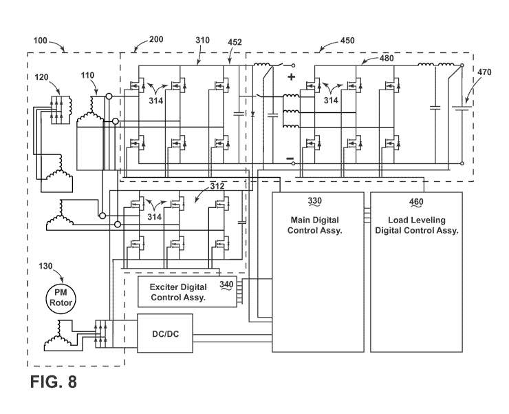
[0078] In a fifth embodiment, as shown in FIG. 8, the starter/generator 100
can
further include a load leveling unit (LLU) 450 selectively coupled with the DC
power
output 452 of the main machine 110 and/or ICC 200. The LLU 450 can include an
integrated redundant regeneration power conversion system, for example, having
a
power storage device 470 such as a battery, a fuel cell, or an
ultracapactitor. The
LLU 450 can be configured to operate such that electric energy of the aircraft
electrical power system is selectively absorbed and/or received by the power
storage
device 470 (i.e. "receive mode") during periods of excess power, for example,
when
excess energy is returned from aircraft electric flight control actuation or
excess
power generation from the starter/generator 100. The LLU 450 can be further
configured to operate such that electric energy of the power storage device
470 is
supplied (i.e. "supply mode") during periods of peak power, or insufficient
power
generation, such as during engine starting and/or high power system demands
such as
flight control actuation.
[0079] As shown, the LLU 450 can include an inverter/converter/controller,
such as
an LLU MOSFET-based bridge 480, similar to the main machine MOSFET bridge
310 described herein, and whose output is selectively paralleled with the DC
output of
the starter/generator 100. An LLU digital control assembly 460 can be included
and
configured to selectively drive the LLU MOSFET bridge 480 during various
operation modes. For example, when the LLU 450 is operating to supply DC power
to the DC power output of the starter/generator 100 during supply mode, the
LLU
digital control assembly 460 can be operating the LLU MOSFET bridge 480 gates
by
utilizing a bi-polar pulse width modulation (PWM) method. The LLU 450 can
operate in supply mode to provide power to the main machine MOSFET bridge 310
to
operate in start and/or motoring mode, as described herein. In another
example, when
the LLU 450 is operating to receive DC power from the DC power output of the
starter/generator during receive mode, the LLU digital control assembly 460
can be
operating the LLU MOSFET bridge 480 gates by utilizing a bi-polar PWM method.
19
CA 02975827 2017-08-03
WO 2016/133503
PCT/US2015/016366
[0080] The LLU 450 can operate in receive mode to absorb power from the main
machine MOSFET bridge 310 while operating in generate mode, as described
herein.
In this sense, the LLU 450 can operate to discharge power to the aircraft
electrical
system, as well as recharge from excess power on the aircraft electrical
system. The
embodiment can be further configured such that the main machine MOSFET bridge
310 absorbs the excess electrical energy of the aircraft electrical power
system in the
event of LLU 450 failure by, for instance, operating the main machine digital
control
assembly 330 to control the main machine MOSFET bridge 310 such that excess
energy is stored in the kinetic energy of the rotor and/or prime mover of the
aircraft,
and wherein the main machine bridge gate driver operates to drive the main
machine
MOSFET-based bridge during regeneration mode using Space Vector Pulse Width
Modulation. As with the embodiments of the invention described above, each
respective MOSFET bridge 310, 312, 480 includes an array of individually-
controllable MOSFET devices 314, and in addition to a MOSFET body diode, each
device 314 can be optionally configured to include an external diode
configured
across the MOSFET body diode.
[0081] In yet another example embodiment, as shown in FIG. 9, the
starter/generator
100 can further include a four leg inverter 550 coupled with the DC power
output 452
of the main machine 110 and/or ICC 200. The four leg inverter 550 can operate
to
convert DC power received from the DC power output 452 of the main machine 110
and/or ICC 200 to AC power in a generate mode, and can further operate to
generate
and provide DC power to drive the starter/generator in a start mode for
starting a
prime mover of the aircraft.
[0082] As shown, the four leg inverter/converter 550 can include an
inverter/converter/controller, such as a four leg MOSFET-based bridge 580,
similar to
the main machine MOSFET bridge 310 described herein, and configured having
three
outputs 582 for three distinct phases of AC power, and a fourth output 584 for
a
neutral output, relative to the three phases of AC power. In one example, the
three
phase AC output can be at 400 Hz. The embodiments can further include a four
leg
digital control assembly 560 configured to selectively drive the four leg
MOSFET
bridge 580 during various operation modes. For example, when the four leg
inverter/converter 550 is operating to convert DC power from the DC power
output
CA 02975827 2017-08-03
WO 2016/133503
PCT/US2015/016366
452 to three phase (and neutral) AC power during generate mode, the four leg
digital
control assembly 560 can be operating the four leg MOSFET bridge 580 gates by
utilizing a bi-polar PWM method. The four leg inverter/converter 550 can
further
operate in start mode to provide power to the main machine MOSFET bridge 310
to
operate in start and/or motoring mode, as described herein, by operating the
four leg
MOSFET bridge 580 gates utilizing a bi-polar PWM method.
[0083] The embodiment can be further configured such that the main machine
MOSFET bridge 310 absorbs the excess electrical energy of the aircraft
electrical
power system by, for instance, operating the main machine digital control
assembly
330 to control the main machine MOSFET bridge 310 such that excess energy is
stored in the kinetic energy of the rotor and/or prime mover of the aircraft,
and
wherein the main machine bridge gate driver operates to drive the main machine
MOSFET-based bridge during regeneration mode using Space Vector Pulse Width
Modulation. As with the embodiments of the invention described above, each
respective MOSFET bridge 310, 312, 580 includes an array of individually-
controllable MOSFET devices 314, and in addition to a MOSFET body diode, each
device 314 can be optionally configured to include an external diode
configured
across the MOSFET body diode.
[0084] Additional embodiments of the invention contemplate alternative
iterations of
the MOSFET-based bridges described herein. For example, one embodiment of the
invention can have an exciter MOSFET bridge 312 and a LLU MOSFET bridge 480.
Another embodiment of the invention can have a main machine MOSFET bridge 310
and a four leg MOSFET bridge 580. Yet another embodiment of the invention can
have only a main machine MOSFET bridge 310. Furthermore, any of the MOSFET
bridges described herein can operate under alternative or varying control
methods,
and can include similar or dissimilar materials and/or solid state devices.
Additionally, the design and placement of the various components can be
rearranged
such that a number of different in-line configurations could be realized.
[0085] The embodiments disclosed herein provide an aircraft starting and
generating
system having MOSFET-based bridge construction. One advantage that can be
realized in the above embodiments is that the above described embodiments
implement MOSFET-based controllable bridges that can perform both inverting
and
21
CA 02975827 2017-08-03
WO 2016/133503
PCT/US2015/016366
converting functions based on the control method and/or pattern. For example,
by
utilizing SVPWM for certain functions, the starter/generator can achieve
synchronous
gating while minimizing the losses in the MOSFET-based bridge. Furthermore,
when
conducting current across the MOSFET devices in the reverse direction of the
reverse
conduction based inactive rectification, the power losses across the MOSFET
can be
lower than the power losses caused by the forward voltage drop in a diode,
thus
further minimizing power losses.
[0086] Additionally, with the rise of electronic flight control actuation, the
demand on
electrical power systems for aircrafts has increased, compared to conventional
flight
control actuation. Moreover, when the increased demand on the electrical power
systems due to electronic flight control actuation has ceased, the increase in
available
power of the power systems can threaten other sensitive electronics that can
be
damaged by power surges. The LLU, incorporating the MOSFET-based gate control
methods described herein provide both supplemental electrical power when the
electrical demand is high, and absorb excess electrical power when the
electrical
demand is low.
[0087] Yet another advantage that can be realized in the above embodiments is
that
the wide-band game MOSFET devices have advantages of lower losses, higher
switching frequency, and higher operating temperature compared to the
conventional
semiconductor devices. Furthermore, while body diodes are utilized during the
control methods and tend to have higher power losses than MOSFET operation
alone,
the use of such diodes are minimized, which in turn provides lower power
losses for
the electrical system.
[0088] Yet another advantage that can be realized in the above embodiments is
that
the embodiments have superior weight and size advantages over the
starter/generator,
exciter, LLU, and four leg inverter/converter systems. Moreover solid state
devices
such as the MOSFET-based bridges have lower failure rates, and increased
reliability.
When designing aircraft components, important factors to address are size,
weight,
and reliability. The resulting embodiments of the invention have a lower
weight,
smaller sized, increased performance, and increased reliability system.
Reduced
weight and size correlate to competitive advantages during flight.
22
CA 02975827 2017-08-03
WO 2016/133503
PCT/US2015/016366
[0089] To the extent not already described, the different features and
structures of the
various embodiments can be used in combination with each other as desired.
That
one feature cannot be illustrated in all of the embodiments is not meant to be
construed that it cannot be, but is done for brevity of description. Thus, the
various
features of the different embodiments can be mixed and matched as desired to
form
new embodiments, whether or not the new embodiments are expressly described.
All
combinations or permutations of features described herein are covered by this
disclosure.
[0090] This written description uses examples to disclose the invention,
including the
best mode, and also to enable any person skilled in the art to practice the
invention,
including making and using any devices or systems and performing any
incorporated
methods. The patentable scope of the invention is defined by the claims, and
can
include other examples that occur to those skilled in the art. Such other
examples are
intended to be within the scope of the claims if they have structural elements
that do
not differ from the literal language of the claims, or if they include
equivalent
structural elements with insubstantial differences from the literal languages
of the
claims.
23