Note: Descriptions are shown in the official language in which they were submitted.
CA 02975857 2017-08-02
WO 2016/127004 PCT/US2016/016659
PERSONAL VAPORIZER WITH MEDIUM AND CHAMBER CONTROL
CROSS-REFERENCE TO RELATED APPLICATION
[0001] This application claims priority to U.S. Provisional Application No.
62/111,914,
filed February 4,2015, the entirety of which is hereby incorporated by
reference.
BACKGROUND
[0002] The present disclosure relates to the field of personal vaporizers
[0003] Personal vaporizers are handheld devices that vaporize a vaporizing
medium such
as a liquid solution or a wax. The vapor is then inhaled by its user. A
typical personal vaporizer
has an atomizer with a heating element that selectively heats the medium in
order to produce the
vapor. A rechargeable battery is also typically employed for powering the
atomizer.
[0004] Vaporizing media typically includes one or more of various essential
oils, such as
cannabis oil. Extracted flavorings can also be included.
[0005] Personal vaporizers for vaporizing wax media typically include a bowl-
or cup-
shaped structure at the atomizer into which wax media can be placed. Such
personal vaporizers
typically include a detachable mouthpiece that can be removed to provide
access to the atomizer
cup so that a user can place wax in the cup.
[0006] In use, the heating element of the atomizer is actuated to heat a
portion of the wax
sufficiently so that the wax is atomized. A user typically simultaneously
draws a breath through
the mouthpiece, pulling air into a vaporizing chamber defined between the bowl
and mouthpiece.
The air and atomized wax form a vapor that is drawn through the mouthpiece and
into the user's
lungs.
[0007] The effectiveness of medium vaporization diminishes as the temperature
within a
vaporization chamber drops, and the configuration of such a vaporization
chamber may affect the
quality of medium vaporization. Also, it can be desired to achieve complete or
near-complete
vaporization of media, thus minimizing unvaporized media, as well as to
preventing or impeding
unvaporized media from flowing or leaking out of the device.
SUMMARY
[0008] There is a need in the art for a personal vaporizer in which a user can
control a size,
shape, and/or configuration of a vaporization chamber. There is a further need
in the art for a
personal vaporizer having structure that minimizes the amount of media that is
not vaporized
1
CA 02975857 2017-08-02
WO 2016/127004 PCT/US2016/016659
during use, and a still further need in the art for a personal vaporizer that
resists leaking of
unvaporized media.
[0009] In accordance with one embodiment, the present specification provides a
personal
vaporizer, comprising an atomizer module comprising a bowl having a sidewall
and a proximal
edge, a heating element being arranged in or adjacent the bowl, the bowl being
configured to accept
a wax having an essential oil. The atomizer module is connectable to a battery
assembly so that
actuation of the battery delivers electrical energy to the heating element,
causing the heating
element to heat and vaporize a wax that may be in the bowl. An adapter module
is detachably
connected to the atomizer module, the adapter module having an elongated
hollow body and an
adapter plug. The adapter plug has a distal end, and the adapter plug is
arranged within the adapter
module elongated hollow body so that the distal end is disposed at or adjacent
the heating element
so that a vaporizing chamber is defined between the heating element and the
distal end of the
adapter plug.
[0010] In some such embodiments a portion of the distal end of the adapter
plug engages
the proximal edge of the bowl. Some such embodiments additionally comprise one
or more slots
formed through a side wall of the bowl.
[0011] In further embodiments, the plug is selectively movable longitudinally
relative to
the adapter module from a first longitudinal position to a second longitudinal
position.
[0012] In still further embodiments a vapor space is disposed between the
adapter plug and
an inner surface of the adapter module elongated hollow body.
[0013] In yet additional embodiments a distal surface of the plug defines a
distal cavity.
[0014] In yet further embodiments the distal end of the adapter plug is
arranged distal of
the proximal edge of the bowl. In some such embodiments a diameter of the
distal end of the
adapter plug is less than the diameter of the side wall of the bowl.
[0015] In accordance with another embodiment the present specification
provides a
method of using a personal vaporizer. The method includes detaching an adapter
module from an
atomizer module so as to gain access to a bowl of the atomizer module, the
bowl having a sidewall
and a proximal edge, a heating element being arranged in the bowl, and
depositing a wax having
an essential oil into the bowl. The adapter module is reattached to the
atomizer module so that an
adapter plug of the atomizer module is positioned at or adjacent the heating
element. The method
additionally comprises actuating the heating element so that the heating
element vaporizes at least
2
CA 02975857 2017-08-02
WO 2016/127004 PCT/US2016/016659
a portion of the wax, and drawing a breath through a mouthpiece so that
ambient air is mixed with
vaporized wax and drawn through and out of the mouthpiece.
[0016] Some such embodiments additionally comprise adjusting a longitudinal
position of
the adapter plug relative to an adapter body of the adapter module. In further
embodiments, when
the adapter module is reattached to the atomizer module a distal end of the
adapter plug is
positioned longitudinally distal of a proximal end of the bowl. In other
embodiments, when the
adapter module is reattached to the atomizer module a distal end of the
adapter plug engages a
proximal end of the bowl.
BRIEF DESCRIPTION OF THE DRAWINGS
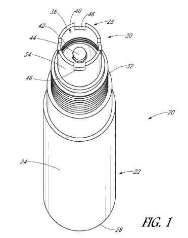
[0017] Figure I is a perspective view of a battery assembly for use in some
embodiments;
[0018] Figure 2 is a side view of the battery assembly of Figure 1;
[0019] Figure 3 is a side view of an embodiment of a personal vaporizer having
a modular
construction;
[0020] Figure 4 is an exploded view of the personal vaporizer of Figure 3;
[0021] Figure 5 is a cross sectional view taken along lines 5-5 of Figure 4;
[0022] Figure 6 shows the structure of Figure 5 in use vaporizing a medium;
[0023] Figure 7 is a perspective view of a personal vaporizer configured in
accordance
with another embodiment;
[0024] Figure 8 is an exploded view of the personal vaporizer of Figure 7
[0025] Figure 9A is an exploded view of an adapter module in accordance with
one
embodiment;
[0026] Figure 9B shows the adapter module of Figure 9A assembled in a first
position;
[0027] Figure 9C shows the adapter module of Figure 9A assembled in a second
position;
[0028] Figure 10A is another exploded view of the adapter module of Figure 9A;
[0029] Figure 10B shows the adapter module of Figure 10A assembled in the
second
position also depicted in Figure 9C;
[0030] Figure 11 is a cross-sectional view taken along lines 11-11 of Figure
7;
[0031] Figure 12 is a cross-sectional view of a portion of a personal
vaporizer having an
adapter module configured in accordance with another embodiment;
[0032] Figure 13 is a cross-sectional view of a portion of a personal
vaporizer having an
adapter module configured in accordance with still another embodiment; and
3
CA 02975857 2017-08-02
WO 2016/127004 PCT/US2016/016659
[0033] Figure 14 is a cross-sectional view of a portion of another embodiment
of a personal
vaporizer having an adapter module configured in accordance with yet another
embodiment.
DESCRIPTION
[0034] With initial reference to Figures 1 and 2, an embodiment of a battery
assembly 20,
or battery pack, for a personal vaporizer is illustrated. Certain features of
the illustrated battery
assembly 20 are typical of battery assemblies currently available on the
market. For example, the
battery assembly 20 may include a rechargeable battery, such as a lithium-ion
battery, enclosed
within a battery casing 22. The battery casing 22 may include an elongated
body 24 that extends
from a base or distal end 26 to a top or proximal end 28. An electronic
controller may also be
included within the casing 22 to control voltage, current, timing and the
like. A button 29 may be
provided for selectively actuating electricity delivery from the battery 20 to
the atomizer. In some
embodiments, the button 29 can include a light that indicates when power is
being delivered.
[0035] With continued reference to Figures 1 and 2, at and adjacent the
proximal end 28
of the battery assembly 20, the battery casing 22 defines a mount boss 30. The
mount boss 30
includes connecting structures for connecting vaporizing structures, such as
atomizers and fluid
chambers, to the battery. The elongated body 24 is disposed distally of the
mount boss 30. In some
embodiments, the body 24 may include a decorative coating or sleeve that is
configured to enhance
the look of the vaporizer. For example, the body 24 may come in many different
colors and/or
have one or more unique and aesthetically pleasing surface treatments. Some
embodiments may
include a decorative sleeve that is selectively removable.
[0036] In the illustrated embodiment, the battery assembly mount boss 30
comprises an
externally threaded portion 32 adjacent the decorative body 24. Preferably,
the externally threaded
portion 32 has a diameter somewhat smaller than a diameter of the decorative
body 24. An
extension 34 extends in a proximal direction from the externally threaded
portion 32, preferably
terminating in a top or proximal surface 36. As best shown in Figure 2, the
extension 34 preferably
is tubular, defining a mount cavity 40 therewithin and having internal threads
42. Preferably, a
diameter of the tubular extension 34 is less than the diameter of the
externally threaded portion 32.
A battery contact 44 is disposed within the tubular extension 34 at the base
of the mount cavity 40.
As shown, preferably a plurality of air intake slots 46 are formed in the
extension at and adjacent
the top surface.
4
CA 02975857 2017-08-02
WO 2016/127004 PCT/US2016/016659
[0037] As noted above, one or more vaporizing structures are attachable to the
battery
mount boss 30. Such vaporizing structures t body ypically include an atomizer,
mouthpiece and,
in some embodiments, a fluid chamber or one or more other vaporizer
structures, which can be
provided as separate pieces or combined as a single structure. The vaporizing
structures can be of
various styles, sizes, and configurations.
[0038] Vaporizing structures can also be attached to the battery assembly 20
in various
ways. In some embodiments, an atomizer can threadingly engage the external
threads 32 of the
battery mount boss 30. In other embodiments, an atomizer may threadingly
engage the internal
threads 42 of the mount cavity extension 40. Preferably, a pin or other
elongated contact extends
into the mount cavity 40 to engage the battery contact 44 so as to communicate
power from the
battery 20 to the atomizer. Additional embodiments can employ non-threaded
connection
structures such as detents, friction fits, J-locks, and the like.
[0039] With reference next to Figures 3-5, one embodiment of a personal
vaporizer 48
comprises an atomizer module 50 and a mouthpiece module 60 that are
threadingly attachable to
one another and to a battery 20. The illustrated atomizer module 50 has an
elongated body 52
having a distal end 56 and a proximal end 58. The distal end 56 is threadingly
attachable to the
mount boss 30 of the battery 20 so that electric power can be provided to a
heating element in the
atomizer. The mouthpiece module 60 also comprises a distal end 62 and a
proximal end 64. The
distal end 62 of the mouthpiece module 60 is threadingly attachable to and
detachable from the
proximal end 54 of the atomizer module 50. The mouthpiece module 60 preferably
is tubular,
delivering vapor V generated in the atomizer module 50 to and through an
outlet 65 at its proximal
end 64 for delivery to the user. As best shown in Figures 5 and 6, the
mouthpiece preferably is
tubular, defining a mouthpiece chamber 66 and a mouthpiece vapor passage 68
therewithin.
[0040] As best shown in Figure 5, the atomizer module 50 comprises a container
or bowl
70 at or adjacent the proximal end 54 of the atomizer module 50. The atomizer
bowl 70 preferably
defines bottom 72 and side walls 74 and is open at the top, or proximal, end
76. Preferably, the
bowl 70 is an insulator, and can be made of an insulator material such as a
ceramic. The heating
element is disposed within the bowl 70 and, in the illustrated embodiment,
comprises a coil 80
supported upon a transverse bar or wick 82 (coil support). The wire coil 80
can be constructed of
a durable, electrically-conductive material such as a metal (such as titanium,
kanthal, or nichrome)
that provides durability and electrical conduction to selectively power the
atomizer. With
CA 02975857 2017-08-02
WO 2016/127004 PCT/US2016/016659
additional reference to Figure 6, a vaporizing medium such as a wax W can be
placed into the
bowl 70 on or around the coil 80. This style of atomizer module can be
referred to as a skillet-style
atomizer module due to its bowl structure, which accommodates the wax and/or
other atomizable
media.
[0041] In the illustrated embodiment, a user gains access to the atomizer bowl
70 by
detaching the mouthpiece module 60. The user may then deliver vaporizing
media, such as the
wax W, through the open proximal end of the atomizer module 50 and into the
bowl 70. The user
preferably replaces the mouthpiece module 60 in order to use the personal
vaporizer 48.
[0042] The distal end 52 of the atomizer body has a plurality of slots 86
formed therein. A
distal atomizer connector pin (not shown) preferably is externally threaded so
as to threadingly
engage the internal extension threads 42 of the battery assembly. The pin
extends into the mount
cavity to engage the battery contact 44 so as to communicate electrical power
from the battery to
the coil when the button 29 is depressed. Also, the atomizer slots 86 and
battery boss slots 46
cooperate to enable ambient air A to be drawn through the distal end 52 of the
atomizer module
50. Preferably, an air aperture 88 is formed through the bowl 70 so that the
air A can flow through
the bowl 70 and past the coil 80.
[0043] In practice, and with particular reference to Figures 5 and 6, when the
user presses
the button 29 to actuate the battery 20, the coil eight is quickly heated,
causing a portion of the
wax W to be atomized. The user typically simultaneously draws a breath through
the mouthpiece
60, pulling air A into a vaporizing chamber 90 defined between the bowl 70 and
the surface of the
mouthpiece chamber 66, where it mixes with the atomized wax to form a vapor V.
The vapor V
is then pulled through the mouthpiece vapor passage 68 and into the user's
lungs.
[0044] Continuing with reference to Figures 5 and 6, the chamber 66 defined in
the
mouthpiece and above the bowl 70 is relatively large. Thus, a relatively large
vaporizing chamber
90 is defined between the mouthpiece chamber surface and the coil. Fast heat
dissipation is
especially prominent in vaporizer designs having large vaporizing chambers
such as that shown in
Figures 3-6. The effectiveness of medium vaporization diminishes as the
temperature drops within
the vapor chamber. As such, less usable vapor can be expected to be generated
from wax medium
vaporized in a large vaporizing chamber than from wax medium vaporized in a
small vaporizing
chamber. Also, in personal vaporizers, heat can dissipate relatively quickly
once the battery stops
energizing the coil. Although vapor is still generated after the coil is no
longer actuated, such
6
CA 02975857 2017-08-02
WO 2016/127004 PCT/US2016/016659
vapor generation will decrease quicker in a large vaporizing chamber than in a
small vaporizing
chamber.
[0045] Also, when the coil 80 is energized, and when the user draws vapor
through the
mouthpiece, the wax medium W can be expected to boil, resulting in
splattering, in which
unvaporized portions 92 of the medium splatter upon non-heated surfaces, such
as the surface of
the mouthpiece chamber 66. Further, when warmed but not vaporized, the
viscosity of the wax
medium can be lowered substantially, possibly causing it to be readily
flowable. In such a
condition, if the user tilts the vaporizer 48 on its side, or upside down, the
wax medium is
susceptible to flowing and may flow out of the bowl onto surfaces of the
mouthpiece chamber, or
even out of the mouthpiece outlet and/or through the bowl air aperture. During
such events, when
atomizable medium exits the bowl, the medium may be wasted by leaking or by
becoming adhered
to surfaces (such as portions of the mouthpiece chamber surface) where it will
not be heated
sufficiently to be atomized.
[0046] With reference next to Figure 7, an embodiment of a personal vaporizer
95
comprises a battery assembly 20 upon which an atomizer module 50 is mounted.
An adapter
module 100 is attached to the atomizer module and attaches to a mouthpiece
module 96 by way of
a tubular member 98.
[0047] With additional reference to Figure 8, the atomizer module 50
preferably comprises
an elongated body 52 having a distal end 54 and a proximal end 56. A bowl 70
has a bottom 72
and side walls 74 and is open at or adjacent its top, or proximal end 76. A
heating element is
arranged in the bowl, and preferably comprises at least one coil 80 wrapped
about a wick 82. The
bowl 70 is fit into the body 52 at and adjacent the proximal end 56 of the
atomizer body 52. The
distal end 54 of the atomizer body 52 includes air slots 86 and is configured
to attach to a mount
boss 30 of the battery assembly 20 so that the battery can selectively supply
electric power to the
coil 80.
[0048] With additional reference to Figures 9 and 10, the illustrated adapter
module 100
comprises an elongated, tubular adapter body 102 having a distal end 104 and a
proximal end 106
and defining an adapter body lumen 110 therewithin. The illustrated adapter
body 102 has internal
threads 112 adjacent its distal end 104 so as to be releasably attachable to
the threaded proximal
end 56 of the atomizer body 52. The proximal end 106 of the adapter body 102
also has internal
threads 114. A reduced-diameter portion 118 of the adapter body is defined at
and adjacent the
7
CA 02975857 2017-08-02
WO 2016/127004 PCT/US2016/016659
proximal end 106. Flow holes 120 are formed through a side wall of the adapter
body 102 in the
reduced diameter portion 118. In the illustrated embodiment, a pair of 0-ring
seats 122 are formed
distal of the flow holes 120. 0-rings 124 can be fit into and supported by the
0-ring seats 12.
[0049] With continued reference to Figures 7-10, the adapter module 100 also
includes an
adapter plug 130 having a distal end 132 and a proximal end 134. A head 136 is
defined at and
adjacent the proximal end 134, and the plug 130 has external threads 138
distal of the head 136. A
stop surface 139 is defined between the head 136 and the external threads 138,
which have a
diameter less than that of the head and 136. Preferably, the external threads
138 are sized and
adapted to engage with the internal threads 114 adjacent the proximal end 106
of the adapter body
102. An elongated shaft 140 extends between the head 136 and a distal base
portion 142 at and
adjacent the distal end 132. The distal base portion 142 has a distal outer
edge 144 at the distal end
132 which, in the illustrated embodiment, has a greater diameter than does the
shaft 140.
[0050] With specific reference to Figures 9B, 9C and 10B, the adapter plug 130
is
configured to be advanced into the adapter body lumen 110 so that the plug
threads 138 engage
the proximal threads 114 of the body 102. As such, the adapter plug 130 can be
held within the
adapter body 102 over a range of positions. For example, Figure 9B shows the
plug 130 in a first
position relative to the body 102 and Figures 9C and 10B show the plug 130
advanced distally
relative to the body 102 to a second position. In the second position, the
stop surface 139 of the
head and 36 is engaged with the proximal end 106 of the adapter body 102 so as
to prevent the
plug 130 from extending any further distally relative to the adapter body 102.
[0051] With additional reference again to Figures 7 and 8, and also to Figure
11, the tubular
member 98 fits over the reduced-diameter portion 118 of the adapter body 102
and engages 0-
rings 124 disposed in the seats 122 so as to create a seal.
[0052] The mouthpiece module 96 comprises a distal end 152 and a proximal end
154. 0-
ring seats 156 adjacent the distal end 152 have 0-rings 158 fit therewithin,
and the distal end 152
fits within the tubular member 98 so that the 0-rings 158 sealingly engage the
inner surface of the
tubular member 98. An outlet 160 is defined at the proximal end 154 of the
mouthpiece module
96.
[0053] In a preferred embodiment, the tubular member 98 is made of a clear
material such
as glass. It is to be understood, however, that other materials, such as a
metal, also can be used for
the tubular member. Further, additional embodiments may use different
structure to secure the
8
CA 02975857 2017-08-02
WO 2016/127004 PCT/US2016/016659
tubular member between the mouthpiece module and the adapter module. For
example, rather than
0-rings, the tubular member can be attached to one, the other, or both the
mouthpiece module and
adapter module by way of threads or other attachment structure. In still
further embodiments, the
tubular member can be integrally incorporated as part of the mouthpiece
module, but releasably
attachable to the adapter module.
[0054] With continued reference to Figures 7-11, the illustrated atomizer
module 50
preferably comprises a check valve 164 distal of the bowl 70. Preferably, a
distal pin of the
atomizer body 52 is configured to attach to the battery mount boss 30. Thus,
when the atomizer
module 50 is attached to the battery assembly 20, air can flow through the
atomizer air slots 86,
battery slots 46, and check valve 164 and into the atomizer module 50.
Structure of the check valve
and the connection of the atomizer module to the battery can vary as desired.
Some embodiments
may incorporate structure as discussed in Applicant's co-pending application
number 14/985,389,
filed December 30, 2015, the entirety of which is hereby incorporated by
reference. Further
embodiments may or may not include a check valve.
[0055] A vaporizing chamber 170 is defined between the distal end 132 of the
plug 130
and the coil 80. In the illustrated embodiment, when the adapter plug 130 is
fully advanced to the
second position as shown in Figures 9C, 9B and 11, the distal end 132 of the
plug 130 is disposed
within the bowl 70 and adjacent the coils 80.
[0056] Continuing with reference to Figure 11, a user may load the vaporizer
95 by
removing the adapter module 100 from the atomizer body 52 and placing a wax W
within the bowl
70, preferably atop the coil 80. The adapter body 102 is then replaced onto
the atomizer body 52.
When the user draws a breath through the mouthpiece 96 and presses the button
29 to energize the
coils. Ambient air A is drawn past the coil 80 and wax W is atomized and mixed
with the air A in
the vaporizing chamber 170 to form a vapor V. To exit the vaporizing chamber
170, the vapor V
travels laterally around the distal base portion 142 of the plug 130, and then
changes direction to
flow generally longitudinally between the distal base portion 142 and the side
wall 74 of the bowl
70. The vapor further flows through the adapter body lumen 110 between the
inner surface of the
adapter body 102 and the plug shaft 140, and further through the flow holes
120 and into a
secondary vapor chamber 172 formed by the tubular member 98. The vapor V then
flows into a
mouthpiece chamber 174 formed within the mouthpiece module 96, and further
through a
mouthpiece vapor passage 176 and out of the outlet 160.
9
CA 02975857 2017-08-02
WO 2016/127004 PCT/US2016/016659
[0057] In the illustrated embodiment, the distal end 132 of the plug 130 is
arranged very
close to the coil 80. As such, for example, splatter 92 that may occur when
the wax is boiled by
the coil 80 is contained by the distal end 132 of the plug 130 and thus
remains close to the coil 80.
In the illustrated embodiment, the distal end 132 of the plug is close enough
to the coil 80 so that
splatter 92 on the distal end 132 will be heated sufficiently to be atomized.
Further, with the distal
end 132 of the plug 130 close to the coil 80, the vaporizing chamber 170 is
quite small, and will
thus retain heat, resulting in a more thorough vaporization of vaporizing
media. In another
embodiment, the distal end of the plug is sufficiently close so that splatter
on the distal end is
warmed sufficiently that its viscosity reduces and it flows, or drips, back to
the coil, where it is
then vaporized. Thus, the illustrated embodiment and related embodiments
reduce or prevent
losses of vaporized atomized medium through splattering and/or flowing out of
the bowl.
[0058] In the illustrated embodiment, the user may adjust the size and
configuration of the
vaporizing chamber 170 as desired. For example, with specific reference to
Figures 9B and 11, the
user may remove the tubular member 98 so as to access the head 136 of the
adapter plug 130.
Rotating the adapter plug head 136 counterclockwise will move the adapter plug
130 proximally,
such as toward or to the first position illustrated in Figure 9B. In this
position, the distance between
the distal end 132 of the adapter plug 130 and the coil 80 is greater than it
is when the plug 130 is
in the second position, resulting in decreased atomization of media and faster
cooling of the
vaporizing chamber. For some users, and for some media, such configurations
may be preferred.
[0059] With specific reference again to Figure 11, an adjustment space 180 is
disposed
between the head 136 of the adapter plug 130 and the distal end 152 of the
mouthpiece module 96.
Preferably the space 180 is of the length sufficient to accommodate the plug
head 136 over the
plug's full range of longitudinal positions, such as between the first
position depicted in Figure 9B
and the second position depicted in Figures 9C and 11.
[0060] It is to be understood that, in some embodiments, the adapter body 102
is attached
to the atomizer 50 before the adapter plug 130 is inserted into the adapter
body 102. In other
embodiments, the adapter plug can be placed into the body before the body is
attached to the
atomizer module. Further, in some embodiments, in order to load the device
with vaporizing
media, a user may first remove the plug and then drop media such as wax
through the proximal
end of the adapter body and/or apply a portion of wax to the distal end of the
plug base. The plug
CA 02975857 2017-08-02
WO 2016/127004 PCT/US2016/016659
can then be advanced through the lumen of the body and into place with its
distal base adjacent
the coil.
[0061] It is to be understood that the inventive concepts discussed herein can
be applied to
a plurality of different structural embodiments. For example, with reference
next to Figure 12, a
cross-section of another embodiment of an adapter plug 190 and adapter body
102 is shown. In
the illustrated embodiment, the distal base 191 of the adapter plug 190 has a
diameter greater than
the inner diameter of the bowl 70. As such, the distal edge 192 of the adapter
plug 190 engages
the bowl upper edge 76. In this embodiment, preferably a plurality of slots
200 are formed in the
bowl side wall 74 at and adjacent the bowl upper edge 76. Thus, vapor V can
flow through the
slots 200.
[0062] Due to manufacturing variances, the position of the bowl upper edge 76
relative to
the proximal edge 56 of the atomizer module body 52 may vary somewhat from
vaporizer to
vaporizer. Since the plug 190 is threadingly advanceable within (or with) the
adapter body 102,
such variances can be accommodated so that the plug distal edge 192 engages
the bowl upper edge
76. In the embodiments discussed above, the adapter plug is advanced relative
to the adapter body.
In some embodiments, the plug may be held within the body, and advancement of
the distal end
of the plug is determined by the extent to which the adapter body is
threadingly advanced over the
atomizer module.
[0063] Continuing with reference to Figure 12, the distal base 191 of the
illustrated plug
190 has a distal cavity 194 defined by sloping surfaces 196. More
particularly, the sloping surfaces
196 are sloped relative to a longitudinal axis of the bowl 70. With the plug
190 appropriately in
place as shown, the plug distal cavity 194 is disposed immediately above the
bowl 70 and coil 80
of the atomizer module 50, and the vaporization chamber 170 is defined between
the bowl 70 and
plug distal cavity surfaces 196. Also, in the illustrated embodiment, the
shaft 198 of the plug 190
has a diameter substantially the same as the distal edge 192 of the plug base
191. As can be
appreciated, the vaporization chamber 170 is relatively small in this
configuration. Thus, heated
air and vapor within the vaporization chamber is more likely to retain that
heat for a longer time,
leading to better and more effective vaporization of the medium. Further, as
discussed above, if
desired, a user can adjust the size of the vaporization chamber by varying how
far the plug is
threaded into the adapter module.
11
CA 02975857 2017-08-02
WO 2016/127004 PCT/US2016/016659
[0064] Continuing with reference to Figure 12, the plug distal cavity 194
constrains vapor
V generated by heating the medium by the coil 80 in the bowl 70 within the
vaporizing chamber
170. Also, splatter and the like, which can be expected when heating the
medium, is contained
within the relatively small vaporization chamber. Further, with the plug
distal end 192 engaged
with the bowl upper edge 76, heated medium having low viscosity will be fully
or mostly retained
within the vaporization chamber 170 even if the vaporizer is tilted on its
side, upside down or the
like. Also, in the illustrated embodiment, the distal ends of the sloped
surfaces 196 of the plug
distal cavity 194 overhang portions of the bowl upper edge 76 so that splatter
and the like that may
accumulate on a sloping surface 196 of the plug distal cavity 194, when heated
to have a low
viscosity, can flow downwardly and drop back into the bowl 70 for possible
vaporization.
[0065] Continuing with reference to Figure 12, when the plug distal edge 191
is engaged
with the bowl upper edge 76, the only route for vapor V to escape the
vaporization chamber 170
is through the slots 200 in the bowl side walls 74. As such, vapor V must flow
through the slots
200 and into the lumen 110 defined between the plug shaft 198 and the adapter
body inner surface.
Vapor will continue to flow through the lumen 110 and out the flow holes 120
of the adapter body
102, as shown. It is to be understood that such a configuration forces the
vapor flow path to make
a plurality of substantial changes in flow direction, defining a tortuous
vapor pathway. As such,
media solids that may be entrained in the vapor are more likely to fall out of
the vapor and not be
carried out of the vaporization chamber with the vapor. Such entrained media
solids will thus be
retained within the vaporization chamber, possibly eventually being vaporized.
Thus, vapor quality
is improved and loss of unvaporized media is reduced. It is to be understood
that other
embodiments, including the embodiment discussed above in connection with
Figures 7-11, can
also employ tortuous vapor pathways.
[0066] With reference next to Figure 13, another embodiment of an adapter plug
210 is
shown. In this embodiment, the adapter plug 210 has a larger diameter at and
adjacent its distal
base 211 than it has at the shaft 218 proximal of the distal base 211. As
such, the lumen 110
between the plug shaft 218 and the inner surface of the adapter body 102 has a
greater cross-
sectional area adjacent the plug shaft 218 than it does adjacent the plug
distal base 211. This
configuration reduces constrictions on vapor flow. Further, in the illustrated
embodiment, the plug
210 has a proximal cavity 220 and plug apertures 222 that communicate the
lumen 110 with the
plug proximal cavity 220 so that vapor V can flow through the lumen 110 and
into the plug
12
CA 02975857 2017-08-02
WO 2016/127004 PCT/US2016/016659
proximal cavity 220, in addition to vapor flowing from the lumen 110 through
the flow holes 120
of the adapter body 102.
[0067] In yet additional embodiments, the adapter body may not have flow
holes. Thus,
vapor is constrained to flow from the lumen only into the plug proximal
cavity. The illustrated
adapter plug distal base also has a distal cavity 214 having a surface 216
defining a generally
semicircular cross-sectional shape. As such, the shape of the vaporization
chamber 170 is
somewhat different than, for example, in the embodiment of Figure 12. It is to
be understood that
various shapes for the plug distal cavity 214 can be employed as desired.
Still further embodiments
can include yet additional structural configurations. For example, rather than
(or in addition to)
having slots formed through the bowl side walls, slots can be formed through
the distal edge of the
plug base.
[0068] With reference next to Figure 14, a portion of another embodiment of a
personal
vaporizer 228 employing another embodiment of an adapter module 230 is shown.
In the illustrated
embodiment, the adapter module 230 comprises an elongated adapter body 232
having a tubular
outer wall 234 that defines proximal and distal cavities 236, 238 that are
separated by a septum
240. The septum 240 has a threaded mount aperture 242. An adapter plug 250 has
a threaded mount
portion 252 that fits into the mount aperture 242 formed in the septum 240 so
as to connect the
adapter plug 250 to the adapter body 232. Notably, in the illustrated
embodiment, the adapter plug
250 is inserted into the adapter body 232 via the distal cavity 238 of the
adapter body. The threaded
connection between the plug mount portion 252 and the body mount aperture 242
enables the plug
252 to be positioned over a range of longitudinal positions relative to the
adapter body 232.
[0069] The illustrated plug 250 has a distal cavity 254 defined at its distal
base 256. When
the plug 250 is installed on the atomizer body 232 as shown, a distal edge 258
of the plug 250 can
engage the upper edge 76 of the bowl 70 so that the vaporization chamber 170
is defined by the
bowl 70 and the distal cavity 254. In a manner similar as discussed above, the
vapor V may flow
from the vaporization chamber 170 through the slots 200 and into a lumen 110
defined between
the plug 250 and an inner surface of the adapter body 232. In the illustrated
embodiment, a plurality
of first passages 260 are also formed through the plug 250, connecting the
distal cavity 254 with
the lumen 110. Thus, the vapor V can also flow from the vaporization chamber
170 through the
first passages 260 and into the lumen 110.
1:3
CA 02975857 2017-08-02
WO 2016/127004 PCT/US2016/016659
[0070] The illustrated plug 250 also comprises a proximal cavity 262 that
communicates
with the adapter body proximal cavity 236. A plurality of second passages 264
formed in the plug
250 communicate the lumen 110 with the plug proximal cavity 262. Thus, vapor V
within the
lumen 12 can flow through the second passages 264 into the plug proximal
cavity 262 and further
to the module proximal cavity 236. In yet another embodiment, the bowl wall
may not have slots,
and thus vapor exits the vaporization chamber through the first passages only.
[0071] The embodiments discussed above have disclosed structures with
substantial
specificity. This has provided a good context for disclosing and discussing
inventive subject
matter. However, it is to be understood that other embodiments may employ
different specific
structural shapes and interactions. For example, the vaporizer embodiments
discussed herein are
generally cylindrical. It is to be understood that other embodiments may
employ principles
discussed herein in connection with vaporizers having different shapes and
configurations. Also,
the vaporizer embodiments discussed herein have employed electrically powered
coils as elements
for the atomizer module. It is to be understood, however, that other
embodiments may employ
other types of heating element structures, including electricity-based and/or
gas-based heating
element structures.
[0072] Although inventive subject matter has been disclosed in the context of
certain
preferred or illustrated embodiments and examples, it will be understood by
those skilled in the art
that the inventive subject matter extends beyond the specifically disclosed
embodiments to other
alternative embodiments and/or uses of the invention and obvious modifications
and equivalents
thereof. In addition, while a number of variations of the disclosed
embodiments have been shown
and described in detail, other modifications, which are within the scope of
the inventive subject
matter, will be readily apparent to those of skill in the art based upon this
disclosure. It is also
contemplated that various combinations or subcombinations of the specific
features and aspects of
the disclosed embodiments may be made and still fall within the scope of the
inventive subject
matter. Accordingly, it should be understood that various features and aspects
of the disclosed
embodiments can be combined with or substituted for one another in order to
form varying modes
of the disclosed inventive subject matter. Thus, it is intended that the scope
of the inventive subject
matter herein disclosed should not be limited by the particular disclosed
embodiments described
above, but should be determined only by a fair reading of the claims that
follow.
14