Note: Descriptions are shown in the official language in which they were submitted.
CA 02976102 2017-08-08
A
WO 2016/148701 PCT/US2015/020995
CEMENTING METHODS AND SYSTEMS EMPLOYING A SMART PLUG
BACKGROUND
In the oil and gas exploration and production industry, wellbores need to be
drilled and completed to enable long-term production. The completion process
involves
installing a casing or liner (steel pipe) into a wellbore and cementing the
casing in place.
During cementing operations, a cement slurry is pumped down the interior of
the casing
to the bottom of the wellbore and into the annulus located between the casing
and the
wellbore. Before drilling can commence to extend a wellbore, the cement slurry
needs to
cure or harden. This cement curing time interval is referred to as "waiting on
cement" or
"WOC" and contributes to increased costs in time and money. The WOC interval
is
affected by downhole parameters that are difficult to monitor or control from
the surface.
BRIEF DESCRIPTION OF THE DRAWINGS
Accordingly, there are disclosed in the drawings and the following description
cementing methods and systems:
FIG. 1 is a schematic diagram showing an illustrative drilling environment.
FIG. 2 is a block diagram showing an illustrative cementing system.
FIG. 3 is a schematic diagram showing an illustrative cementing scenario.
FIGS. 4A, 4B, and 4C are views showing an illustrative top plug, bottom plug,
and casing segment, respectfully.
FIG. 5 is a cross-sectional view showing an illustrative bottom plug.
FIG. 6 is a flow chart showing an illustrative cementing method.
It should be understood, however, that the specific embodiments given in the
drawings and detailed description thereto do not limit the disclosure. On the
contrary,
they provide the foundation for one of ordinary skill to discern the
alternative forms,
equivalents, and modifications that are encompassed together with one or more
of the
given embodiments in the scope of the appended claims.
DETAILED DESCRIPTION
Disclosed herein are cementing methods and systems that employ at least one
smart plug. In addition, the disclosed cementing methods and systems may
employ a
smart casing segment. As used herein, the term "smart" refers to the ability
to transmit or
receive a signal using electronics. For example, in different embodiments, a
top plug
1
CA 02976102 2017-08-08
WO 2016/148701 PCT/US2015/020995
and/or a bottom plug may be customized with at least one electronic signaling
interface to
trigger release of a chemical into a cement slurry depending on the position
of the top
plug in relation to the position of the bottom plug.
In at least some embodiments, an example cementing method includes positioning
a
bottom plug at a casing shoe and rupturing the bottom plug. The cementing
method also
includes signaling when a top plug reaches a target position relative to the
bottom plug.
The cementing method also includes releasing a chemical into a cement slurry
below the
top plug in response to the signaling, wherein the signaling or releasing
involves an
electronic signaling interface included with at least one of the bottom plug
and the top
plug. Meanwhile, an example cementing system includes a top plug position
interface
that identifies when a top plug reaches a target position relative to the
bottom plug. The
cementing system also includes a chemical release interface that releases a
chemical into
a cement slurry below the top plug in response to a release signal from the
top plug
position interface. The top plug position interface or the chemical release
interface
include an electronic signaling interface integrated with at least one of the
top plug and a
bottom plug. Various signaling interface options, chemical release options,
top plug
options, bottom plug options, and casing segment options are described herein.
The disclosed methods and systems are best understood when described in an
illustrative usage context. FIG. 1 shows an illustrative drilling environment
100 for
forming a wellbore 16. In FIG. 1, a drilling platform 2 supports a derrick 4
having a
traveling block 6 for raising and lowering a drill string 8. A drill string
kelly 10 supports the
rest of the drill string 8 as it is lowered through a rotary table 12. The
rotary table 12 rotates
the drill string 8, thereby turning a drill bit 14. Additionally or
alternatively, rotation of the
drill bit 14 is controlled using a mud motor or other rotation mechanism (not
shown). As
the drill bit 14 rotates, it creates the wellbore 16 (represented using dashed
lines) that passes
through various formations 18. A pump 20 circulates drilling fluid through a
feed pipe 22 to
the kelly 10, downhole through the interior of drill string 8, through
orifices in the drill bit
14, back to the surface via an annulus 9 around the drill string 8, and into a
retention pit 24.
The pump 20 generates a pressure differential to force a plug or plugs and
fluids through a
casing 52. The drilling fluid transports cuttings from the wellbore 16 into
the retention pit
24 and aids in maintaining the integrity of the wellbore 16.
The drill bit 14 is just one component of a bottom-hole assembly 25 that
includes
one or more drill collars 26 and logging tool 28. Drill collars 26 are thick-
walled steel pipe
sections that provide weight and rigidity for the drilling process. The
logging tool 28
2
CA 02976102 2017-08-08
WO 2016/148701 PCT/US2015/020995
(which may be built into one of the drill collars) gathers measurements of
various drilling
or formation parameters. Without limitation, logging tool 28 may be integrated
into the
bottom-hole assembly 25 near the bit 14 to collect measurements. The collected
measurements may be plotted and/or otherwise used for steering the drill
string 8,
monitoring drilling performance, and/or to analyze formation properties.
Measurements from the logging tool 28 can be acquired by a telemetry sub
(e.g.,
integrated with logging tool 28) to be stored in internal memory and/or
communicated to
the surface via a communications link. Mud pulse telemetry is one common
technique for
providing a communications link for transferring logging measurements to a
surface
receiver 30 and for receiving commands from the surface, but other telemetry
techniques
can also be used.
The telemetry signals are supplied via a wired or wireless communications link
36 to a computer 38 or some other form of a data processing device. Computer
38
operates in accordance with software (which may be stored on information
storage media
40) and user input via an input device 42 to process and decode the received
signals. The
resulting data may be further analyzed and processed by computer 38 to
generate a
display of useful information on a computer monitor 44 or some other form of a
display
device including a tablet computer. For example, an operator could employ this
system to
obtain and monitor drilling parameters or formation properties.
In the drilling environment 100 of FIG. 1, installation of the casing 52 is
represented as having been performed. Installation of the casing 52 involves
joining and
lowering modular casing segments until a desired casing section length is
reached. Once a
desired length and position for a particular casing section is achieved,
cementing
operations are performed, resulting in a permanent casing section
installation. As needed,
the wellbore 16 is extended by drilling through cured cement at an installed
casing
section terminus. The process of installing casing sections, cementing the
installed casing
sections in place, and extending wellbore 16 can be repeated as desired.
FIG. 2 is a block diagram showing an illustrative cementing system 200. As
shown, the cementing system 200 includes a top plug position interface 202 and
a
chemical release interface 206. The components and operations related to the
top plug
position interface 202 and the chemical release interface 206 may involve
signaling
between a smart top plug, a smart bottom plug, and/or a smart casing segment
as
described herein. The signaling between the top plug position interface 202
and the
chemical release interface 206 may correspond to a mechanical or wireless
signal 210. In
3
CA 02976102 2017-08-08
WO 2016/148701 PCT/US2015/020995
either case, the top plug position interface 202 may include an electronic
signaling
interface 204A while the chemical release interface 206 may include an
electronic
signaling interface 204B and a chemical release actuator 208.
In at least some embodiments, the electronic signaling interface 204A provides
a
signal 210 when the top plug (not shown) has reached a target position in
relation to a
particular casing segment, joint, or terminus (not shown) or in relation to
the bottom plug
(not shown). The signal 210 is recognized by the signaling interface 204B of
the chemical
release interface 206, which may then direct the chemical release actuator 208
to release a
chemical. The top plug's position in relation to a point along the casing or
the bottom
plug may be signaled by any of several signaling options, including direct
contact with
the bottom plug, direct contact with a switch or sensor on the casing wall,
use of a magnet
and a corresponding sensor, use of a radio frequency electromagnetic field
source and a
corresponding sensor, use of a radioactive element and a corresponding sensor,
use of an
acoustic source and a corresponding sensor, use of a timer, or any other
signaling option
that is a function of proximity and/or time.
In response to signaling between the signaling interfaces 204A and 204B, the
chemical release actuator 208 operates to release a chemical catalyst into the
interior of
the casing segment once a signal is received from the signaling interface
204B. The
chemical catalyst may be, but is not limited to, a cement catalyst to reduce
the curing time
of the cement slurry. In at least some embodiments, the chemical catalyst may
be stored
in the bottom plug and is isolated from other wellbore fluids until released
by the
chemical release actuator 208. In an alternative embodiment, a casing segment
may
include components of the chemical release interface 206.
The cementing system 200 facilitates cementing operations compared to
traditional cementing operations that rely on the bottom plug and top plug
arriving to
their intended position, and then waiting a suitable time for the cement
slurry to cure.
With the cementing system 200, an operator can deploy a smart top plug, a
smart bottom
plug, and/or at least one smart casing segment to trigger release of a
chemical depending
on the position of the top plug. As an example, an operator can select a
signaling option
for the top plug position interface 202 and the chemical release interface 206
such that the
chemical release interface 206 receives signal 210 and releases the chemical
when the top
plug is 100 feet from its final position, 50 feet from its final position, 20
feet from its final
position, 5 feet from its final position, etc. In different embodiments, the
released
chemical can be released from a top plug, a bottom plug, and/or a casing
segment and
4
CA 02976102 2017-08-08
WO 2016/148701 PCT/US2015/020995
may mix with the cement slurry slowly or quickly. Further, it should be
appreciated that
the cementing system 200 can be used independent of downhole monitoring
systems that
collect measurements during cementing operations, or can be used with such
downhole
monitoring systems.
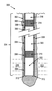
FIG. 3 is a schematic diagram showing an illustrative cementing scenario 300.
In
cementing scenario 300, a drilled borehole 302 is represented as well as a
casing string
304 corresponding to a plurality of casing segments 306 that are connected
together,
resulting in a single long tubular structure. Each casing segment 306 may
correspond to a
hollow steel tube about 30 feet long. Located at the bottom of the casing
string 304 is a
casing shoe 312. Continuing with FIG. 3, the drilled borehole 302 extends into
the earth
where it penetrates a rock formation 310. The open area between the walls of
the drilled
borehole 302 and the casing string 304 is called an annulus 308. During
drilling
operations, the annulus 308 is used to circulate drilling mud. Similarly,
during cementing
operations, the annulus 308 is at least partially filled with cement slurry
(not shown) and
left to harden.
In the cementing scenario 300, the bottom plug 316 and the top plug 314
provide
separators between cleaning fluid 322, cement slurry 320, and drilling mud 318
(assuming further drilling will be performed after the cement has cured). As
pressure is
applied from a pump (not shown) at earth's surface, the bottom plug 316
reaches the
casing shoe 312 and the cleaning fluid 322 is pushed into the borehole 302 and
along the
annulus 308. At this point in the process, the bottom plug 316 blocks further
forward
circulation (reverse circulation is still possible) until the bottom plug 316
is intentionally
ruptured by increasing the pressure of any fluids above the bottom plug 316.
Once the
bottom plug 316 is ruptured, the cement slurry 320 can be pushed into the
borehole 302
and along at least part of the annulus 308 until the top plug 314 reaches the
casing shoe
312 or bottom plug 316. Once the top plug 314 reaches the casing shoe 312 or
bottom
plug 316, the cement slurry 320 in the borehole 302 and along the annulus 308
is given
time to cure before additional drilling operations are initiated.
In different embodiments, the top plug 314, bottom plug 316, and/or the casing
segments 306 may be used to deploy components of the cementing system 200
described
for FIG. 2. As an example, the top plug 314 may include components of the top
plug
position interface 202 and/or the chemical release interface 206. Likewise,
the casing
segments 306 may include components of the top plug position interface 202
and/or the
chemical release interface 206. Further, the bottom plug 316 may include
components of
5
CA 02976102 2017-08-08
WO 2016/148701 PCT/US2015/020995
the top plug position interface 202 and/or the chemical release interface 206.
Many
combinations are possible and are limited only by the particular signaling
option to be
used.
FIGS. 4A, 4B, and 4C are views showing an illustrative top plug, bottom plug,
and casing segment, respectfully. FIG. 4A shows a top plug 402 with electronic
signaling
interface component(s) 404 and chemical release component(s) 406 to perform
signaling
depending on the position of the top plug and/or to release chemicals as
described herein.
In alternative embodiments, the electronic signaling interface component(s)
404 and/or
the chemical release component(s) 406 may be omitted from the top plug 402
(e.g., if a
smart bottom plug and/or smart casing segment is used). FIG. 4B shows a bottom
plug
412 with electronic signaling interface component(s) 414 and chemical release
component(s) 416 to perform signaling depending on the position of the top
plug and/or
to release chemicals as described herein. In alternative embodiments, the
signaling
interface component(s) 414 and/or the chemical release component(s) 416 may be
omitted from the bottom plug 412 (e.g., if a smart top plug and/or smart
casing segment is
used). FIG. 4C shows a cross-sectional view of a casing segment 422 with
electronic
signaling interface component(s) 424 and chemical release component(s) 426 to
perform
signaling depending on the position of the top plug and/or to release
chemicals as
described herein. A plug 430 is also represented in FIG. 4C. The plug 430 may
either be a
top plug 402 or a bottom plug 412. In alternative embodiments, the signaling
interface
component(s) 424 and/or the chemical release component(s) 426 may be omitted
from the
casing segment 422 (e.g., if a smart top plug and/or smart bottom plug is
used).
In the embodiments described in FIGS. 4A, 4B, and 4C, electronic signaling
interface component(s) 404, 414, and 424 may employ technology based on
magnets and
magnetic sensors, electrical switches and electronic sensors, transducers,
electromagnetic
technology, fiber optic cables and sensors, or other proximity detection
equipment, either
passive or active. The electronic signaling interface component(s) 404, 414,
and/or 424
may be deployed in any of several configurations to enable signaling between
the top
plug 402 and the bottom plug 412, signaling between the top plug 402 and the
casing
segment 422, and signaling between the casing segment 422 and the bottom plug
412.
These options may be used independently or together. In addition to sending or
receiving
signals to identify proximity of a top plug to a target position, at least
some of the
electronic signaling interface component(s) 404, 414, and/or 424 operate to
trigger a
response such as releasing chemicals as described herein. In other words, at
least some of
6
CA 02976102 2017-08-08
WO 2016/148701 PCT/US2015/020995
the electronic signaling interface component(s) 404, 414, and/or 424
communicate with
chemical release component(s) 406, 416, and/or 426 in response to receiving a
signal.
The chemical release component(s) 406, 416, and/or 426 may be deployed, and
chemicals
released, in any of several configurations, including in the top plug 402, the
bottom plug
412, and/or the casing segment 422. These options may be applied independently
or
together.
FIG. 5 is a cross-sectional view showing an illustrative bottom plug 500. The
bottom plug 500 includes a chemical release actuator 502, an electronic
signaling
interface 504, a hollow center region 506, a breakable cover 508, a chemical
reservoir
510, a quantity of chemical catalyst 512, and a valve 514. The bottom plug 500
is
designed to fit snugly into the interior of the casing segment 316 (of FIG. 3)
to maintain
isolation between two different fluids located both above and below the
breakable cover
508. The breakable cover 508 is designed to maintain its shape and integrity
while the
bottom plug 500 travels down the wellbore but is designed to break apart when
the
bottom plug 500 stops when it makes contact with the casing shoe 312 (of FIG.
3). In this
manner, the breakable cover 508 isolates a cement slurry from other fluids
present in a
wellbore as the bottom plug 500 travels down a wellbore until the bottom plug
500
reaches a position in contact with the casing shoe 312 (of FIG. 3).
Other embodiments of the bottom plug 500 may include options for allowing the
cement slurry to pass through the bottom plug 500 once it reaches the casing
shoe 312 (of
FIG. 3). These options include using the bottom plug 500 that is broken up in
its entirety
once the bottom plug 500 reaches the casing shoe 312 (of FIG. 3), or employing
a
controllable valve (not shown) on the bottom plug 500 that opens once the
bottom plug
500 reaches the casing shoe 312 (of FIG. 3). Another embodiment includes
making the
bottom plug 500 frangible due to a set pressure threshold or to exposure to
particular
fluids. Other embodiments arc possible.
Once the breakable cover 508 is broken, cement slurry flows through the hollow
center region 506 as the pump 20 (of FIG. 1) maintains pressure on the
wellbore fluids.
At the point where the top plug 402 (of FIG. 4A) reaches a predetermined
position
relative to the bottom plug 500, a signal is sent from the top plug 402 (of
FIG. 4A) to the
bottom plug 500. This signal is received by the electronic signaling interface
504 which
immediately (or after a period of time) activates the chemical release
actuator 502 and
signals the valve 514 to open, allowing fluid communication between the
chemical
reservoir 510 and the hollow center region 506 where the cement slurry is
flowing
7
CA 02976102 2017-08-08
WO 2016/148701 PCT/US2015/020995
through. Once activated, the chemical release actuator 502 injects the
chemical catalyst
into the cement slurry, where the catalyst intermixes with the cement slurry
and is
distributed, intermixed with the cement, into the annulus 308 (of FIG. 3).
FIG. 6 is a flow chart showing an illustrative cementing method. The diagram
describes one preferred embodiment but other embodiments are possible. The
cementing
method includes first installing the bottom plug into the casing string filled
with drilling
mud or cleaning fluid, inserting the cement slurry, and then installing the
top plug. As
additional drilling fluids are pumped into the casing string above the top
plug, the bottom
plug, cement slurry, and top plug are all pushed downward into the casing
string towards
the casing shoe.
In block 602, the bottom plug reaches the bottom of the casing string and
contacts
the casing shoe. The bottom plug will then stop moving. In block 604, since
the column
of materials above the bottom plug, including the cement slurry, top plug, and
fluid are
still in motion, the bottom plug will rupture, allowing the cement slurry to
flow through
the bottom plug and into the annulus of the wellbore. Cement slurry will
continue to flow
into the annulus as the cement slurry and top plug continue their movement
towards the
casing shoe. At block 606, the top plug will reach a predetermined position
along the
casing string. This position may be a set distance from the bottom plug. Once
the top plug
reaches this position, a signal is generated indicating that the top plug has
reached the
desired position. At block 608, the bottom plug receives the signal from the
top plug
indicating that the top plug has reached its desired position. In response to
the received
signal, chemicals are released into the cement slurry flow to accelerate the
cement curing
time. In this manner, the catalyst is distributed in the cement slurry as the
cement slurry
travels around the casing shoe and into the annulus. At block 610, there is a
waiting
period to give time for the cement slurry to cure before the next step in
drilling operations
can begin. The curing time is reduced since the chemical catalyst has been
injected into
the cement slurry. Only the lowest 50-100 feet of cement needs to cure before
drilling
operations may resume. At block 612, the end of the waiting period has passed,
the
cement slurry has hardened or cured, and additional drilling operations may
commence.
Embodiments disclosed herein include:
A: A cementing method comprises positioning a bottom plug at a casing shoe,
rupturing the bottom plug, signaling when a top plug reaches a target position
relative to
the bottom plug, and releasing a chemical into a cement slurry below said top
plug in
8
CA 02976102 2017-08-08
WO 2016/148701 PCT/US2015/020995
response to said signaling, wherein said signaling or said releasing involves
an electronic
signaling interface included with at least one of the bottom plug and the top
plug.
B: A cementing system comprises a top plug position interface that identifies
when a top plug reaches a target position relative to a bottom plug and a
chemical release
interface that releases a chemical into a cement slurry below said top plug in
response to a
release signal from the top plug position interface. The top plug position
interface or the
chemical release interface includes an electronic signaling interface
integrated with at
least one of the top plug and a bottom plug.
Each of embodiments A and B may have one or more of the following additional
elements in any combination: Element 1: wherein said signaling comprising
conveying an
electromagnetic or acoustic signal between the bottom plug and the top plug.
Element 2:
wherein said signaling comprising conveying an electromagnetic or acoustic
signal
between the top plug and a easing segment. Element 3: wherein said signaling
comprising
conveying an electromagnetic or acoustic signal between a casing segment and
the
bottom plug. Element 4: wherein said signaling involves using at least one
mechanical
switch integrated with a casing segment to mark when the top plug reaches the
target
position. Element 5: wherein said signaling involves using at least one
wireless signal
interface integrated with a casing segment to mark when the top plug reaches
the target
position. Element 6: wherein said releasing is performed by the bottom plug in
response
to a signal received from the top plug or a casing segment. Element 7: wherein
said
releasing comprises an actuator opening a passage in the bottom plug or
forcing the
chemical out of the passage to expose the cement slurry to the chemical.
Element 8:
wherein said releasing is performed by a casing segment or the casing shoe in
response to
a signal emitted by the bottom plug or the top plug. Element 9: wherein said
releasing is
performed by a casing segment or a casing shoe in response to a mechanical
trigger
changing its position due to movement of the top plug past the target
position. Element
10: wherein the top plug comprises an electronic signaling interface
configured to
transmit a proximity signal to a casing segment or the bottom plug. Element
11: wherein
the electronic signaling interface includes an acoustic transducer. Element
12: wherein
the top plug position interface comprises a proximity sensor integrated with a
casing
segment. Element 13: wherein the proximity sensor comprises a mechanical
switch
configured to mark when the top plug reaches the target location. Element 14:
wherein
the proximity sensor comprises a wireless signal interface configured to mark
when the
top plug reaches the target location. Element 15: wherein the top plug
position interface
9
CA 02976102 2017-08-08
WO 2016/148701 PCT/US2015/020995
comprises electronic signaling interfaces integrated with both the top plug
and the bottom
plug. Element 16: wherein the bottom plug comprises an electronic signaling
interface
configured to receive the release signal from the top plug or a casing
segment, and
wherein the bottom plug further comprises an actuator that exposes the cement
slurry to
the chemical. Element 17: wherein the chemical release interface comprises a
chemical
reservoir integrated with a casing segment or casing shoe. Element 18: wherein
the
chemical is a liquid, paste, or solid that accelerates a curing time for the
cement slurry.