Note: Descriptions are shown in the official language in which they were submitted.
CA 02976158 2017-08-09
WO 2016/151282
PCT/GB2016/050653
PACKAGE
Background
Food products such as pre-prepared ready meals are packaged ready for heating
in
an oven.
The package comprises a receptacle to hold the food, such as a tray. A lidding
film is
attached to the tray. The film protects the food from the environment, and
gives the food a
useful shelf life. Typically the tray is further packaged within an outer
sleeve, such as a card
sleeve bearing product information.
In use, a user removes the outer packaging, such as the card sleeve, punctures
the
lidding film and then places the package into an oven for heating. After
heating, the lid is
removed and the food is consumed directly from the tray, or transferred from
the tray before
consumption.
It is known to attach the lidding film to the rim of the tray by a resealable
adhesive.
However, the failure rate of this type of package is relatively high. Rough
handling during
transit, or at a point of sale, can cause the lid to separate from the tray,
spoiling the contents
of the package.
Another known way of attaching the lidding film to the rim of the tray is by a
welded
seal. This provides a stronger, more reliable, seal but has a disadvantage
that the lidding film
can shred when a user tries to remove the film from the tray after heating.
There is a requirement for alternative packaging.
Summary
This Summary is provided to introduce a selection of concepts in a simplified
form
that are further described below in the Detailed Description. This Summary is
not intended to
identify key features or essential features of the claimed subject matter, nor
is it intended to
be used as an aid in determining the scope of the claimed subject matter.
An aspect of the disclosure provides an ovenable package comprising:
an ovenable receptacle configured to hold a food product, the receptacle
having an
open face surrounded by a rim;
an ovenable laminated film lid attached to the rim of the receptacle by a
welded seal
between a lower face of the laminated film lid and the rim of the receptacle,
the welded seal
extending continuously around the rim of the receptacle, the laminated film
lid comprising at
least:
a first layer;
1
CA 02976158 2017-08-09
WO 2016/151282
PCT/GB2016/050653
a second layer above the first layer;
a cut line in the first layer but not the second layer, the first cut line
offset
inwardly from the rim of the receptacle to define a peripheral portion of the
first layer between
the cut line and an outer perimeter of the lid and an inner portion of the
first layer within the
cut line;
a resealable adhesive between at least the peripheral portion of the first
layer
and the second layer;
wherein an unopened package is openable by separating the second layer from
the first layer
in the peripheral region, and wherein the opened package can be reclosed to a
ventable state
by reattaching the second layer to the peripheral region of the first layer by
the resealable
adhesive, wherein the ventable state permits venting of gas from an interior
of the receptacle
between the second layer and the peripheral region of the first layer.
The resealable adhesive may be more strongly attached to the second layer than
the
first layer such that the resealable adhesive is carried by the second layer
when the second
layer is separated from the first layer.
The inner portion of the first layer may be a flap, the cut line defining an
open path
with a first end point and a second end point.
The cut line may form a closed path.
The laminated film lid may extend beyond the rim of the receptacle.
The laminated film lid may comprise a tab portion, the film lid extending
beyond the
rim by a greater distance at the tab portion compared to the remainder of the
film lid.
The cut line may be offset inwardly from the rim by a larger distance
proximate the
tab portion.
The tab portion may be located at a corner of the receptacle, wherein the cut
line is
offset inwardly from the rim by a larger distance at the corner.
Only a resealable adhesive may be provided between the first layer and the
second
layer.
A bond strength of the resealable adhesive may be lower on the peripheral
portion of
the first layer compared to the inner portion of the first layer.
Resealable adhesive may be provided between the peripheral portion of the
first layer
and the second layer, and a permanent adhesive is provided between the inner
portion of the
first layer and the second layer.
The laminated film lid may be printed on an outer face of the second layer.
The laminated film lid may be printed between the second layer and the first
layer.
2
CA 02976158 2017-08-09
WO 2016/151282
PCT/GB2016/050653
The laminated film lid may be printed between the second layer and the first
layer
only above the inner portion of the first layer.
Another aspect of the disclosure provides an ovenable laminated film lid
configured to
attach to a rim of an ovenable receptacle to hold a food product, the ovenable
laminated film
comprising:
a first layer configured to seal to the rim of the receptacle;
a second layer above the first layer;
a cut line in the first layer but not the second layer, the first cut line
offset inwardly
from the rim of the receptacle to define a peripheral portion of the first
layer between the cut
line and an outer perimeter of the lid and an inner portion of the first layer
within the cut line;
a resealable adhesive between at least the peripheral portion of the first
layer and the
second layer;
wherein the lid is openable by separating the second layer from the first
layer in the peripheral
region, and wherein the lid can be reclosed to a ventable state by reattaching
the second
layer to the peripheral region of the first layer by the resealable adhesive,
wherein the
ventable state permits venting of gas from an interior of the receptacle
between the second
layer and the peripheral region of the first layer.
In this specification, the term "resealable adhesive" means an adhesive which
allows
two surfaces to adhere to one another and which also allows the surfaces to be
separated
non-destructively from one another and to re-adhere to one another. An example
of a
resealable adhesive is a Pressure Sensitive Adhesive (PSA), such as a peelable
PSA, where
an adhesive bond is achieved by applying pressure to the adhesive.
In this specification, the term "ovenable package" means the package is formed
of an
oven grade material which is capable of withstanding heating in an oven, such
as a
conventional oven (gas, electric) or microwave oven for a cooking period.
Typically the
cooking period is less than one hour.
In this specification, the term "resealed" means that two surfaces can be
refastened
to one another. A degree of sealing may be achieved between the two surfaces
when they
are refastened to one another. However, the term "resealed" does not require
the two
surfaces to form a fully airtight seal during the subsequent fastening of the
surfaces.
The preferred features may be combined as appropriate, as would be apparent to
a
skilled person, and may be combined with any of the aspects of the invention.
3
CA 02976158 2017-08-09
WO 2016/151282
PCT/GB2016/050653
Brief Description of the Drawings
Embodiments of the invention will be described, by way of example, with
reference to
the following drawings, in which:
Figure 1 shows an ovenable package;
Figure 2 shows a cross-section through the package of Figure 1;
Figure 3 shows a top view of the package of Figure 1;
Figure 4 shows layers of laminated film lid of the package;
Figures 5A-5D show a sequence of states during use of the package;
Figure 5E shows an alternative package with an adhesive layer across the film
lid;
Figure 6 shows an example of a package with a removable lid;
Figures 7A and 7B show examples of a package with an anti-scald feature;
Figures 8A-8D show examples of cut lines;
Figure 9 shows two alternative ways of printing the package;
Figure 10 shows a package with printing;
Figure 11 shows a package with multiple compartments;
Figure 12 shows another package with multiple compartments.
Common reference numerals are used throughout the figures to indicate similar
features.
Detailed Description
Embodiments of the present invention are described below by way of example
only.
These examples represent the best ways of putting the invention into practice
that are
currently known to the Applicant although they are not the only ways in which
this could be
achieved. The description sets forth the functions of the example and the
sequence of steps
for constructing and operating the example. However, the same or equivalent
functions and
sequences may be accomplished by different examples.
Figures 1 to 3 show an example ovenable package 5. The package 5 comprises an
ovenable receptacle 10 and an ovenable lidding film 20. The receptacle 10 can
be in the form
of a tray, pot, tub or similar receptacle for holding a food product. An
embodiment will be
described where the receptacle is a tray 10. The tray 10 can be rectangular
(as shown),
square, circular, oval or any other desired shape. The ovenable receptacle is
formed of an
oven grade material. The oven grade material can withstand heating in an oven
for a typical
cooking period, without melting or deforming. Similarly, the ovenable lidding
film is formed of
4
CA 02976158 2017-08-09
WO 2016/151282
PCT/GB2016/050653
an oven grade material. The oven grade material is able to withstand heating
in an oven for a
typical cooking period without melting. Typically, food is heated in a
conventional gas or
electric oven at temperatures up to 220 C for a period of up to one hour.
Examples of
suitable oven grade materials for the receptacle 10 are Crystalline
Polyethylene
Terephthalate (CPET), bagasse, carton board (coated/uncoated), pulp trays.
Examples of
suitable oven grade materials for the lidding film 20 are polyester based
film, such as
Polyethylene terephthalate (PET), polyactic acid (PLA) film, cellulose, or any
other suitable
oven-grade polymer. The film should not become brittle, melt or release toxins
when
subjected to temperatures up to 220 C.
The tray 10 has a base 11, a peripheral wall 12 and a rim or flange 14. The
base 11
and peripheral wall 12 define an interior volume 13 for holding a quantity of
a food product.
The base 11 allows the package to remain upright when it is heated in an oven.
The food
product may comprise any kind of food product, such as a pre-prepared meal,
vegetables,
fruit, meat or fish. A lidding film 20 is attached to the top face of the tray
10. The lidding film
20 is attached to the rim 14 of the tray 10. As will be described in more
detail below, the
lidding film 20 is a multi-layer laminate comprising at least two layers 21,
22. The lower layer
21 of the lidding film 20 is sealed 15 to the rim 14 of the tray, such as by a
welded seal. The
seal 15 is continuous around the rim 14 of the tray 10. Adhesive is present
between the
lidding film 20 and the rim 14. The adhesive can be heat seal adhesive. This
is a non-
resealable non-tacky adhesive which is typically coated onto the lidding film.
A welded seal is
formed by applying heat to the lidding film where the lidding film overlies
the rim 14 of the
tray. This creates a permanent seal. The heat seal adhesive can be locally
applied where a
seal is required (i.e. a region of the lidding film where the lidding film
will overlie a rim of a
tray) or the heat seal adhesive can be applied as a layer across the entire
underside of the
lidding film. Providing a fully coated lidding film can save tooling costs
incurred when pattern
applying. An example thickness of the heat seal is 0.5-15pm.
The first, lower, layer 21 of the lidding film 20 has a cut line 25. The cut
line 25 is
offset inwardly from the rim 14 of the tray. The cut line 25 defines: (i) a
peripheral portion 31
of the first layer 21 between the cut line 25 and an outer perimeter of the
lid 20; and (ii) an
inner portion 32 of the first layer 21 within the cut line 25. In the example
of Figure 3, the cut
line 25 is defined along substantially three sides of the tray. The cut line
25 defines an inner
portion 32 of the first layer 21 which is a flap. In the example of Figure 3,
the ends 25A, 25B
of the cut line 25 are curved back along the direction of the cut line 25
through 180 degrees.
This helps to prevent opening of the first layer beyond the end of the cut
line 25 during an
initial opening.
The lidding film 20 has a tab 28 which a user can grasp to open the package.
For a
square or rectangular package, as shown in Figures 1 to 3, the tab can be
located at a corner
of the package. The tab 28 is a portion of the lidding film which extends
beyond the rim for a
5
CA 02976158 2017-08-09
WO 2016/151282
PCT/GB2016/050653
larger distance than at other points around the rim. The tab 28 extends beyond
the rim by a
distance which is sufficient for a user to grasp.
Figure 4 separately shows the layers 21, 22 of the lidding film 20. In this
specification
the terms "lower", "lowest", "higher", "highest", "above" and "below" are used
to describe the
layers of the lidding film with respect to a tray lying on a horizontal
surface. Layer 21 is the
lowest layer, for attaching to the tray 10. Layer 22 is above layer 21 in the
assembled
laminate. The cut line 25 is defined in layer 21 but not layer 22. A lower
surface of layer 21
can carry a line of heat seal adhesive 15 for use in forming the welded seal
with the rim of the
tray 10. Layer 22 does not have any cut lines. A resealable adhesive, such as
a peelable
pressure sensitive adhesive (PSA) 23, is provided between layers 21, 22. The
resealable
adhesive may be present across the entire region between layers 21 and 22.
Alternatively,
the resealable adhesive may be present only in the peripheral region 31 where
a resealable
seal is required. In other regions a permanent laminating adhesive can be
used. In use, the
second layer 22 can be peeled away from the first layer 21. The second layer
22 separates
from the first layer 21 in the peripheral region 31. The second layer 22
remains laminated to
the first layer 21 in the inner region 32, so that when the lid is opened a
user can gain access
to the tray.
The layers 21, 22 can be formed of the same material (e.g. PET or similar) or
they
can be formed of different materials. An example range of thicknesses for each
layer 21, 22
is 12-200pm. For a package which is intended for storage in a freezer, the
ovenable lidding
film should also be capable of withstanding low temperatures, such that the
material is able to
withstand an overall temperature of, for example, -40 C to +220 C.
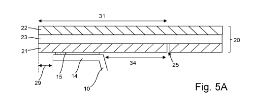
Figures 5A to 5C show a sequence of opening the package. The detail of the
region
along cross-section A-A', through the rim of the tray, is shown in these
drawings. Figure 5A
shows the package in an initial, unopened, state. The lidding film 20 extends
a short distance
beyond the rim 14 of the tray 10. A lower face of the lidding film 20 is
sealed to the rim 14 of
the tray 10 by adhesive 15. Layers 21, 22 are laminated together by resealable
adhesive 23.
The first layer 21 has a cut line 25. In this example, the cut line 25 extends
fully through the
layer 21. The resealable seal provides an airtight seal to the package until
the lidding film is
first opened. The contents of the tray 10 are protected from the surrounding
environment.
Typically, the package is stored in a chilled or frozen environment (e.g.
fridge or freezer)
before heating. The package may be defrosted before heating, or heated
directly from frozen.
Alternatively, the package may be stored in an ambient environment before
heating.
Figure 5B shows the package in an initially opened state. A user opens the
package
in this way prior to heating the package. A user grasps the lidding film 20,
such as by
grasping the tab region 28, and then lifts the lidding film away from the tray
10. This causes
the upper layer 22 to separate from the lower layer 21 in region 33, as far as
cut line 25. This
6
CA 02976158 2017-08-09
WO 2016/151282
PCT/GB2016/050653
separation occurs because the opening force applied by the user is greater
than the bond
strength of the resealable adhesive 23. In this example, the resealable
adhesive 23 is more
strongly attached to the second layer 22 than the first layer 21 such that the
resealable
adhesive 23 is carried by the second layer 22 when the second layer is
separated from the
first layer, as shown here. In an alternative example, the adhesive can remain
attached to
lower layer 21. Inwardly of the cut line 25, the upper layer 22 remains
laminated to the lower
layer 21. The inner portion 32 of the first layer 21 remains laminated to the
second layer 22.
At the tab 28, and near to the tab, the outermost portion 21A of layer 21 will
remain
attached to the adhesive 23 and upper layer 22 (as shown in Figure 5B). The
lower layer 21
will rupture at point 27, leaving an irregular edge to the severed parts of
the first layer 21.
This provides evidence that the package has been opened. Further away from the
tab 28,
when the lid is pulled back, the outermost portion 21A of layer 21 may
separate through the
break at 27, which occurs due to the bond at heat seal 15 being stronger than
layer 21 itself.
In this case, at some point around the rim 14 there will be a transition
between the place
where the outermost portion 21A of layer 21 is present and a place where the
outermost
portion 21A of 21 is not present. This also provides evidence that the package
has been
opened. The lid 20 may be pulled back along the full extent of the cut line
25, or for a lesser
extent of the cut line 25.
After pulling back the lidding film 20 as shown in Figure 5B, the user
recloses the
lidding film 20. The user may lightly run their finger along the lid 20 in the
region where the
second layer 22 of the lidding film 20 separated from the peripheral region 31
of the first layer
21, or may brush their hand across the lidding film 20 in a sweeping action.
This can help to
re-attach the second layer 22 of the lidding film 20 separated from the
peripheral region 31 of
the first layer 21. Figure 5C shows this ventable state of the package. Figure
5C is similar to
Figure 5A. In region 33 the second layer 22 re-attaches to the first layer 21
due to the
resealable adhesive 23. The offsetting of cut line 25 inwardly from the rim 14
provides a
region where the first layer 21 can be re-attached to the second layer 22.
However, due to
the initial opening of the lidding film at Figure 5A, the bond strength of the
seal in region 33 is
weakened. This reduction in bond strength is desirable, as the lid only needs
to re-attach to
the first layer to hold the lid in place. The reduced bond strength permits
venting. Another
difference compared to Figure 5A is that the first layer 21 will be ruptured
27 around at least
some of the perimeter of the lid. This provides evidence of tampering.
Subsequent to Figure 5C, the package is heated in an oven. During heating, gas
can
safely vent from the interior volume of the package. The second layer 22 can
separate from
the first layer 21 in region 33 to allow gas to vent. The lidding film
continues to cover the tray.
This prevents food escaping from the package, such as hot liquid splashing the
interior of the
oven.
7
CA 02976158 2017-08-09
WO 2016/151282
PCT/GB2016/050653
At some point during the heating process, the package may be removed from the
oven to stir the contents. The lid 20 can be pulled back, similar to as shown
in Figure 5B, and
then reclosed as shown in Figure 5C and returned to the oven. An advantage of
the package
is that the lid can be secured back to the package after opening, thereby
preventing
splashing.
At the end of the heating process the package is removed from the oven. The
lid 20
is fully pulled back. It is also possible to remove the lid from the tray 10
by pulling the lid fully
back. Figure 50 shows a plan view of the tray after the lid has been removed
from the tray.
Pulling the lid back beyond the end of cut line 25 will severe through both
layers 21, 22 of the
lid along path 36, leaving only the peripheral portion 31 of the lid attached
to the rim of the
tray 10. This is particularly useful when the contents of the tray require
pouring from the tray.
The lip 31 of lidding film is not present in region 37 after removal of the
lid. This allows easy
pouring from the hinge end of the tray in region 37. The food contents can be
consumed from
the tray 10, or can be transferred from the tray 10 before consumption.
Another advantage of the package is that it can allow the package to be opened
(at
Figure 5B) to remove an item from the interior of the package before heating.
For example,
some pre-prepared food has an item which requires a shorter heating time than
the remainder
of the package. In a conventional package this need to pull back the lidding
film to remove
the item can cause splashing and/or poorer heating of the food when the opened
package is
heated.
For completeness, Figure 5E shows another example of the package with a
lidding
film 20 having heat seal adhesive 15 applied as a layer across the lidding
film.
A non-limiting example range of bond strength for the resealable adhesive 23
in the
initial unopened state is 100g-400g per 25mm. This reduces after the package
is initially
opened. A non-limiting example range of bond strength for the resealable
adhesive 23 in the
ventable state is 50g-100g per 25mm.
Figure 6 shows an example of a package with a removable lid. The cut line 25
follows a closed path. The cut line 25 is offset from the rim 14 around the
full perimeter of the
rim. The lid operates as previously shown in Figures 5A to 5C. When the lid is
first opened, it
is pulled back, but not separated from the tray 10. When the food is ready for
consumption,
the lid 20 can be fully pulled back and removed from the tray 10.
Figures 7A and 7B show an anti-scald feature of a package. In Figure 7A, only
the
corner of a package is shown. The peripheral portion 31 of the first, lower,
layer 21 is defined
by a cut line 25. The cut line 25 is offset by a distance 01 from the rim 14
and heat seal 15
around the tray. The lidding film 20 has a tab 28 which a user can grasp to
open the
package. In a region adjacent the tab 28, the cut line is offset by a larger
distance from the
rim 14 and heat seal 15. In the example of Figure 7A, the cut line 25 does not
follow the
8
CA 02976158 2017-08-09
WO 2016/151282
PCT/GB2016/050653
shape of the rim at the corner but, instead, follows a diagonal path at the
corner. The cut line
is offset by an increased distance of up to 02 from the rim 14, where 132>131.
This larger
offset provides scald protection to a user because the user's fingers are
separated by a larger
distance from any hot gases which escape from the package when the film is
pulled back.
The scalding risk is reduced.
While Figure 7A shows a cut line offset by an increased distance at a corner
of a
receptacle, the cut line may be modified in this way at any position around
the receptacle.
Figure 7B shows an example of a receptacle which is circular in plan view. The
cut line 25 is
offset by a distance 01 from the rim 14 and heat seal 15 around most of the
circumference of
the rim. The cut line 25 is offset by an increased distance of up to 02
adjacent a tab 28 on
the lid. The same benefit of reduced scalding is obtained. The package shown
in Figures 7A
or 7B can be combined with the features of any of the other described
packages.
In the above examples, a cut line 25 is formed in the first layer 21. Figure
8A shows
a cross-section through the first layer 21 and a plan view of the first layer
21. Figure 8A
shows a cut line 25 which is continuous along the surface, as shown in the
plan view. The cut
line extends fully through the layer, as shown in the cross-section A-B. As
there is a
continuous cut fully through the layer, the layer will easily separate along
the cut line 25.
Figures 8B-80 show some other examples of cut lines 25 which can be formed in
the
first layer 21 of the laminate lid 20. Each of Figures 8B-80 show a cross-
section through the
first layer 21 and a plan view of the first layer 21. The example cut lines
shown in Figures 8B-
80 can provide improved evidence of when the package has been tampered with.
Figure 8B shows a cut line 25 which is discontinuous along the surface, as
shown in
the plan view. This type of cut line is a perforated cut line. This type of
cut line is an example
of a line of weakness. The cut line comprises non-perforated portions 51 where
the layer has
not been cut and remains intact, as shown in the cross-section A-B. The cut
line also
comprises perforated portions 52 where the cut line extends fully through the
layer, as shown
in the cross-section C-D. The layer is weakened along the cut line. When a
force is applied
to the cut line by applying an opening force to the lid, the force will
rupture the non-perforated
portions 51 and the layer will separate along the cut line 25.
Figure 8C shows a cut line which is continuous along the surface, as shown in
the
plan view. The cut line extends partially through the layer, as shown in the
cross-section A-B.
This type of cut line is a score line or scribe line. This type of cut line is
an example of a line
of weakness. The layer is weakened along the cut line. When a force is applied
to the line of
weakness by applying an opening force to the lid, the force will rupture the
cut line.
Figure 80 shows a cut line which is continuous along the surface, as shown in
the
plan view. The cut line extends partially through the first layer. The depth
of the cut varies
along the cut line. Two cross-sections are shown. At cross-section A-B the cut
extends a first
9
CA 02976158 2017-08-09
WO 2016/151282
PCT/GB2016/050653
depth into the layer. At cross-section C-D the cut extends a second depth into
the layer. The
second depth is greater than the first depth. This type of cut line can be
called a crenellated
line. The line can alternate between the cut depths shown in the two cross-
sections along the
length of the line. The first depth may be zero, such that the line has some
portions which are
not cut at all, and some portions where the cut line extends partially into
the layer. The layer
is weakened along the cut line. When a force is applied to the line of
weakness by applying
an opening force to the lid, the layer will separate along the line of
weakness.
In any of the examples, the cut line 25 may be formed by a laser cutting
machine, or
by a die cutting machine. The cut line may be formed in the first layer 21
before laminating
the layers 21, 22 together. Alternatively, it is possible to form the cut line
25 after lamination
of the layers 21, 22.
The package 5 may comprise a sleeve which fits around the tray 10. The sleeve
may
provide protection to the package, and carry information about the contents,
such as product,
branding, weight, ingredients, nutritional information, recycling information,
regulatory
information. The lidding film 20 of the package may carry printing. Figure 9
shows two ways
in which the package may be printed. The printing may be provided 62 on an
external face of
the upper (outer) layer 22. Alternatively, the printing may be provided 63 on
an inner face of
the upper (outer) layer 22. The upper layer 22 can be reverse printed before
the second layer
22 is laminated to the first layer 21. Advantageously, the printing 63 can be
restricted to a
region of the lidding film within the cut line 25, or within a region which is
offset from the cut
line 25 by a defined distance. This is shown by printing 61 in Figure 10. This
can help
prevent any migration of chemicals used for the printing into the interior of
the package, as
the printing will remain within the laminated region of the lidding film 20.
The example packages illustrated so far have a single compartment for holding
a
food product. Any of the features described above can be applied to a package
having
multiple compartments. Figures 11 and 12 show examples of packages with more
than one
compartment. Figure 11 shows a package similar to the one shown in Figure 2. A
dividing
wall 43 within the receptacle (e.g. tray) divides the receptacle into two
compartments 41, 42.
The dividing wall 43 can extend up to the height of the rim 14, or can be of a
lower height than
the rim 14. Figure 12 shows another package. A dividing wall 44 within the
receptacle (e.g.
tray) divides the receptacle into two compartments 41, 42. In this example,
the dividing wall
44 extends up to the same height as the rim 14. The lidding film 20 is
attached to the top
surface of the dividing wall 44. A welded seal 45 is formed between a lower
face of the
lidding film 20 and the dividing wall 44. The welded seal 45 can be continuous
with the
welded seal 15 around the outer rim of the receptacle. In the example shown in
Figure 12, a
first compartment 41 nearest the tab has a cut line 25C with a closed path and
a second
compartment 42 furthest from the tab has a cut line 25D with defined ends 25A,
25B. In use,
when the tab is pulled, the second layer separates from the first layer to
leave a peripheral
CA 02976158 2017-08-09
WO 2016/151282
PCT/GB2016/050653
region 31 around the first compartment 41 and a peripheral region 31 around
the second
compartment 42. The second layer of the lidding film separates from the first
layer of the
lidding film above the dividing wall 44. In Figures 11 and 12, the dividing
wall 43, 44 may
have a different size, shape (e.g. non-linear) and/or position to the one
shown. A larger
number of dividing walls 43, 44 can be provided, to provide a larger number of
compartments.
A package having two layers has been described above. It is possible to add
one or
more further layers to the laminate.
The lidding film 20 can be supplied in the form of a web or reel of laminate
material.
The web is a continuous length of laminate material. The web can be divided
into individual
pieces to provide the lidding film for an individual package. The heat seal
adhesive can be
applied to the web at the time of manufacture, or at a later point in time,
such as when printing
an exterior surface of the film, or just prior to forming the package.
In any of the examples of the package, the resealable adhesive can be an oven
grade PSA.
It will be understood that the benefits and advantages described above may
relate to
one embodiment or may relate to several embodiments. The embodiments are not
limited to
those that solve any or all of the stated problems or those that have any or
all of the stated
benefits and advantages.
Any reference to 'an' item refers to one or more of those items. The term
'comprising'
is used herein to mean including the method blocks or elements identified, but
that such
blocks or elements do not comprise an exclusive list and a method or apparatus
may contain
additional blocks or elements.
The steps of the methods described herein may be carried out in any suitable
order,
or simultaneously where appropriate. Additionally, individual blocks may be
deleted from any
of the methods without departing from the spirit and scope of the subject
matter described
herein. Aspects of any of the examples described above may be combined with
aspects of
any of the other examples described to form further examples without losing
the effect sought.
It will be understood that the above description of a preferred embodiment is
given by
way of example only and that various modifications may be made by those
skilled in the art.
Although various embodiments have been described above with a certain degree
of
particularity, or with reference to one or more individual embodiments, those
skilled in the art
could make numerous alterations to the disclosed embodiments without departing
from the
spirit or scope of this invention.
11