Note: Descriptions are shown in the official language in which they were submitted.
VISIBLE VALVE SYSTEM AND SPILL REDUCING SYSTEM
[0001] <Blank>
FIELD OF THE DISCLOSURE
[0002] The present disclosure relates generally to breastmilk expression
systems and, more
particularly, to breastmilk expression systems including a spill reducing
system. The spill
reducing system can be partially or fully incorporated into a visible valve
system for facilitating
media flow from a conduit to a container, such as a bottle, a bag, or other
suitable receptacle.
BACKGROUND
[0003] Nursing mothers, and in particular first-time nursing mothers, face a
number of
distractions and challenges associated with successfully nursing their babies.
Breast pumps can
be used by mothers to generate breastmilk for feeding their babies at a later
time. While various
breast pumps have provided nursing mothers with the ability to pump breastmilk
for later
feedings, kits that mothers connect to breast pumps have a number of small
parts that can
become lost, or that the nursing mothers may simply forget to properly
assemble. One small part
that can easily become lost from a kit is a valve that is commonly used to
provide media
communication from a conduit to a container for collecting the breastmilk.
Additionally, even
when the valve is in place in the kit, the kit can tip over during a pumping
session causing the
breastmilk to spill out of the container.
1
Date Recue/Date Received 2022-07-07
CA 02976164 2017-08-09
WO 2016/128831 PCT/1B2016/000209
SUMMARY OF THE DISCLOSURE
[0004] In accordance with the principles of the present disclosure a spill
reducing breastshield
assembly for a breastmilk expression system is set forth. The breastshield
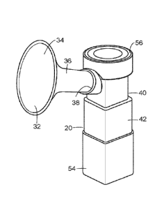
assembly is
configured to attach to a container, and can include a removable, visible
valve system. The
visible valve system is not only easily assembled by the user, but also
provides a visible
indication to the user that the system is properly assembled. As the teini
"visible valve system"
is used herein, it refers to a valve assembly of a breastmilk expression
system that has an external
portion, or outer member, which is directly visible (i.e., not through some
other component such
as a collection container) by a user from an exterior of the breastmilk
expression system when
assembled, and during pumping and milk collection, even if a valve mechanism,
or inner valve
member, of which may not be visible in that configuration. The visible valve
system is a visible
component that can easily be correctly assembled within the breastmilk
expression system to
serve its intended purpose. Additionally, the visible valve system can serve
as a spill reducing
system, or a component of a spill reducing system for the breastmilk
expression system.
Alternatively, the spill reducing system can be incorporated elsewhere in a
breastmilk expression
system.
[0005] Various exemplary visible valve systems are disclosed herein that are
suitable for use
with breastmilk expression systems, although numerous variations of the
embodiments and other
embodiments are contemplated in accordance with the principles of the present
disclosure. For
example, in one exemplary spill reducing breastshield assembly for a
breastmilk expression
system, the breastshield assembly is configured to attach to a container, and
can include a breast
interface, such as a funnel-shaped breastshield. The breast shield can be
removably securable to
a breastshield mount, or conduit, that cooperates with such other components
as a cap and a
suitable container for collecting breastmilk.
[0006] Any suitable connection can be formed between the conduit and the
visible valve
system. In one exemplary embodiment, the conduit may be provided with one or
more plug
elements, each of which can be received in one or more slots of the visible
valve system, if
desired. For example, where the conduit includes threaded plug elements, the
container for
collecting breastmilk can include thread segments that cooperate with the
threaded plug
2
CA 02976164 2017-08-09
WO 2016/128831 PCT/1B2016/000209
element(s) of the conduit when the threaded plug elements are selectively
seated within the
visible valve to threadedly engage a threaded region of the container.
[0007] In an embodiment, the conduit may include a breastmilk-receiving
cavity, or media
separation well, at least partially defined by a valve seat. An opening is
provided in the valve
seat. The opening can be closed by a valve member when sufficient negative
pressure is applied
to the system to extract breastmilk, which milk is temporarily collected in
the media separation
well. The valve can be preloaded so as to be biased in a closed condition,
i.e. in sealing
engagement with the valve seat. The media separation well can direct media
flow through the
conduit when the breastmilk expression system is fully assembled with the
visible valve system,
and in use. When the system pressure undergoes certain changes in conditions,
the valve
member opens, peimitting breastmilk in the media separation well to pass
through the opening
and into the container.
[0008] The visible valve system can be a one piece (i.e., integral) component
of a breastmilk
expression system and can include an outer member and an inner valve member.
The inner valve
member can be connected to, or integrally formed with, the outer member. The
visible valve
system can be configured to detachably fit, either directly or indirectly, an
attachment or docking
portion of each of the container and the conduit. The visible valve system may
be disposed
intermediate the conduit and the container. As a result, the inner valve
member can be
assembled and removed from the system without the user needing to handle, or
make any
physical contact with, the inner valve. Further, by forming the inner valve
integrally in the valve
system, the entire valve system is easy to clean, and the likelihood that the
inner valve member
alone will become misplaced or forgotten when assembling the breastmilk
expression system is
eliminated.
[0009] The visible valve system can include at least one vent between the
outer member and
the inner valve member. The vent may vent air from the container to the
atmosphere, or provide
a portion of a channel that vents air from the container to the atmosphere.
The visible valve
system may further be provided with structural elements that form all or a
portion of a spill
reducing tortuous path for breastmilk. The spill reducing tortuous path can
reduce spillage of
breastmilk during use of the spill reducing breastshield assembly for a
breastmilk expression
system. The spill reducing tortuous path can be formed by connecting the
visible valve system to
3
CA 02976164 2017-08-09
WO 2016/128831 PCT/1B2016/000209
the breastmilk expression system, and any suitable variation in the
configuration of the visible
valve system or conduit can be made to achieve the spill reducing tortious
path upon assembly.
The spill reducing tortuous path can include any structure that creates
increased resistance to
flow in the system, such as by bending, redirecting, or otherwise creating
back pressure to limit
liquid flow from a container connected to the visible valve system through the
path.
[0010] Alternatively, a spill reducing tortuous path can be formed elsewhere
in the breastmilk
expression system, with or without inclusion of the visible valve system. For
example, the spill
reducing tortuous path can be formed in the conduit, container, or in a
separate component
adapted to be fitted to the breastmilk expression system.
[0011] When the spill reducing tortuous path is provided wholly or in part by
a visible valve
system constructed in accordance with the principles herein, the path can be
provided in a variety
of configurations to redirect media flow from the container. For example, the
visible valve
system can include a series of incomplete annular ribs that project from the
visible valve system,
with gaps of adjacent incomplete annular ribs offset from one another, such as
by a center-to-
center separation of some distance or, in the case of a round visible valve
system, by one or more
varied angles, thereby defining a spill reducing tortuous path to limit
leakage, in the event the
breastmilk system is tipped over. Other structural arrangements that inhibit
liquid flow can be
incorporated into the conduit such that assembly of the visible valve system
to the conduit forms
the spill reducing tortuous path. Further, any configuration wherein the
breastmilk expression
system assembled with the visible valve system forms a spill reducing tortuous
path that limits
leakage in the system from a container connectable to the breastmilk
expression system is within
the scope of the present disclosure.
[0012] In certain embodiments, the inner valve member is further defined by an
interchangeable, visible inner valve member.
[0013] In certain embodiments, the visible valve system for a breastmilk
expression system
includes an externally accessible outer member that can be configured for
selective connection to
one or both of a conduit and a container. It would be visibly apparent to the
user that the outer
member is missing or misassembled between the conduit and the container, which
advantageously serves to facilitate proper assembly of the various components
of the system.
4
[0014] The visible valve system can further include an inner valve member
connected to the
outer member. The outer member also serves to isolate the inner valve member
from external
contact and contaminants. For instance, after cleaning of the visible valve
system, a user can
avoid inadvertently touching the inner valve member.
[0015] In certain embodiments, the visible valve system includes an integrally
formed inner
valve member connected to the outer member. As with other embodiments
described herein, it
would be visibly apparent to the user that the outer member is missing or
misassembled between
the conduit and the container.
[0016] A visible valve system for a breastmilk expression system of certain
embodiments of
the present disclosure includes an outer member configured to be grasped by a
human hand
during use of the breastmilk expression system when selectively assembled in
the breastmilk
expression system, and an inner valve member connectable to the outer member
to a position
within a media flow during operation of the breastmilk expression system. The
outer member
may be larger than the inner valve member, allowing the user to more readily
grasp the outer
valve member with several fingers, if desired, and place the visible valve
system in its intended
position during assembly of the breastmilk expression system, while minimizing
needed
dexterity to place a valve member in its proper location.
[0016a] In one broad aspect, there is provided a valve system connectable to a
container of a
breastmilk expression system, the valve system comprising: an inner valve
member through
which media can flow into the container; and an outer member connected to the
inner valve
member, the outer member including a spill-reducing tortuous path, the
tortuous path including a
region surrounding the inner valve member that constricts from a first cross-
sectional area to a
second cross-sectional area that is smaller than the first cross-sectional
area more distant from
the container, wherein the outer member is directly visible from an exterior
of the breastmilk
expression system when the breastmilk expression system is assembled, and the
outer member
includes a first end and a second end disposed opposite to the first end, the
first end adapted to be
removably attached to a conduit and the second end adapted to be attached to a
container.
[0016b] In another broad aspect, there is provided a method of reducing
spillage for a
breastmilk expression system, the method comprising: producing a breastmilk
collection kit
having a conduit, a container and a valve, the valve including an inner valve
member through
5a
Date Recue/Date Received 2022-07-07
which media can flow into a container and an outer member connected to the
inner valve
member, the outer member including a spill-reducing tortuous path, the
tortuous path including a
region surrounding the inner valve member that constricts from a first cross-
sectional area to a
second cross-sectional area that is smaller than the first cross-sectional
area more distant from
the container; and configuring the outer member to be connectable to the
container so that the
system is capable of reducing a flow rate in the container and to be directly
visible from an
exterior of the breastmilk expression system when the breastmilk expression
system is
assembled, the outer member including a first end and a second end disposed
opposite to the first
end, the first end configured to be removably attached to a conduit and the
second end
configured to be attached to a container.
BRIEF DESCRIPTION OF THE SEVERAL VIEWS OF THE DRAWINGS
[0017] FIG. 1 is a schematic view of a duckbill inner valve for use in a
visible valve system
constructed in accordance with the principles of the present disclosure, the
duckbill inner valve
providing selective media communication between a conduit and a container such
as a milk
collecting container;
[0018] FIG. 2 is a bottom view of a cantilevered flap inner valve for use in a
visible valve
system constructed in accordance with the principles of the present
disclosure;
[0019] FIG. 3 is a bottom view of an inner valve in the form of a disc-shaped
media valve for
use in a visible valve system constructed in accordance with the principles of
the present
disclosure;
5b
Date Recue/Date Received 2022-07-07
CA 02976164 2017-08-09
WO 2016/128831 PCT/1B2016/000209
[0020] FIG. 4 is a schematic view of an inner valve which may be a suitably-
styled inner
valve for use in a visible valve system constructed in accordance with the
principles of the
present disclosure;
[0021] FIG. 5 is a perspective view of a breastmilk expression system having a
visible valve
system constructed in accordance with the principles of the present
disclosure, the visible valve
system assembled between a conduit and a container;
[0022] FIG. 6 is an exploded view of a visible valve system intennediate a
container and an
engagement portion of a conduit, the visible valve system configured to
detachably fit an outer
member to form a substantially continuous connection between a milk collecting
container and a
conduit;
[0023] FIG. 7 is a view taken along lines 7-7 of FIG. 6, illustrating a valve
seat of the conduit
and an opening therein;
[0024] FIG. 8 is a schematic drawing of a conduit, a visible valve system, and
a container
illustrating a location of a tortuous path to reduce spillage, the tortuous
path being in a region
where the conduit and visible valve system engage one another;
[0025] FIG. 9 is a schematic drawing of a conduit, a visible valve system, and
a container
illustrating a location of a tortuous path to reduce spillage, the tortuous
path being part of the
conduit;
[0026] FIG. 10 is a schematic drawing of a conduit, a visible valve system,
and a container
illustrating a location of a tortuous path to reduce spillage, the tortuous
path being part of the
visible valve system;
[0027] FIG. 11 is a schematic drawing of a conduit, a visible valve system,
and a container
illustrating a location of a tortuous path to reduce spillage, the tortuous
path being part of the
container;
[0028] FIG. 12 is a schematic drawing of a conduit, a visible valve system,
and a container
illustrating a location of a tortuous path to reduce spillage, the tortuous
path being within the
conduit;
6
CA 02976164 2017-08-09
WO 2016/128831 PCT/1B2016/000209
[0029] FIG. 13 is a schematic drawing of a conduit, a visible valve system,
and a container
illustrating a location of a tortuous path to reduce spillage, the tortuous
path being part of the
container;
[0030] FIG. 14 is a sectional view taken along lines 14-14 of FIG. 6, with the
visible valve
system including an exemplary embodiment of a spill reducing tortuous path;
[0031] FIG. 15 is a front perspective view of the breastmilk expression system
having the
visible valve system constructed in accordance with the principles of the
present disclosure, the
visible valve system assembled between the conduit and the container;
[0032] FIG. 16 is a rear perspective view of the breastmilk expression system
of FIG. 15;
[0033] FIG. 17 is a perspective view of the visible valve system constructed
in accordance
with the principles of the present disclosure and as illustrated in FIGS. 15
and 16;
[0034] FIG. 18 is a perspective view of the visible valve system constructed
in accordance
with the principles of the present disclosure and as illustrated in FIGS. 15
and 16, for example,
with an alternate example of the visible valve system; and
[0035] FIG. 19 is a bottom view of the breastmilk expression system of FIG.
16, taken along
the line 19-19 of FIG. 16, wherein a visible valve system constructed in
accordance with the
principles of the present disclosure includes a cantilevered flap inner valve
of the type depicted
in FIG. 2.
DETAILED DESCRIPTION OF THE PREFERRED EMBODIMENTS
[0036] As illustrated in Figure 1, a visible valve system, shown generally at
10, constructed in
accordance with the principles of the present disclosure can include a
suitable inner valve, or
inner valve member, such as an exemplary duckbill inner valve 12. The duckbill
inner valve 12
is connected to an outer member 17. The visible valve system 10 is
connectable, either directly
or indirectly, to an exemplary conduit 40 and an exemplary container 54 (both
shown in Figure
5) of a breastmilk expression system. In an embodiment, the visible valve
system 10 can include
an outer member 20 that can be disposed between an outer edge of a conduit 40
and a breastmilk
collection container 54, and an inner valve selectively connectable to an
interior connection
section of the outer member 20. The interior connection section can further be
disposed within a
7
CA 02976164 2017-08-09
WO 2016/128831 PCT/1B2016/000209
breastmilk flow path through the valve system. During operation of the
breastmilk expression
system the conduit can be exposed to varying pressure, such as negative or
positive pressure
from a pressure source. When negative pressure is applied to the conduit by
the pressure source,
the flaps 14, 16 of the duckbill inner valve 12 are closed. Upon relieving the
negative pressure in
the conduit, the flaps 14, 16 of the duckbill inner valve 12 open. This
opening of the flaps 14, 16
of the duckbill inner valve 12 brings the conduit into media communication
with the container,
and breastmilk can flow from the conduit to the container.
[0037] Turning to FIG. 2, the inner valve may alternately take the form of a
cantilevered flap
inner valve 18, which may be secured to an outer member 20 by a single joint
22. The outer
member 20, the joint 22, and the cantilevered flap inner valve 18 may all be
integrally formed of
one or more suitable materials, such as an elastomeric material. The joint 22
is sufficiently
flexible to permit the cantilevered flap 18 to open due to gravitational
forces upon relieving
negative pressure in the conduit, yet can be sufficiently rigid to apply a pre-
load to the
cantilevered flap inner valve 18, such that the cantilevered flap inner valve
18 is biased toward a
closed condition.
[0038] FIG. 3 illustrates an inner valve in the form of a disc-shaped media
valve 24 that is
secured to the outer member 20 by two joints, 26, 28, which are on opposing
sides of the inner
valve 24. The disc-shaped media valve 24 can be pre-loaded or biased toward a
closed condition
in sealing engagement with a visible valve seat (as described in more detail
below).
[0039] FIG. 4 is a schematic diagram depicting a generic inner valve 30 that
represents an
inner valve of any suitable type that can provide selective media
communication between a
conduit, such as a milk-receiving cavity of a connector, and a container, such
as a milk collecting
container. The inner valve can be formed of one or more suitable materials and
the outer
member can be formed of the same material composition, or a different
composition than the
inner valve member.
[0040] Turning to FIG. 5, the visible valve system of the present disclosure
is suitable for use
in a breastmilk expression system that can include a breastshield assembly.
The breastshield
assembly, when fully assembled, can include a breastshield 32 having a funnel-
shaped first
opening 34 and an elongate tubular portion 36 in media communication with the
funnel-shaped
first opening 34. The elongate tubular portion 36 is received in a
complementary aperture 38 of
8
CA 02976164 2017-08-09
WO 2016/128831 PCT/1B2016/000209
a breastshield adapter or conduit 40, or alternately, the breastshield
assembly may be integral
with the breastshield adapter or conduit 40. The breastshield adapter or
conduit 40 can
selectively engage or be fitted to a visible valve system 42.
[0041] The visible valve system 42 can include the outer member 20. The
breastshield
adapter or conduit 40 can include a plurality of downwardly-depending plug
elements 44, 46, as
best seen in the exploded view of FIG. 6, or can be otherwise configured to
secure to the visible
valve system 42 via a suitable attachment method. Each of the downwardly-
depending plug
elements 44, 46 can be configured to be connected to the visible valve system
to allow for
preassembly of the conduit/valve system. For example, the plug elements 44 can
be held,
magnetically or otherwise, or received in respective slots of the visible
valve system 42, as
illustrated by the dotted lines in FIG. 6.
[0042] Each of the plug elements 44 of the system may be provided with thread
segments 52
that can cooperate with thread segments on the other plug element(s) to
threadedly engage a
threaded region of the container 54, such as an outer thread 53 of a neck
region 55 of a
breastmilk collection bottle. Alternatively, the conduit/valve system can be
connected to the
container via any suitable attachment method, for example magnetic forces or
chemical forces.
[0043] Further, in an embodiment the downwardly-depending plug elements 44, 46
may be of
any suitable shape that facilitates engagement with the outer thread 53 of the
neck region 55 of
the container 54. For instance, the plug elements 44, 46 may be arcuate.
Additionally, any
suitable attachment method can be incorporated to secure the conduit to the
valve system, such
as one or more snap features 45, 47.
[0044] In an embodiment shown in Figure 5, a cap 56 can be secured to a top of
the conduit
40. The cap 56 has a port 58 adapted to receive an end of a length of tubing
59 to deliver a
pressure from a pressure source 62, such as a pump, to the conduit 40.
[0045] As illustrated in FIG. 7, the conduit 40 includes a floor region 72.
The floor region 72
can be a suitable shape, such as concave or funnel-shaped, to facilitate the
flow of breastmilk
temporarily received in the conduit toward a drainage aperture 74 in the floor
region 72. It is
important to avoid having breastmilk reaching the interior of tubing 59 of
Fig. 5 in the system, so
that breastmilk does not contaminate the pressure source 62. The fluid media
can be separated
from the tubing 59 by providing a media separator.
9
CA 02976164 2017-08-09
WO 2016/128831 PCT/1B2016/000209
[0046] When the breastmilk expression system tips, breastmilk collected in the
container 54
thereof tends to flow toward the visible valve system. Where there is a flow
path to an exterior
of the breastmilk expression system, such as a vent opening, the collected
breastmilk could leak
through the flow path and out of the breastmilk expression system. As
illustrated schematically
in FIGS. 8-12, to reduce spilling of milk from the container when the
container 54 is tipped over,
a leakage limiting member 80 may be either integrally formed in or removably
connected to the
breastmilk expression system in one or more of a variety of locations, such as
on or in the
conduit 40, on or in the visible valve system 42, on or in the container 54.
Alternately or in
addition, the leakage limiting member 80 may be provided intermediate adjacent
components,
such as intermediate the conduit 40 and the visible valve system 42. The
leakage limiting
member 80 may be provided on a region of the visible valve system 42 that
surrounds the
drainage aperture 74.
[0047] As illustrated in FIG. 14, the leakage limiting member 80 may be
provided in the
visible valve member 42 and may include one or more incomplete ribs 82, if
desired.
Alternatively, any device for slowing media flow from the container 54 can be
provided, and can
include one or more devices of any shape or angle for passively providing a
spill reducing
tortuous path in the system. In addition, FIG. 14 further depicts that the
visible valve member 42
may include the outer member 20 and an inner valve member 12, 18, 24, 30. Said
another way,
the inner valve member may include one or more of the duckbill inner valve 12,
the cantilevered
flap inner valve 18, the disc-shaped media valve 24, or any other generic
inner valve 30.
[0048] Where ribs 82 are provided, a gap 84 in each of the incomplete arcuate
ribs 82 may be
provided at off-set intervals from the gap 84 of adjacent arcuate rib(s) 82. A
center-to-center
offset of the gaps 84 can be formed at any suitable distance or angle. The
arcuate ribs 82
preferably engage an interior wall of the conduit 40 when the conduit 40 and
the visible valve
system 42 are assembled to one another. The gaps 84 can provide an air path 83
for venting
while defining, together with the walls of the arcuate ribs 82, a tortuous
path reducing spillage of
breastmilk in the event the container topples over.
[0049] A tortuous path that reduces spillage of breastmilk may take many
forms. A suitable
tortuous path may be any structural element, geometric shape, or combination
of structural
elements or geometry that serves as a flow restrictor, reducing flow rate as
media flows past,
CA 02976164 2017-08-09
WO 2016/128831 PCT/1B2016/000209
along, or through the tortuous path. The tortuous path may be disposed closer
to the container 54
than the inner valve member when the components of the breastmilk collection
system are
assembled. Alternately, or additionally, the tortuous path may be disposed
more remote from the
container 54 than the inner valve member when the components of the breastmilk
collection
system are assembled.
[0050] By way of example only, the tortuous path may take the form of a region
surrounding
the inner valve member that constricts from a first cross-sectional area to a
second cross-
sectional area that is smaller than the first cross-sectional area more
distant from the container
54. Alternately, the tortuous path may take the form of structure surrounding
the inner valve
member, such as an exemplary neck member 41 that extends from the inner valve
member to a
position more remote from the container than the inner valve member. The
tortuous path may
also be defined by a first interrupted elongate rib on the neck member 41 and
a second
interrupted rib on the neck member 41 spaced from the first interrupted rib by
a channel, an
interruption of the first interrupted elongate rib being offset from an
interruption of the second
interrupted elongate rib.
[0051] Referring now to FIGS. 15 and 16, and like FIGS. 5 and 6, the visible
valve system of
FIGS. 15 and 16 is suitable for use in a breastmilk expression system that can
include the breast
shield assembly. The breast shield assembly, when assembled, can include the
breast shield 32
having the funnel-shaped first opening 34 and the elongate tubular portion 36,
which is received
in the complementary aperture 38 of the breast shield adapter or conduit 40.
Alternatively, the
breast shield assembly may be integral with the breast shield adapter or
conduit 40, which may
selectively engage or be fitted to the visible valve system 42. As noted, the
visible valve system
42 can include the outer member 20 and may engage the container 54. In
addition, the cap 56
may be secured to the top of the conduit 40. The cap 56 has a port 58 (FIG.
16), which is
adapted to receive the end of a length of tubing 59 to deliver a pressure from
the pressure source
62 (FIG. 5), such as a pump, to the conduit 40.
[0052] As one of ordinary skill in the art will appreciate, each of the
conduit 40, the visible
valve system 42, the container 54, and the cap 56 may take the form of various
different shapes
and still fall within the scope of the present disclosure. For example, and as
depicted in FIGS. 15
and 16, each of the conduit 40, the visible valve system 42, and the container
54 may be cube-
11
CA 02976164 2017-08-09
WO 2016/128831 PCT/1B2016/000209
like or square in shape. In addition, the cap 56 may be cylindrical in shape.
In another example,
and as depicted in FIGS. 5 and 6, the container 54 may be more hexagonal or
orthogonal in
shape, and the conduit 40 may be more cylindrical in shape.
[0053] Referring now to FIGS. 17 and 18, the leakage limiting member 80 may be
provided
on a region of the visible valve system 42, such as the neck region. In one
example, the leakage
limiting member 80 may extend upwardly. In another example, the leakage
limiting member 80
may be provided in the visible valve member 42 and may include one or more
ribs 82.
Alternatively, the leakage limiting member 80 may not include any ribs 82, as
depicted in FIG.
18.
[0054] Referring now to FIG. 19, a bottom view of the breastmilk expression
system of FIG.
16, taken along the line 19-19 of FIG. 16 is depicted. In this example, the
visible valve system
42 includes the outer member 20 and the cantilevered flap inner valve 18, as
also depicted in
FIG. 2. The cantilevered flap inner valve 18 is secured to the outer member 20
by the joint 22.
As described above relative to FIG. 2, for example, the outer member 20, the
joint 22, and the
cantilevered flap inner valve 18 may all be integrally formed of a suitable
material, such as
elastomeric material.
[0055] Referring again to FIGS. 6, 7, 15, 16 and 19, once conduit 40 and
visible valve system
42 are assembled, the inner valve, such as the cantilevered flap inner valve
18, aligns with the
drainage aperture 74, sealingly engaging the underside of the floor region 72
of the conduit 40,
which serves as a valve seat to the visible valve system.
[0056] The visible valve system of the present disclosure can provide a
convenient reminder
to the user that the breastmilk collection system has been properly assembled.
This is due to the
fact that if the visible valve system is missing and the user attempts to
connect the conduit 40
directly to the container 54, there can be a gap between the conduit 40 and
the container 54. In
other words, the visible valve system can serve as an outer member that is
externally accessible.
The outer member is configured to selectively connect to both the conduit 40,
and to the
container 54. It is visibly apparent to the user if the outer member 20 is
missing or misassembled
between the conduit 40 and the container 54 since the outer member 20 is
sufficiently sized to
form a visible, substantially continuous connection between the conduit 40 and
the container 54.
12
CA 02976164 2017-08-09
WO 2016/128831 PCT/1B2016/000209
[0057] In an embodiment, the breastmilk expression system may be constructed
in such a
manner that the container 54 cannot be assembled with the rest of the system
if the visible valve
system is not included. As such, the visible valve system serves as a
necessary connecting
portion, even if the mechanism for securing the container 54 to the breastmilk
expression system,
such as the thread segments 52 of the plug elements 44, 46, is provided as
part of a different
component than the visible valve system 42, like the breastshield adapter or
conduit 40, for
example.
[0058] The visible valve system of the present disclosure also provides a
convenient location
for grasping by a human hand during use of the breastmilk expression system,
due to the
substantially continuous connection between the conduit and the container
formed when the
breastmilk expression system is properly assembled. When so assembled, the
user is assured that
a visible valve system is properly provided between a conduit and a container
so that upon
application of a pressure to the conduit, the visible valve system will be
retained in a sealed
condition, and upon release or relaxation of the pressure, the visible valve
system will open.
Upon application of the pressure, with a breastshield of the breastmilk
expression system applied
to the breast, breastmilk will be temporarily collected in the conduit. Upon
release or relaxation
of the negative pressure, the visible valve system will open, resulting in the
breastmilk flowing
from the conduit to the container via the visible valve system.
[0059] In accordance with the principles herein, an exemplary method of
reducing spillage for
a breastmilk expression system can include the following steps: First, a
breastmilk collection kit
having a conduit, a container and a valve is produced. The valve can include
an inner valve
member through which media can flow into a container and an outer member
connected to the
inner valve member. The outer member can include a spill-reducing tortuous
path. Next, the
outer member can be configured to be connectable to the container so that the
system is capable
of reducing a flow rate in the container.
[0060] Producing the breastmilk collection kit can further include at least
one of the following
steps: (1) providing a constriction from a first cross-sectional area to a
second cross-sectional
area that is smaller than the first cross-sectional area more distant from the
container; and (2)
providing a vent having a neck member that extends from the inner valve member
to a position
13
CA 02976164 2017-08-09
WO 2016/128831 PCT/1B2016/000209
more remote from the container than the inner valve member, wherein either
step results in a
breastmilk collection kit that reduces the flow rate in the container during
use.
[0061] In accordance with the principles herein, a breastmilk expression
system can include a
visible valve system connectable, either directly or indirectly, to one or
more of a conduit and a
container; an inner valve member connected to the visible valve system; and a
spill-reducing
tortuous path one or more of integrally formed in or removably connected to
one or more of: on
or in the container, on or in the conduit, on or in the visible valve system,
intermediate the
conduit and the visible valve system, and intermediate the container and the
visible valve system.
[0062] The visible valve system can further include an outer member of the
valve.
[0063] In an embodiment, the breastmilk expression system can further include
a leakage
limiting member, the leaking limiting member including the spill-reducing
tortuous path.
[0064] As one of ordinary skill in the art will understand, any breastmilk
referred to in the
foregoing disclosure, such as in reference to the breastmilk expression
system, is breastmilk from
a human, e.g., a human mother, and not any other mammal or species. For
example, the
breastmilk expression system of the present disclosure is directed to
expressing breastmilk from
a human mother.
[0065] While the present disclosure has been described with respect to certain
embodiments
thereof, combinations and variations of the disclosed embodiments may be
implemented that are
still within the scope of the appended claims.
14