Note: Descriptions are shown in the official language in which they were submitted.
CA 02976407 2017-08-10
WO 2016/130925
PCT/US2016/017767
- 1 -
TITLE
TRAY SUPPORT SYSTEM
BACKGROUND OF THE INVENTION
Field of the Invention
[0001] The present invention relates to a tray support system, rack, or cart
that
supports removable trays. Further, the present invention relates to a novel
design
of such tray support systems that supports one or more of the trays while
preventing tipping or jamming of the trays when pulled forward.
Related Art
[0002] Tray support systems or carts commonly comprise a rack system that uses
rails to support a plurality of trays on their edges or bottoms. However, tray
support systems that support the trays on their edges tend to result in the
trays
tipping and jamming when pulled forward. In addition, in tray support systems
that comprise tall racks that support the trays on their edges, the sides of
the rack
systems can flex outward to the point that the tray edges lose engagement with
the
rail(s) and the tray falls between the rails. Moreover, in tray support
systems that
support at least some of the trays on their bottoms, the same tipping problems
can
result.
CA 02976407 2017-08-10
WO 2016/130925
PCT/US2016/017767
-2-
100031 Accordingly, there is a need in the art for a tray support system or
cart that
comprises a rack system using rails to support one or more trays that reduces
the
tendency of the trays to tip and jam, and further prevents the trays from
disengaging with the rails during flexing of the rails of the system.
BRIEF DESCRIPTION
[0004] The present invention provides a tray support system with improved
support features.
[0005] Further features and advantages of the present invention will become
more
apparent from the detailed description set forth below when taken in
conjunction
with the following drawings.
[0006] It is an object of the present invention to provide a tray support
system that
has advantages over conventional systems of a similar kind. The tray support
system of the present invention preferably is intended to have improved rail
features that support one or more trays while reducing or preventing the
tendency
of the trays to tip and jam. The improved tray support system also preferably
prevents the trays from disengaging with the rails during flexing of the rails
of the
system.
[0007] In a preferred embodiment, the present invention provides a tray
support
rack for supporting at least one removable tray that includes a tray lip and a
bottom
surface. The tray support rack includes a top member and a bottom member, and
a
first frame and a second frame. The first frame extends from the top member to
the bottom member on a first side of the tray support rack. The first frame
includes
(i) at least one first set of parallel rails, each rail of the at least one
first set of
CA 02976407 2017-08-10
WO 2016/130925
PCT/US2016/017767
- 3 -
parallel rails being spaced apart from another rail of the at least one first
set of
parallel rails to define a first guide space therebetween, the first guide
space
configured to receive the tray lip of a removable tray, and (ii) at least one
first
bottom support rail spaced apart from the at least one first set of parallel
rails, the
at least one first bottom support rail being configured to support the bottom
surface
of the removable tray. The second frame extends from the top member to the
bottom member on a second side of the tray support rack. The second frame
includes (i) at least one second set of parallel rails, each rail of the at
least one
second set of parallel rails being spaced apart from another rail of the at
least one
second set of parallel rails to define a second guide space therebetween, the
second
guide space configured to receive the tray lip of a removable tray, and (ii)
at least
one second bottom support rail spaced apart from the at least one second set
of
parallel rails, the at least one second bottom support rail being configured
to
support the bottom surface of the removable tray.
[0008] In another preferred embodiment, the present invention provides a tray
support rack for supporting at least one removable tray that includes a tray
lip, a
bottom surface, and a projection with a tab on the bottom surface. The tray
support
rack includes a top member and a bottom member, and a first frame and a second
frame. The first frame extends from the top member to the bottom member on a
first side of the tray support rack. The first frame includes (i) at least one
first set
of parallel rails, each rail of the at least one first set of parallel rails
being spaced
apart from another rail of the at least one first set of parallel rails to
define a first
guide space therebetween, the first guide space configured to receive the tray
lip of
a removable tray, and (ii) at least one first bottom support rail spaced apart
from
CA 02976407 2017-08-10
WO 2016/130925
PCT/US2016/017767
- 4 -
the at least one first set of parallel rails, the at least one first bottom
support rail
being configured to support the bottom surface of the removable tray and
including
an offset on an interior edge thereof, the offset being configured to engage
with the
tab on the bottom surface of the removable tray. The second frame extends from
the top member to the bottom member on a second side of the tray support rack.
The second frame includes (i) at least one second set of parallel rails, each
rail of
the at least one second set of parallel rails being spaced apart from another
rail of
the at least one second set of parallel rails to define a second guide space
therebetween, the second guide space configured to receive the tray lip of a
removable tray, and (ii) at least one second bottom support rail spaced apart
from
the at least one second set of parallel rails, the at least one second bottom
support
rail being configured to support the bottom surface of the removable tray.
[0009] In yet another preferred embodiment, the present invention provides a
tray
support system for supporting at least one removable tray. The tray support
system
includes a tray support rack and at least one removable tray. The tray support
rack
includes a top member and a bottom member, and a first frame and a second
frame.
The first frame extends from the top member to the bottom member on a first
side
of the tray support rack. The first frame includes (i) at least one first set
of parallel
rails, each rail of the at least one first set of parallel rails being spaced
apart from
another rail of the at least one first set of parallel rails to define a first
guide space
therebetween, and (ii) at least one first bottom support rail spaced apart
from the at
least one first set of parallel rails, the at least a first bottom support
rail being
configured to support a bottom surface of a removable tray. The second frame
extends from the top member to the bottom member on a second side of the tray
CA 02976407 2017-08-10
WO 2016/130925
PCT/US2016/017767
- 5 -
support rack. The second frame includes (i) at least one second set of
parallel rails,
each rail of the at least one second set of parallel rails being spaced apart
from
another rail of the at least one second set of parallel rails to define a
second guide
space therebetween, and (ii) at least one second bottom support rail spaced
apart
from the at least one second set of parallel rails, the at least one second
bottom
support rail being configured to support a bottom surface of a removable tray.
The
at least one removable tray (i) includes a tray lip to be inserted within the
first and
second guide spaces and (ii) is supported by the first and second bottom
support
rails.
[0010] Another preferred feature of the tray support rack and/or system is a
bottom support rail that includes an offset on an interior edge of the bottom
support
rail. The offset of the bottom support rail is configured to engage with a
raised
projection and tab provided on a bottom surface of a removable tray.
[0011] The foregoing and other objects and advantages of the present invention
may be more clearly understood from consideration of the following detailed
description of the preferred embodiments taken in conjunction with the
accompanying drawings.
BRIEF DESCRIPTION OF THE DRAWINGS
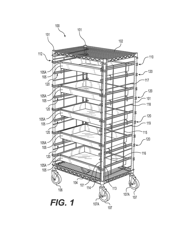
[0012] FIG. 1 is a top perspective view of a tray support system according to
a
first embodiment of the present invention.
[0013] FIG. 2 is a partial isometric view looking upward at the top of the
tray
support system according to the first embodiment of the present invention.
CA 02976407 2017-08-10
WO 2016/130925
PCT/US2016/017767
-6-
100141 FIG. 3A is a top view of the tray support system according to the first
embodiment of the invention.
[0015] FIG. 3B is a front view of the tray support system according to the
first
embodiment of the invention.
[0016] FIG. 3C is a side view of the tray support system according to the
first
embodiment of the invention.
[0017] FIG. 3D is a top perspective view of the tray support system according
to
the first embodiment of the invention.
[0018] FIG. 4A is a bottom view of a rail system or frame for use as one of
the
side rails of the tray support system according to the first embodiment of the
invention.
[0019] FIG. 4B is a top perspective view of a rail system or frame for use as
one
of the side rails of the tray support system according to the first embodiment
of the
invention.
[0020] FIG. 4C is a front view of a rail system or frame for use as one of the
side
rails of the tray support system according to the first embodiment of the
invention.
[0021] FIG. 4D is a side view of a rail system or frame for use as one of the
side
rails of the tray support system according to the first embodiment of the
invention.
[0022] FIG. 5 is a side perspective view of a tray support system according to
a
second embodiment of the present invention.
[0023] FIG. 6A is a bottom view of a rail system or frame for use as one of
the
side rails of the tray support system according to the second embodiment of
the
invention.
CA 02976407 2017-08-10
WO 2016/130925
PCT/US2016/017767
-7-
100241 FIG. 6B is a top perspective view of a rail system or frame for use as
one
of the side rails of the tray support system according to the second
embodiment of
the invention.
[0025] FIG. 6C is a front view of a rail system or frame for use as one of the
side
rails of the tray support system according to the second embodiment of the
invention.
[0026] FIG. 6D is a side view of a rail system or frame for use as one of the
side
rails of the tray support system according to the second embodiment of the
invention.
[0027] FIG. 7 is a front view of the tray support system according to the
second
embodiment of the invention.
[0028] FIG. 8 is a bottom perspective view of a tray support system according
to a
third embodiment of the present invention.
[0029] FIG. 9 is a bottom perspective view of a tray support system according
to
an alternative configuration of the third embodiment of the present invention.
DETAILED DESCRIPTION
[0030] The example embodiments of the invention presented herein are directed
to
an improved tray support system. This is for convenience, and is not intended
to
limit the application of the present invention. In fact, after reading the
following
description, it will be apparent to one skilled in the relevant art how to
implement
the following invention in alternative embodiments, including, for example,
stationary tray support systems and tray support systems with one or more
trays of
various sizes.
CA 02976407 2017-08-10
WO 2016/130925
PCT/US2016/017767
-8-
100311 Figures 1 through 3D show a first embodiment of the present invention.
Specifically, the tray support system, rack, or cart 100 in accordance with
this
embodiment includes four support posts 101. Each post 101 is attached at a top
portion of the respective post 101 to a top surface or shelf 102, and each
post 101
is further attached at a bottom portion of the respective post 101 to a bottom
surface or shelf 104 of the tray support system 100. Each post 101 can
optionally
include a caster or wheel 106, 107 mounted at its bottom. Each caster 106, 107
may swivel about a vertically aligned axis. Moreover, at least one set of the
casters
107 may include a brake 107A that allows for immobilizing the tray support
system or cart 100 in a specific place.
[0032] The tray support system or cart 100 further includes a rail system or
frame
for supporting one or more trays 105. The number of trays is not limited and
can
include one or more trays. Specifically, the frame of the tray support system
100
comprises at least a first pair of parallel rails 110 on a first side of the
tray support
system 100 and at least a second pair of parallel rails 112 on a second side
of the
tray support system 100. The first and second pairs of parallel rails 110, 112
are
configured to support a lip 105A of a tray 105. In particular, the rails of
the first
and second pairs of parallel rails 110, 112 are each spaced apart a specific
distance
to provide a guide space G (see, e.g. Fig. 2) that allows for the lip 105A of
the tray
105 to be guided and aligned between the rails of the first and second pairs
of
parallel rails 110, 112. For example, in one embodiment, a guide space G of
0.090
inches is provided between the rails of the first and second pairs of parallel
rails
110, 112. A guide space G can also be created such that a clearance is
provided
between the upper rail of the each of the first and second pairs of parallel
rails 110,
CA 02976407 2017-08-10
WO 2016/130925
PCT/US2016/017767
-9-
112 and a top edge of the lip 105A of the tray 105. Besides providing a guide
space
G for the lip 105A of the tray 105, the first and second pairs of parallel
rails 110,
112 further provide a motion stop if the tray 105 starts to tip forward. In
particular,
as a tray 105 is pulled forward along the respective first and second pairs of
parallel rails 110, 112, the bottom of the lip 105A of the tray 105 rides
along the
lower rail of the first and second pairs of parallel rails 110, 112, while the
upper
rail of the first and second pairs of parallel rails 110, 112 prevents the
tray from
rotating or flipping forward by engaging with the top of the lip 105A of the
tray
105. In one embodiment, the first and second pairs of parallel rails 110, 112
are
spaced apart a distance to accommodate three-inch sized trays 105 (meaning,
trays
with a height or depth of 3 inches). However, the first and second pairs of
parallel
rails 110, 112 can be configured to accommodate trays of various sizes,
including,
for example, 3 inch, 4.5 inch, and 6 inch sized trays. Moreover, the first and
second pairs of parallel rails 110, 112 are configured to allow for a tray 105
to
easily slide along the first and second pairs of parallel rails 110, 112.
[0033] As also shown in Figs. 1, 2, and 3B-3D, bottom support rails 120 are
provided to support the bottom surfaces of at least the first four trays 105.
Each
bottom support rail 120 is connected to the frame of the tray support system
100
via a connector rail 121 that attaches the bottom support rail 120 to the
frame (see,
e.g., Fig. 2). The bottom support rail 120 extends further inward than either
the
first or second pairs of parallel rails 110, 112 in order to support the
bottom surface
of the tray 105 and to ensure that the bottom support rail 120 will support
the tray
105 if the lip 105A loses engagement with the first and/or second pairs of
parallel
rails 110, 112 (see, e.g., Figs 2 and 4D). Alternatively, a clearance may be
CA 02976407 2017-08-10
WO 2016/130925
PCT/US2016/017767
- 10 -
provided between the bottom surface of the tray 105 and the bottom support
rail
120 to eliminate friction while sliding the tray 105 in a normal operation.
[0034] As shown in Fig. 1, the frame further includes at least a first
vertical rail
113 and a second vertical rail 114 that, when assembled, are disposed adjacent
to
each of the posts 101 of the tray support system 100. Although vertical rails
113,
114 are shown only with respect to one of the posts 101 in Fig. 1, for sake of
simplicity, the same structure is preferably provided for all four posts 101.
The
first and second vertical rails 113, 114 extend from a top portion of a
respective
post 101 to a bottom portion of the respective post 101. The first and second
vertical rails 113, 114 connect to each of the first pairs of parallel rails
110, as well
as each of the bottom support rails 120. In the embodiment of Fig. 1, each of
the
first pairs of parallel rails 110 is shown to wrap around a post 101 on a
first end of
each of the first pairs of parallel rails 110, and to wrap around another post
101 on
a second end of each of the first pairs of parallel rails 110. During
assembly, the
first and second vertical rails 113, 114, as well as each of the first pairs
of parallel
rails 110, which can be preformed as an integral frame, are guided onto the
posts
101 of the system. This allows for ease of assembly because the frame, as
discussed further below, can be initially assembled and thereafter, placed or
slid
onto the posts 101 of the system. Moreover, the frame can be slid right onto
the
posts 101 of the system without requiring further fasteners or attachment
elements.
Accordingly, the first and second vertical rails 113, 114, as well as each of
the first
pairs of parallel rails 110, are configured to effectively guide the frame
onto the
respective posts 101 and thus, to stabilize the frame on the posts 101 of the
tray
support system 100. As noted above, the second side of the tray support system
CA 02976407 2017-08-10
WO 2016/130925
PCT/US2016/017767
-11-
100 can include a second set of vertical rails that are disposed adjacent to
the
respective posts 101 of the second side of the tray support system 100, and
further
connect to each of the second pairs of parallel rails 112 and each of the
bottom
support rails 120 on that side. Moreover, each of the second pairs of parallel
rails
112 is configured to wrap around a post 101 on a first end of each of the
second
pairs of parallel rails 112, and to wrap around another post 101 on a second
end of
each of the second pairs of parallel rails 112.
[0035] The frame of the tray support system 100 of the embodiment of Fig. 1
can
also include at least two stabilizing rails 115, 116 that extend vertically
from a top
portion of the frame to a bottom portion of the frame. In addition, the frame
can
include one or more stabilizing rails 117, 118, 119 that extend horizontally
along
the frame from one post 101 to a second post 101. The stabilizing rails 115-
119
are provided to stabilize and strengthen the frame.
[0036] As shown in the embodiment of Fig. 1, five trays 105 (e.g., three-inch
sized trays) are being supported by the tray support system 100. In
particular, each
tray 105 has a lip 105A that is supported by a first pair of parallel rails
110 on a
first side of the tray support system 100 and a second pair of parallel rails
112 on a
second side of the tray support system 100. While this embodiment depicts five
trays 105 being supported by the tray support system 100, it will be apparent
to one
skilled in the relevant art how to configure a frame to support more or less
trays
105 on the tray support system 100. The trays are generally made of a polymer
or
plastic, such as, for example, fiberglass. However, the material used to make
the
trays is not limited to polymers or plastic.
CA 02976407 2017-08-10
WO 2016/130925
PCT/US2016/017767
- 12 -
[0037] Figs. 3A-3D illustrate various views of the tray support system 100 of
Figs.
1 and 2. Fig. 3A is a top view of the tray support system 100, which depicts
the
top surface or shelf 102 of the tray support system 100 and its attachment to
each
of the posts 101. Fig. 3A further depicts a handle 130 that will be described
in
further detail below. Fig. 3B is a front view of the tray support system 100.
Fig.
3B depicts five trays 105 that are each being supported by the tray support
system
100 via the first and second pairs of parallel rails 110, 112. A bottom
support rail
120 is provided underneath each of the bottom surfaces of each of the first
four
trays 105 on each side of the tray 105 to provide support to the bottom
surfaces of
the first four trays 105. As discussed above, the bottom support rails 120 are
capable of supporting a respective tray 105 in the event that the tray lip
105A loses
engagement with one or both of the first and second pairs of parallel rails
110, 112.
Fig. 3C is a side view of the tray support system 100 that shows a bottom
support
rail 120 supporting each of the first four trays 105. Each of the bottom
support
rails 120 is attached to a respective connector rail 121. As shown in Figs. 3B
and
3C, the fifth or bottom tray 105 is supported by the bottom surface or shelf
104 of
the tray support system 100. Fig. 3D is a top perspective view of the tray
support
system 100. As shown in Fig. 3D, five trays 105 (e.g., three-inch sized trays)
are
being supported by the tray support system 100. In particular, each tray 105
has a
lip 105A that is supported by the first pair of parallel rails 110 on a first
side of the
tray support system 100 and the second pair of parallel rails 112 on a second
side
of the tray support system 100. While this embodiment depicts five trays 105
being supported by the tray support system 100, it will be apparent to one
skilled in
the relevant art how to configure a frame to support more or less trays 105 on
the
CA 02976407 2017-08-10
WO 2016/130925
PCT/US2016/017767
- 13 -
tray support system 100. Fig. 3D also clearly illustrates the handle 130
attached to
the tray support system 100. Each end of the handle 130 is attached to a
respective
post 101 via a clamp (not shown) or other suitable connection. The handle 130
allows for a user to easily maneuver the tray support system 100 or cart when
the
tray support system 100 is being moved using the casters 106, 107.
[0038] Figs. 4A-4D illustrate various views of a rail system or frame used
with the
tray support system 100 of Figs. 1 through 3D. Fig. 4A is a bottom view of the
frame that shows the bottom support rail 120 extending from the connector rail
121. Fig. 4A also shows a lower rail 150, which extends the same distance as
each
of the first and second pairs of parallel rails 110, 112. Thus, as shown in
Fig. 4A,
the bottom support rail 120 extends a greater distance than the lower rail
150, as
well as each of the first and second pairs of parallel rails 110, 112. Figs.
4B, 4C,
and 4D are a top perspective view, a front view, and a side view of the frame,
respectively, that is connected to one side of the tray support system 100.
Figs.
4B-4D illustrate the lower rail 150 of the frame, as well as an upper rail
140. Figs.
4B-4D also show the plurality of first pairs of parallel rails 110 that are
each
configured to align and guide a lip 105A of a tray 105. Figs. 4B-4D also show
the
plurality of bottom support rails 120 that are each configured to support a
bottom
surface of a tray 105. Each of the bottom support rails 120 is attached to a
respective connector rail 121. Each of the first pairs of parallel rails 110
and
connector rails 121 extend from a first vertical rail 160 on one side of the
frame to
a second vertical rail 170 on an opposite side of the frame. In the embodiment
of
Fig. 4B, a second vertical rail 170 and a third vertical rail 180 are provided
on the
same side of the frame for connecting to each of the first pairs of parallel
rails 110
CA 02976407 2017-08-10
WO 2016/130925
PCT/US2016/017767
- 14 -
and the connector rails 121. In the embodiment of Fig. 4C, another vertical
rail
190 is also provided on the same side of the frame as the first vertical rail
160 for
connecting to each of the first pairs of parallel rails 110 and the connector
rails
121. Each of the various rails of the frame of Figs. 4A-4D can be connected to
the
overall frame using, for example, welding. As shown in Figs. 1 and 3D, and as
discussed above, the frame of Figs. 4A-4D is easily assembled and guided onto
the
posts 101 of one side of the tray support system 100 to effectively support
and
guide the trays 105.
[0039] As discussed above, each of the bottom support rails 120 extends a
greater
distance from the respective vertical rail (e.g., 160-190) than the lower rail
150 or
the upper rail 140, as well as each of the first and second pairs of parallel
rails 110,
112. In particular, as shown in Fig. 4D, the upper rail 140, as well as each
of the
first pairs of parallel rails 110 and the lower rail 150, extend a distance Al
from the
third vertical rail 180, while each of the bottom support rails 120 extends a
distance
A2 from the third vertical rail 180. The distance Al is less than the distance
A2
such that the bottom support rails 120 extend a greater distance from the
third
vertical rail 180. By providing bottom support rails 120 that extend a greater
distance than at least the first and second pairs of parallel rails 110, 112,
the bottom
support rails 120 are capable of supporting the bottom surface of the tray
105, even
in the event that the lip 105A of the tray 105 loses engagement with the first
and/or
second pairs of parallel rails 110, 112. As also shown in Fig. 4D, each of the
bottom support rails 120 is positioned a distance B1 from the lower rail of
each of
the first pairs of parallel rails 120, while the lower rail 150 is positioned
a distance
B2 from the lower rail of the lowest first pair of parallel rails 120. These
distances
CA 02976407 2017-08-10
WO 2016/130925
PCT/US2016/017767
- 15 -
B1 and B2 relate to the height of the tray 105 utilized with the tray support
system
100. For example, if 3 inch sized trays 105 are being used with the tray
support
system 100, the distances B1 and B2 must be at around 3 inches to allow for
the
effective placement and alignment of the tray 105 within the guide space G
between the first and/or second pairs of parallel rails 110, and above the
respective
bottom support rail 120 or bottom shelf 104.
[0040] Figs. 5 through 7 show a second embodiment of the present invention.
Specifically, a tray support system or cart 200 in accordance with this
embodiment
includes four support posts 201. Each post 201 is attached at a top portion of
the
respective post 201 to a top surface or shelf 202, and each post 201 is
further
attached at a bottom portion of the respective post 201 to a bottom surface or
shelf
204 of the tray support system 200. Each post 201 also includes a caster or
wheel
206, 207 mounted at its bottom. Each caster 206, 207 may swivel about a
vertically aligned axis. Moreover, at least one set of the casters 206, 207
may
include a brake that allows for immobilizing the tray support system or cart
200 in
a specific place.
[0041] The tray support system or cart 200 further includes a rail system or
frame
for supporting a plurality of trays 205, 205'. Specifically, the frame of the
tray
support system 200 comprises at least a first set of parallel rails 210 on a
first side
of the tray support system 200 and at least a second set of parallel rails 212
on a
second side of the tray support system 200. The first and second sets of
parallel
rails 210 and 212 are configured to support a lip 205A of a tray 205, 205'. In
particular, each of the first and second sets of parallel rails 210, 212
includes at
least four parallel rails that are each spaced apart a specific distance to
provide a
CA 02976407 2017-08-10
WO 2016/130925
PCT/US2016/017767
- 16 -
guide space G (see, e.g., Fig. 2) therebetween that allows for the lip 205A of
the
tray 205, 205' to be guided and aligned between the rails of the first and
second
sets of parallel rails 210, 212. Moreover, by providing a set of parallel
rails (e.g.,
210 and 212), trays 205, 205' of various sizes and configurations, such as,
for
example, 3 inch, 4.5 inch, and 6 inch trays, can be accommodated within the
same
set of parallel rails (e.g., 210 and 212) by placing the lip 205A of the tray
205, 205'
within the appropriate guide space G provided between the various rails of the
first
and second sets of parallel rails 210, 212. For example, in the embodiment of
Fig.
5, the first four upper trays 205 are 3 inch sized trays; thus, the lip 205A
of each of
these trays 205 is aligned and guided within the guide space G provided
between
the lower two rails of each of the first and second sets of parallel rails
210, 212.
However, in the embodiment of Fig. 5, the bottom tray 205' is a 4.5 inch tray;
thus,
the lip 205A of this tray 205' is aligned and guided within the guide space G
provided between the upper two rails of each of the first and second sets of
parallel
rails 210, 212. Besides providing a guide space G for the lip 205A of the tray
205,
205', the first and second sets of parallel rails 210, 212 further provide a
motion
stop if the tray 205, 205' starts to tip forward. Specifically, as discussed
above, as
a tray 205, 205' is pulled forward along the respective first and second sets
of
parallel rails 210, 212, the bottom of the lip 205A of the tray 205, 205'
rides along
a lower rail of the first and second sets of parallel rails 210, 212, while an
upper
rail of the first and second sets of parallel rails 210, 212 prevents the tray
from
rotating or flipping forward by engaging with the top of the lip 205A of the
tray
205, 205'. Moreover, the first and second sets of parallel rails 210, 212 are
CA 02976407 2017-08-10
WO 2016/130925
PCT/US2016/017767
- 17 -
configured to allow for a tray 205, 205' to easily slide along the first and
second
sets of parallel rails 210, 212.
[0042] In the embodiment of Figs. 5 through 7, a plurality of bottom support
rails
220 are also provided to support the bottom surface of each of the trays 205.
Each
of the bottom support rails 220 is connected to the frame of the tray support
system
200 via a connector rail 221 that attaches the respective bottom support rail
220 to
the frame. In addition, as in the embodiment of Fig. 2, each of the bottom
support
rails 220 of Fig. 5 extends further inward than each of the rails of the first
and
second sets of parallel rails 210, 212 in order to support the bottom surface
of the
tray 205 and to ensure that the bottom support rail 220 will support the tray
205 if
the lip 205A loses engagement with either of the sets of parallel rails 210,
212.
Alternatively, a clearance can be provided between the bottom surface of the
tray
205 and the bottom support rail 220 to eliminate friction while sliding the
tray 205
in a normal operation. As shown in Fig. 5, the fifth or bottom tray 205' can
be
supported by the bottom surface or shelf 204 of the tray support system 200.
[0043] As shown in the embodiment of Fig. 5, five trays 205, 205' are being
supported by the tray support system 200. In particular, each tray 205, 205'
has a
lip 205A that is supported by a first set of parallel rails 210 on a first
side of the
tray support system 200 and a second set of parallel rails 212 on a second
side of
the tray support system 200. A bottom support rail 220 is provided underneath
each of the bottom surfaces of each of the first four trays 205 on each side
of the
tray 205 to support the bottom surfaces of the first four trays 205. As
discussed
above, the bottom support rails 220 are also capable of supporting a
respective tray
205 in the event that the tray lip 205A loses engagement with one or both of
the
CA 02976407 2017-08-10
WO 2016/130925
PCT/US2016/017767
- 18 -
first and second sets of parallel rails 210, 212. While this embodiment
depicts five
trays 205, 205' being supported by the tray support system 200, it will be
apparent
to one skilled in the relevant art how to configure a frame to support more or
fewer
trays 205, 205' on the tray support system 200. The trays are generally made
of a
polymer or plastic, such as, for example, fiberglass. However, the material
used to
make the trays is not limited to polymers or plastic. In the embodiment of
Fig. 5,
one of the trays 205, which includes dividers 400 within the tray 205, is
shown in a
forward position after being pulled along the respective rails of the first
and second
sets of parallel rails 210, 212. As shown in Fig. 5, the tray 205 is not
tipping
forward, as can occur in conventional tray support systems, because the tray
205 is
being supported by one or both of the first and second sets of parallel rails
210, 212
and the bottom support rail 220.
[0044] Figs. 6A-6D illustrate various views of a rail system or frame used
with the
tray support system 200 of Fig. 5. Fig. 6A is a bottom view of the frame that
shows the bottom support rail 220 extending from the connector rail 221. Fig.
6A
also shows a lower rail 250, which extends the same distance as each of the
first
and second sets of parallel rails 210, 212. Thus, as shown in Fig. 6A, the
bottom
support rail 220 extends a greater distance than the lower rail 250, as well
as each
of the sets of parallel rails 210, 212. Figs. 6B, 6C, and 6D are a top
perspective
view, a front view, and a side view of the frame, respectively, that is
connected to
one side of the tray support system 200. Figs. 6B-6D illustrate the lower rail
250
of the frame, as well as an upper rail 240. Figs. 6B-6D also show a plurality
of
first sets of parallel rails 210 that are each configured to align and guide a
lip 205A
of a tray 205, 205'. Figs. 6B-6D also show a plurality of bottom support rails
220
CA 02976407 2017-08-10
WO 2016/130925
PCT/US2016/017767
- 19 -
that are each configured to support a bottom surface of a tray 205. Each of
the
bottom support rails 220 are attached to a respective connector rail 221. Each
of
the first sets of parallel rails 210 and connector rails 221 extend from a
first vertical
rail 260 on one side of the frame to a second vertical rail 270 on an opposite
side of
the frame. In the embodiment of Fig. 6B, a second vertical rail 270 and a
third
vertical rail 280 are provided on the same side of the frame for connecting to
each
of the first sets of parallel rails 210 and the connector rails 221. In the
embodiment
of Fig. 6C, another vertical rail 290 is also provided on the same side of the
frame
as the first vertical rail 260 for connecting to each of the first sets of
parallel rails
210 and the connector rails 221. Figs. 6B and 6C also show two stabilizing
rails
300, 310 that extend vertically from a top portion of the frame to a bottom
portion
of the frame. In addition, the frame can include one or more stabilizing rails
320
that extend horizontally along the frame from the first vertical rail 260 to
the
second vertical rail 270. The stabilizing rails 300, 310, 320 are provided to
stabilize and to strengthen the frame. Each of the various rails of the frame
of
Figs. 6A-6D can be connected to the overall frame using, for example, welding.
As shown in, for example, Figs. 5 and 7, the frame of Figs. 6A-6D is easily
assembled and guided onto the posts 201 of one side of the tray support system
200
(as in the first embodiment) to effectively support and guide the trays 205,
205'.
[0045] As discussed above, each of the bottom support rails 220 extends a
greater
distance from the respective vertical rail (e.g., 260-290) than the lower rail
250 or
the upper rail 240, as well as each of the first and second sets of parallel
rails 210,
212. In particular, as shown in Fig. 6D, the upper rail 240, as well as each
of the
first sets of parallel rails 210 and the lower rail 250, extend a distance Al
from the
CA 02976407 2017-08-10
WO 2016/130925
PCT/US2016/017767
- 20 -
third vertical rail 280, while each of the bottom support rails 220 extends a
distance
A2 from the third vertical rail 280. The distance Al is less than the distance
A2
such that the bottom support rails 220 extend a greater distance from the
third
vertical rail 280. By providing bottom support rails 220 that extend a greater
distance than at least the first and second sets of parallel rails 210, 212,
the bottom
support rails 220 are capable of supporting the bottom surface of the tray
205, even
in the event that the lip 205A of the tray 205 loses engagement with the first
and/or
second sets of parallel rails 210, 212. As also shown in Fig. 6D, each of the
bottom support rails 220, as well as the lower rail 250, is positioned a
distance B1
from the fourth or lowest rail of each of the first sets of parallel rails
210. Each of
the bottom support rails 220, as well as the lower rail 250, is also
positioned a
distance B2 from the second rail of each of the first sets of parallel rails
220.
These distances B1 and B2 relate to the height of the trays 205, 205' utilized
with
the tray support system 200. For example, if 3 inch sized trays 205 are being
used
with the tray support system 200, the distance B1 must be around 3 inches to
allow
for effective placement of the tray 205 within the guide space G between the
lower
rails of the first and/or second sets of parallel rails 210, and above the
respective
bottom support rail 220 or bottom shelf 204. Moreover, if 4.5 inch sized trays
205'
are being used with the tray support system 200, the distance B2 must be
around
4.5 inches to allow for effective placement of the tray 205' within the guide
space
G between the upper rails of the first and/or second sets of parallel rails
210, and
above the respective bottom support rail 220 or bottom shelf 204.
[0046] Fig. 7 depicts the second embodiment of a tray support system 200' in
which a plurality of deeper (e.g., 4.5 inch) trays 205' are being supported.
The
CA 02976407 2017-08-10
WO 2016/130925
PCT/US2016/017767
-21 -
same reference numerals are used to depict the same parts that are included
with
this embodiment. As shown in the embodiment of Fig. 7, each of the lips 205A
of
the trays 205' is supported between the upper two rails of the first and
second sets
of parallel rails 210, 212. The first four trays 205' are also supported on
their
bottom surfaces by a respective bottom support rail 220 on each side of the
tray
205', while the fifth or bottom tray 205' is supported by the bottom surface
or shelf
204 of the tray support system 200'. As discussed above, the bottom support
rails
220 are further capable of supporting a respective tray 205' in the event that
the
tray lip 205A loses engagement with one or both of the first and second sets
of
parallel rails 210, 212. The fifth or bottom tray 205' can also be supported
by the
bottom surface or shelf 204 of the tray support system 200' in the event that
this
tray 205' loses engagement with the first and/or second sets of parallel rails
210,
212. While this embodiment depicts five trays 205' of the same size (e.g., 4.5-
inch
trays) being supported by the tray support system 200', it will be apparent to
one
skilled in the relevant art how to position trays 205, 205' of various sizes,
as
discussed above, as well as how to configure a frame to support more or fewer
trays 205' of various sizes on the tray support system 200'.
[0047] Fig. 8 shows a third embodiment of the present invention. Specifically,
Fig. 8 illustrates an alternative configuration for the bottom support rails
520 and
the trays 505. In particular, the bottom support rail 520 includes an offset
525 that
is configured to engage with a tab 560 provided on a raised projection 550
that is
formed on a bottom surface of the tray 505. The offset 525 is created by
including
two inward bends, preferably at 90 degree angles, along an interior edge of
the
bottom support rail 520. The offset 525 of the bottom support rail 520
functions as
CA 02976407 2017-08-10
WO 2016/130925
PCT/US2016/017767
- 22 -
a stop at each end of the offset 525, by engaging with the tab 560 of the
projection
550. Accordingly, the engagement of the tab 560 with the offset 525 prevents
the
tray 505 from being pulled free from the tray support system during a normal
sliding operation. The raised projection 550 is formed linearly along an
insertion
direction of the tray 505. Exterior edges 570 of the projection 550 can be
configured to be guided by guide sections 527 of the bottom support rail 520.
Moreover, the projection 550 and tab 560 are configured to have a height from
the
bottom surface of the tray 505 that allows for the tray 505 to be inserted
into the
tray support system with a slight interference between the tab 560 and the
offset
525, but with a height that is high enough to allow for the offset 525 to act
as a
stopping mechanism when engaging with the tab 560 of the projection 550. For
example, the raised projection 550 and tab 560 have a height from the bottom
surface of the tray 505 such that the tab 560 will engage with the edges of
the
offset 525 when the tray is slid forward on either the front or back side of
the tray
support system. In one embodiment, the height of the raised projection 550 and
tab 560 is preferably 0.25 inches from the bottom surface of the tray 505.
This
engagement of the tab 560 with the offset 525 prevents the tray 505 from being
pulled free from the tray support system during a normal sliding operation,
without
excessive force. However, the raised projection 550 and tab 560 have a height
from the bottom surface of the tray 505, and the bottom support rail 520 is
positioned a specific distance from respective parallel rails (e.g., 110, 112,
210,
212), such that the tray 505 may be inserted or removed by a user into the
tray
support system with a slight interference between the bottom support rail 520
and
the raised projection 550 and tab 560 by slightly raising the tray during the
CA 02976407 2017-08-10
WO 2016/130925
PCT/US2016/017767
- 23 -
insertion or removal from the system. For example, in one embodiment, the
height
of the raised projection 550 and tab 560 is preferably 0.25 inches from the
bottom
surface of the tray 505, while the bottom support rail 520 is positioned a
distance
of at least 3 inches from the respective parallel rails. As discussed above,
the
inclusion of the raised projection 550 and tab 560 on the bottom surface of
the
tray(s) 505, as well as the inclusion of the modified bottom support rail(s)
520 with
an offset 525, allows for the tray(s) 505 to be accessed from either the front
or back
side of the tray support system, while affording the stopping feature
regardless of
which side is chosen. In the embodiment of Fig. 8, the raised projection 550
with
the tab 560 is provided on both sides of the bottom surface of the tray 505.
However, a single projection 550 with a tab 560 may be provided on only one
side
of the bottom surface of the tray 505. In addition, in the embodiment of Fig.
8, the
bottom support rail 520 with offset 525 is included on both sides of the
frame.
However, only one side of the frame may include a bottom support rail 520 with
an
offset 525, while the other side can include the previously disclosed bottom
support rails (e.g., 120, 220).
[0048] Fig. 9 depicts an alternative configuration of the third embodiment of
the
present invention. Specifically, Fig. 9 illustrates another alternative
configuration
for the bottom support rails 620A, 620B and the trays 605. In particular, the
bottom support rail 620A, 620B includes an offset 625A, 625B that is
configured
to engage with a tab 660A, 660B provided on a raised projection 650A, 650B
that
is formed on a bottom surface of the tray 605. The offset 625A, 625B, in this
embodiment, is created by including a single inward bend, preferably at a 90
degree angle, along an interior edge of the bottom support rail 620A, 620B.
The
CA 02976407 2017-08-10
WO 2016/130925
PCT/US2016/017767
- 24 -
offset 625A, 652B of the bottom support rail 620A, 620B functions as a stop by
engaging with the tab 660A, 660B of the projection 650A, 650B. In particular,
as
shown in Fig. 9, a first offset 625A is provided on one side of the interior
edge of a
first bottom support rail 620A, while a second offset 625B is provided on an
opposing side of the interior edge of a second bottom support rail 620B. In
addition, in this embodiment, a first raised projection 650A is provided on
one side
of the tray 605 and includes a first tab 660A that is closer to one end of the
first
projection 650A, while a second projection 650B is provided on an opposing
side
of the tray 605 and includes a second tab 660B that is closer to one end of
the
second projection 650B, such that the first tab 660A is on an end of the first
projection 650A that opposes the end of the second projection 650B on which
the
second tab 660B is provided. During a normal sliding operation, the engagement
of the tab 660A, 660B with the respective offset 625A, 625B prevents the tray
605
from being pulled free from the tray support system, without excessive force.
The
first and second raised projections 650A, 650B are formed linearly along an
insertion direction of the tray 605. Exterior edges 670 of the first and
second
projections 650A, 650B can be configured to be guided by guide sections 627 of
the first and second bottom support rails 620A, 620B. Moreover, the first and
second projections 650A, 650B and the first and second tabs 660A, 660B are
configured to have a height from the bottom surface of the tray 605 that
allows for
the tray 605 to be inserted into the tray support system with a slight
interference
between the tabs 660A, 660B and the respective offsets 625A, 625B, but with a
height that is high enough to allow for the offsets 625A, 625B to act as a
stopping
mechanism when engaging with the tabs 660A, 660B of the projections 650A,
CA 02976407 2017-08-10
WO 2016/130925
PCT/US2016/017767
- 25 -
650B. For example, the raised projections 650A, 650B and tabs 660A, 660B have
a height from the bottom surface of the tray 605 such that the tabs 660A, 660B
will
engage with the edges of the respective offsets 625A, 625B when the tray is
slid
forward on either the front or back side of the tray support system. In one
embodiment, the height of the raised projections 650A, 650B and tabs 660A,
660B
is preferably 0.25 inches from the bottom surface of the tray 605. This
engagement of the tabs 660A, 660B with the respective offsets 625A, 625B
prevents the tray 605 from being pulled free from the tray support system
during a
normal sliding operation, without excessive force. However, the raised
projections
650A, 650B and tabs 660A, 660B, as discussed above, have a height from the
bottom surface of the tray 605, and the bottom support rails 620A, 620B are
positioned a specific distance from respective parallel rails (e.g., 110, 112,
210,
212), such that the tray 605 may be inserted or removed by a user into the
tray
support system with a slight interference between the bottom support rails
620A,
620B and the raised projections 650A, 650B and tabs 660A, 660B by slightly
raising the tray during the insertion or removal from the system. For example,
in
one embodiment, the height of the raised projections 650A, 650B and tabs 660A,
660B is preferably 0.25 inches from the bottom surface of the tray 605, while
the
bottom support rails 620A, 620B are positioned a distance of at least 3 inches
from
the respective parallel rails. As discussed above, the inclusion of the raised
projections 650A, 650B and tabs 660A, 660B on the bottom surface of the
tray(s)
605, as well as the inclusion of the modified bottom support rails 620A, 620B
with
the offsets 625A, 625B, allows for the tray(s) 605 to be accessed from either
the
CA 02976407 2017-08-10
WO 2016/130925
PCT/US2016/017767
- 26 -
front or back side of the tray support system, while affording the stopping
feature
regardless of which side is chosen.
[0049] With the tray support system or cart of the present invention, there
are
notable advantages over other tray support systems or carts known in the art.
The
tray support system or cart of the invention incorporates improved rail
features that
support a plurality of trays while reducing or preventing the tendency of the
trays
to tip and jam. The improved tray support system also preferably prevents the
trays from disengaging with the rails during flexing of the rails of the
system.
[0050] While various example embodiments of the invention have been described
in detail above, it should be understood that they have been presented by way
of
example for purposes of illustration, and not limitation. It is apparent to
persons
skilled in the relevant art(s) that various changes in form and detail can be
made
therein. Modifications may be made to the preferred embodiments of the tray
support system described above without departing from the scope of the present
invention. Thus, the disclosure should not be limited by any of the above
described example embodiments.