Note: Descriptions are shown in the official language in which they were submitted.
CA 02977164 2017-08-18
WO 2016/134461
PCT/CA2016/050174
TRANSITIONING PIPE HANDLER
INVENTOR(S): TODD H. MCCORRISTON, DANIEL M. HUVENAARS, COLIN
E. IRVING, PATRICK D. MCDOUGALL, RONALD GEORGE WILLIAM
POLLARD
OWNER: DRILLFORM TECHNICAL SERVICES LTD.
TECHNICAL FIELD
A pipe handling apparatus is provided. More specifically, a pipe handling
apparatus that may be used as a catwalk in the oil and gas industry is
provided.
BACKGROUND
It is well known that drilling platforms, often referred to as derricks, are
positioned high above the ground to support and rotate long "strings" of pipe.
Depending upon the type of operation, the work floor of the derrick can be
anywhere
from 5 to 30 feet above the ground, requiring that mechanical pipe handlers be
used to
raise and lower very large, heavy sections of pipe between the ground and the
elevated derrick platform. During drilling operations, for example, tubular
casing or
drill pipe "tubulars" are lifted up to the rig floor and threaded together end-
to-end to
form the drill string. This process typically requires the reorientation of
the tubulars
from a horizontal storage position on the ground to a nearly vertical drill
string
position above the rig floor. Similarly, during break-down, each tubular must
be
removed from the platform, and reoriented back to a horizontal position for
storage on
the ground.
It is well known that the frequency of adding tubulars to the existing drills
string is high and can be time consuming. It is also well known that such
processes
can involve manual handling of the piping and, therefore, can be quite
dangerous to
personnel working on or near the drill rig floor. As such, many mechanical
pipe
handlers have been designed to improve the efficiency of the process and to
minimize
the risk of hazardous incidents. For example, some pipe handlers, or
"catwalks", for
transitioning tubulars from the ground level up to the derrick platform are
disclosed in
1
CA 02977164 2017-08-18
WO 2016/134461
PCT/CA2016/050174
United States Patent Nos. 8,764,368, 7,992,646, and United States Patent
Application
Nos. 11/689,279, 12/193,309, and 13/968,424.
There is a need, however, for an adaptable pipe transitioning system that can
easily be used with drilling platforms varying in height. It is desirable that
such a
system be simple and efficient, and utilized in either drilling or servicing
operations.
It is further desirable that such a pipe transitioning system comprise a
unitary
kicker/indexer system.
SUMMARY
The present disclosure relates to an adjustable pipe handler for use in
transitioning pipe, such as tubulars, to elevated platforms varying in height.
Broadly speaking, an adjustable pipe handler for transitioning pipe to an
elevated platform is provided, the pipe handler comprising: a base, having a
front,
middle and rear section, and having a surface forming a track for receiving at
least
one pipe, a lift arm having a first end and a second end, said first end being
pivotally
mounted to the front section of the base and said second end resting against
the
elevated platform, the lift arm being positionable at an incline from the
base, and
forming a channel operably corresponding to the track of the base for
receiving the at
least one pipe therefrom, and a transitioning arm, movably connected to both
the base
and the lift arm, for positioning the lift arm, the transitioning arm also
forming a
channel operably corresponding to the track of the base for receiving at least
one pipe
therefrom and guiding the pipe along the lift arm to the elevated platform.
Broadly speaking, a method of transitioning pipe to an elevated platform is
also provided, the method comprising providing a pipe handling system having a
base
forming a track capable of receiving at least one pipe, a lift arm, pivotally
connected
to the base, for receiving the at least one pipe and guiding same to the
elevated
platform, and a transitioning arm, movably connected to both the base and the
lift arm
for controllably positioning the lift arm at an incline from the base and
configured to
transfer the at least one pipe from the base to the lift arm.
DESCRIPTION OF THE DRAWINGS
2
CA 02977164 2017-08-18
WO 2016/134461
PCT/CA2016/050174
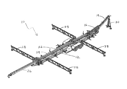
Figure 1 is a perspective view of the present apparatus in an extended or
"open"
position according to embodiments herein;
Figure 2 is a top down view of the present apparatus shown in Figure 1
according to
embodiments herein;
Figure 3 is a side view of the present apparatus shown in Figures 1 and 2
according to
embodiments herein;
Figure 4 is a perspective view of the present apparatus in a retracted or
"closed"
position according to embodiments herein;
Figure 5 is a side view of the present apparatus shown in Figure 4 according
to
embodiments herein;
Figure 6 is a top down view of the present apparatus shown in Figures 4 and 5
according to embodiments herein; and
Figure 7 is a perspective view of the unitary indexer and kicker of the
present
apparatus according to embodiments herein.
DESCRIPTION OF EMBODIMENTS
An adjustable pipe handler or "catwalk" and method of use is provided for
transitioning pipe to and from an elevated platform. It is understood that the
present
apparatus and methodologies may be used in the oil drilling and rigging
industries,
and other appropriate industries to assist with the handling of large, heavy
pipes that
are raised to and lowered from elevated platforms. According to embodiments
herein,
the present apparatus and methodologies provide a mobile transitioning catwalk
capable of transferring at least one piece of large, heavy pipe from a
generally
horizontal storage position at or near the ground level to a near-vertical
position above
elevated platforms varying in height. The present system will now be described
having regard to Figs. 1 ¨ 7.
Having regard to Figs. 1 and 2, the present transitioning catwalk 10 generally
comprises a base 12, a lift arm 14 and a transitioning arm 16. Catwalk 10 may
be
configured to be mobile (e.g. towed behind a vehicle) and conveniently
transported
between different elevated platforms, and can comprise anchoring means for
securing
base 12 (e.g. to uneven surfaces) during use. As will become apparent, it is
an aspect
of the present catwalk 10 that it may be utilized at elevated platforms
varying in
3
CA 02977164 2017-08-18
WO 2016/134461
PCT/CA2016/050174
height (not shown). In embodiments herein, the elevated platform may be at
least five
feet from the ground. In other embodiments, the elevated platform may be
between
approximately five and thirty feet from the ground. It is understood that the
present
transitioning catwalk may be automatically controlled, such that operating
personnel
may control the system remotely.
Having regard Fig. 3, base 12 can comprise front, middle and rear sections.
Without limitation, reference to the "front" section of the base 12 denotes
the section
of the base 12 closest to the elevated platform (not shown). Such reference to
"front",
"middle" and "rear" sections is made for explanatory purposes only and in no
way is
intended to limit the present apparatus and methodologies. Base 12 can further
comprise a "U" or "V" shaped surface 22 forming a channel or "track" 24 for
receiving at least one pipe element, such as a tubular pipe element. Track 24
may be
arranged so as to generally extend the length of the surface 22 of the present
pipe
handler 10. Preferably, base 12 is configured without a platform or deck,
enabling
personnel to reach pipe in the track 24 (if necessary) from the ground and
preventing
personnel from mounting the base 12.
In one embodiment, base 12 may comprise at least one extension arm 26,
operative to extend the surface 22 of the base 12. Without limitation, the at
least one
extension arm 26 may be utilized where it is desirable to connect more than
standard
pipe element end-to-end within the track 24 to make a longer pipe (e.g. where
two
range 2 tubulars are threaded together), or where longer tubulars (e.g. range
3, 45ft
pipe) are being transitioned to/from the platform.
The at least one extension arm 26 may be positioned at or near the rear end of
the base 12. In one embodiment, extension arm 26 may comprise a folding
section
rotatable about a pivot joint connected to the base 12, such that extension
arm 26 may
swing out horizontally outwardly from a first "closed" position (e.g. stowed
or nested
against the side of the base 12) to a second "open" position co-axially
aligned with
longitudinal axis of the base 12. In another embodiment, extension arm 26 may
comprise two diametrically opposed folding half-sections positioned on each
side of
the base 12, such that each half section is rotatably mounted to the base 12
at a pivot
joint and swings horizontally outwardly away from the base 12 (and in opposite
directions from each other) until they connect together to form one unitary
extension
4
CA 02977164 2017-08-18
WO 2016/134461
PCT/CA2016/050174
arm 26 aligned with base 12. It is an aspect of the present apparatus and
methodologies that the at least one extension arm 26 be configured so as to
provide a
small base 12 for easy transport. One or more extension arms 26 may comprise
anchoring means as known in the industry for securing the extension arm 26
during
use.
In one embodiment, base 12 may further comprise at least two diametrically
opposed pipe supply racks 28. Supply racks 28 may contain a supply of pipes
positioned in parallel alignment with the base 12 and track 24. It is
understood that
pipes can be arranged on supply racks 28 to enable alignment of opposite male
and
female pipe threading elements. In other words, pipes can be arranged so that
all of
the respective male, or as-called "pin" ends, and female ends are positioned
in the
same orientation.
The opposed pipe supply racks 28 may be positioned at or near the middle
section of the base 12. In one embodiment, opposed pipe supply racks 28 are
positioned to allow pipes to roll from the rack onto the surface 22 of the
base 12 and
into the track 24. As would be understood, the height of the pipe supply racks
28 may
adjustable (e.g. using hydraulics) so as to raise and/or lower the racks
relative to the
height of the base 12. Adjusting the height of the pipe racks 28 may be
automatically
or manually controlled. In one embodiment, each diametrically opposed pipe
rack 28
may comprise independently operated hydraulic lifts for raising/lowering the
racks
28. It is contemplated that the present pipe handler 10 may comprise at least
2
diametrically opposed racks 28. In some embodiments, the present pipe handler
10
may comprise at least 4 or 6 diametrically opposed pipe racks 28, as
determined by
the length of pipe being used. Once positioned in the track 24, a skate may be
used to
raise the pipe to the elevated platform.
As above, the present pipe handler 10 further comprises a lift arm 14 having a
first end and a second end. Having regard to Figs. 4 ¨ 6, the first end of
lift arm 14
may pivotally mounted to the front section of the base 12, enabling the lift
arm 14 to
rotate from a "closed", nested positioned against the surface 22 of the base
12
upwardly and away from the base 12 to an "open" position where the second free
end
of the lift arm 14 rests against and cooperates with the elevated platform
floor (not
shown). Lift arm 14 may comprise a top surface forming a channel operably
5
CA 02977164 2017-08-18
WO 2016/134461
PCT/CA2016/050174
corresponding with track 24 of the base 12. In some embodiments, lift arm 14
may be
extendable so as to reach the platform. For example, lift arm 14 may comprise
at least
one telescoping element enabling the second, "leading" end of the arm 14 to
advance
upwardly towards the platform floor. Extension of lift arm 14 may be driven by
at
least one hydraulic cylinder, such that the relative position of the
telescoping elements
may be locked at any desired position. Typically, the lift arm 14 is
extendable up to
heights desired in the industry, or as high as approximately 45 feet. It is
understood
that each telescoping element further comprises a surface forming a channel
operably
corresponding with track 24 of the base 12. Optionally, lift arm 14 may
further
comprise stabilizing arms 30 for supporting the lift arm 14 when in the
raised,
extended position.
As above, the present pipe handler 10 further comprises a transitioning arm 16
for controllably adjusting the pivotable transition of the lift arm 14 from
the base 12
(i.e. from the closed to the open position). Transitioning arm 16 may comprise
a first
end and a second, wherein the first end may be connected to the base 12 and
the
second end may be connected to the lift arm 14. Transitioning arm 16 may be
operative to controllably adjust the height of the lift arm 14, that is ¨ to
increase or
decrease the incline of the lift arm 14 from base 12, enabling lift arm 14 to
reach
platforms of varying heights. As would be understood, transitioning arm 16 may
be
automatically controlled (i.e. via one or more hydraulic cylinders).
In one embodiment, the transitioning arm 16 is movably connected to both
base 12 and lift arm 14. For example, in one embodiment, first end of
transitioning
arm 16 may be slidably connected to base 12, while second end of transitioning
arm
16 may be pivotally connected to lift arm 14. It is understood that any
movable
connection of the transition arm 16 operative to enable controllable
transition of the
lift arm 14 from the base 12 is contemplated. It is further understood that
transitioning
arm 16 may further have a surface forming a channel operably corresponding
with
track 24 of the base 12 and lift arm 14, enabling smooth and uninterrupted
guidance
of a pipe element from the base 12 along the lift arm 14 and ultimately to the
elevated
platform, or in reverse from the lift arm 14 back to the base 12.
Having specific regard to Fig. 5, first end of transitioning arm 16 may be
slidably connected to base 12 via a roller and track system 32, or any other
such
6
CA 02977164 2017-08-18
WO 2016/134461
PCT/CA2016/050174
means for enabling smooth movement of the first end of the transitioning arm
16
back-and-forth along the surface 22 of the base 12. Second end of
transitioning arm
16 may be rotatably connected to lift arm 14 by pivot 34, or any other such
means as
to enable smooth movement of the second end of the transitioning arm 16 and
the lift
arm 14. It would be understood that the location of the pivot 34 is determined
for
optimum movement of the lift arm 14. It is an aspect of the present apparatus
that the
lift arm 14 may extend at any desired angle from the base 12 to reach the
elevated
platform. Without limitation, as shown in Fig. 3, in some embodiments, it is
contemplated that the lift arm 14 may extend from the base 12 at an angle of
approximately 1550 (or approximately 25 from the horizontal plane of the
ground).
In other embodiments, it is contemplated that the lift arm 14 may extend from
the
base 12 at an angle of approximately 40 from the base 12 (or approximately 50
from
the horizontal plane of the ground).
Having regard to Fig. 7, the present pipe handler 10 may further comprise a
modified indexer and kicker elements 40. As is understood, an indexer is
provided in
conventional pipe handlers to move the pipe elements into the track 24
smoothly from
the pipe supply racks 28, while kickers are provided to "kick" the pipe out of
the track
24 for placement back on the supply racks 28 for storage.
According to embodiments herein, the base 12 of the present pipe handler 10
may be configured with at least one gap within which are provided combined
indexer/kicker 40 for loading and unloading pipe. Each indexer/kicker 40 may
be
configured to provide mirrored indexing elements 42 and kicking elements 44
(i.e. on
opposite sides of track 24), such that pipes within the indexer/kicker 40 can
be
smoothly transitioned into or out of track 24 in either direction, that is ¨
to pipe racks
28 on either side of the pipe handler 10. Indexer/kicker 40 can comprise a
frame
enabling each indexer/kicker 40 to be removably attached to the pipe handler
10 for
easy handling by those skilled in the art.
Although a few embodiments have been shown and described, it will be
appreciated by those skilled in the art that various changes and modifications
can be
made to these embodiments without changing or departing from their scope,
intent or
functionality. The terms and expressions used in the preceding specification
have
been used herein as terms of description and not of limitation, and there is
no
7
CA 02977164 2017-08-18
WO 2016/134461
PCT/CA2016/050174
intention in the use of such terms and expressions of excluding equivalents of
the
features shown and described or portions thereof, it being recognized that the
invention is defined and limited only by the claims that follow.
8