Note: Descriptions are shown in the official language in which they were submitted.
CA 02978247 2017-08-30
Method and apparatus for manufacturing a profile element
FIELD OF THE INVENTION
The present invention relates to a method for manufacturing a profile element
for
sealing building-structure joints, especially for sealing against sound and
smoke and
optionally against fire, to an apparatus for manufacturing such a profile
element and to
the use of the profile element manufactured according to the invention for the
acoustic,
smokeproof and/or fireproof sealing of connecting joints in drywalls,
especially of
expansion joints. In particular, the invention relates to an improved method
.for
continuous and endless manufacture of such a profile element.
BACKGROUND OF THE INVENTION
Connecting joints are usually formed when different building parts meet.
Connecting
joints are found in the region of connection to the inter-story ceiling, to
the floor and to
massive walls. Due to weight loading or thermal influences, the ceiling in
buildings may
be forced upward or downward. To prevent damage to the drywall, the upper
connecting joint in this case is made as an expansion joint. Thus joints for
creating
discontinuities in building parts in order to prevent stress cracking are
known as
expansion joints. The ceiling profile is made in such a way that a relative
movement
between ceiling profile and the vertical wall components is possible.
In general, a channel profile constituting part of the studwork is fastened to
the
connecting building parts. The gypsum boards themselves are attached at a well-
,
CA 02978247 2017-08-30
- 2 -
defined spacing to the connecting building part. Usually sealing of the system
is
provided in the gap between gypsum board and ceiling. For this purpose, either
a
suitable sealing compound is introduced, processed with joint spray, or else
the gap is
provided with a joint cord or filled with mineral wool and provided at the
surface with a
sealing layer. In these cases, the material present in the joint presents
relatively strong
resistance to movement, with the consequence that comparatively large joint
widths
are necessary in order to achieve adequate movement absorption.
Different methods for manufacturing profile elements, such as profile strands
and joint
cords, for sealing of building-structure joints, especially connecting joints,
against
smoke and fire are known from the prior art.
DE 3038524 Al describes an expansion-joint tape, which is provided with a
flexible
tube, wherein the expansion-joint tape is introduced into a joint between the
concrete
elements. The flexible tube is used to fill subsequently with further joint
material, such
as polyurethane, in order to seal the joint at a later time, but this makes
mounting and
handling difficult.
DE 4006997 Al describes a method and an apparatus for manufacturing profile
strands of fire-protection foam materials using a reaction mixture that is
prepared in a
mixer then filled into a closed, flexible and airtight film tube, wherein the
film tube is
removed before use of the profile strand.
DE 102010008570 Al describes a method for manufacturing a fire-protection
joint
cord, wherein an intumescent foam flows into a tube and is foamed. A
disadvantage in
DE 102010008570 Al is the predetermined diameter of the tube as well as
backing-up
of the material compound that may occur during the manufacturing process or is
insufficient material compound in the manufactured joint cord.
The prior art systems exhibit further additional disadvantages, such as, for
example,
considerable time consumption during manufacture due to complex steps of
cleaning of
the system or due to tedious setting-up, high costs, buildup of the joint cord
or of the
3
profile element comprising several components or complex construction
elements, poor
cuttability, high weight or very inconvenient mounting for building-structure
joints,
especially for connecting joints.
It would therefore be very useful and/advantageous to provide a method for
manufacturing a profile element for sealing building-structure joints,
especially for sealing
against sound and smoke and optionally against fire, which method avoids the
disadvantages of the known methods. In particular, the object of the present
invention is
to provide an improved method for continuous and endless manufacture of such a
profile
element.
It would therefore be very useful and/advantageous to provide an apparatus
that permits
cost-effective, economic, continuous and endless manufacture of a profile
element.
It would therefore be very useful and/advantageous to provide the use of the
profile
element manufactured according to the invention for acoustic, smokeproof
and/or
fireproof sealing of connecting joints in drywalls, especially of expansion
joints.
SUMMARY OF THE INVENTION
According to one aspect of the present invention, an object is to provide a
method for
manufacturing a profile element for sealing a building-structure joint,
comprising the
following steps:
a) providing a film,
b) applying a free-flowing reaction mixture on an upper side of the film,
c) joining a first side-edge region of the film with a second side-edge region
of the
film to create a profile element of a first shape,
d) forming the free-flowing reaction mixture, and
e) shaping the profile element to a second shape different from the first
shape by
applying pressure to the film using at least one profile corresponding to the
second
shape, wherein
the volume of the free-flowing reaction mixture to be applied is dosed such
that, in
the fully reacted state, the volume corresponds to an inside volume of the
profile element,
and wherein the film completely encloses the reaction mixture, and wherein the
Date Recut/Date Received 2023-03-16
3a
at least one profile applies the pressure to simultaneously form at least a
first region and
a second region of the profile element, the first and second regions having
respective
first and second shapes and joined to have a continuous one-piece construction
formed
from the foamed reaction mixture.
According to another aspect of the present invention, an object is to provide
an apparatus
for manufacturing a profile element for sealing a building-structure joint,
with a casting
system for mixing and applying a free-flowing reaction mixture, characterized
by:
a) a feed apparatus for feeding a film,
b) a roll for perforating the film,
c) at least one conveying means for laying the film flat and conveying it,
d) a forming shoulder to apply pressure to the film for shaping the profile
element,
e) a thermal welding system for joining a first side-edge region of the film
with a
second side-edge region of the film to form a profile element of a first
shape,
f) a reaction section for foaming the free-flowing reaction mixture,
g) at least one profile to shape the profile element to a second shape
different from
the first shape, and
h) a cutting unit for cutting the profile element to the desired length,
wherein the at
least one profile has a shape which simultaneously applies pressure to the
film of the
profile element to form at least a first region and a second region of the
profile element,
the first and second regions having respective first and second shapes and
joined to
have a continuous one-piece construction formed from the foamed reaction
mixture.
Other possible aspect(s), object(s), embodiment(s), variant(s) and/or
advantage(s) of the
present invention, all being preferred and/or optional, are briefly summarized
hereinbelow.
For example, according to one possible emblement, the present invention
relates to a
method for manufacturing a profile element for sealing a building-structure
joint,
comprising the following steps:
a) providing a film,
b) applying a free-flowing reaction mixture on an upper side of the film,
C) joining a first side-edge region of the film with a second side-edge region
of the film
to create a substantially cylindrical profile element, wherein
Date Recut/Date Received 2023-03-16
CA 02978247 2017-08-30
- 4 -
the volume of the free-flowing reaction mixture to be applied is dosed such
that it
corresponds to the inside volume of the manufactured profile element, and
wherein the
film completely encloses the reaction mixture.
The present invention further relates to an apparatus for manufacturing a
profile
element for sealing a building-structure joint, with a casting system for
mixing and
applying a free-flowing reaction mixture, characterized by
a) a feed apparatus for feeding the film,
b) a roll for perforating the film,
c) at least one conveying means for laying the film flat and conveying it,
d) a forming shoulder for shaping the profile element,
e) a thermal welding system for joining a first side-edge region of the film
with a
second side-edge region of the film,
f) a reaction section for foaming the free-flowing reaction mixture,
g) conveying equipment for exactly guiding the film,
I,) a cutting unit for cutting the profile element to the desired length, and
i) optionally at least one metal profile for shaping the profile to the
desired geometry.
The present invention further relates to the use of the profile element
manufactured
according to the invention for acoustic, smokeproof and/or fireproof sealing
of
connecting joints in drywalls, especially of expansion joints.
Some other objects and features of this invention are obvious and some will be
explained hereinafter. In particular, the subject matter of the present
invention will be
described in detail by reference to the following figures:
BRIEF DESCRIPTION OF THE FIGURES
Fig. 1 shows a sketched embodiment of the inventive apparatus for
manufacturing a
profile element.
CA 02978247 2017-08-30
,
- 5 -
Fig. 2a shows a sketched front view of an embodiment of a profile element
manufactured according to the invention.
Fig. 2b shows a cross section through an embodiment of a profile element
manufactured according to the invention.
Fig. 2 shows a perspective view of an embodiment of a profile element
manufactured
according to the invention.
Figure 3 shows the application of an embodiment of a profile element
manufactured
according to the invention for acoustic, smokeproof and/or fireproof sealing
of
connecting joints in drywalls.
DETAILED DESCRIPTION OF THE INVENTION
The following terms are used within the scope of the present invention:
Within the scope of the present invention, the term "profile geometry"
comprises
various cross-section types of the profile element. This means that
particularly the
sealing regions of the profile element may have different cross-section types.
Cross-
section types are understood among other possibilities as round profile (round
cross
section), polygonal profile (polygonal cross section), especially square
profile (square
cross section), rectangular profile (rectangular cross section), parallelogram
profile
(cross section in the shape of a parallelogram), triangular profile
(triangular cross
section), etc.
Within the scope of the present invention, the term "deformable" means that
irregularities in the building part, against which the profile element is
pressed, can be
evened out. In this connection, "plastically deformable" means that the
profile element
is deformable and no longer returns to its original shape after deformation.
Analogously, "elastically deformable" means that the profile element is
deformable and
returns to its original shape after deformation, i.e. the material can be
deformed
reversibly to a certain extent.
CA 02978247 2017-08-30
,
- 6 -
The terms "exhibit", "with" and "have" are intended to be inclusive and mean
that
elements other than those cited may also be meant.
Within the scope of the present invention, the term "intumescence" means that,
under
the effect of heat, for example in the event of a fire, the material swells
and forms an
insulating layer of flame-retardant material, i.e. intumesces.
Within the scope of the present invention, "slow-burning foam" is understood
as a foam
that offers no possibility of fire propagation due to the foam, is not
spontaneously
flammable and also does not drip.
As used within the scope of the present invention, the singular forms "one",
"a" and
"an" also include the corresponding plural forms, unless something different
can be
inferred unambiguously from the relationship. Thus, for example, the term
"one" is
intended to mean "one or more" or "at least one", unless otherwise indicated.
In one aspect, the present invention relates to a method for manufacturing a
profile
element for sealing a building-structure joint, comprising the following
steps:
a) providing a film,
b) applying a free-flowing reaction mixture on an upper side
of the film,
C) joining a first side-edge region of the film with a second side-edge region
of the film
to create a substantially cylindrical profile element, wherein
the volume of the free-flowing reaction mixture to be applied is dosed such
that it
corresponds to the inside volume of the manufactured profile element, and
wherein the
film completely encloses the reaction mixture.
In a further aspect, the present invention relates to an apparatus for
manufacturing a
profile element for sealing a building-structure joint, with a casting system
for mixing
and applying a free-flowing reaction mixture, characterized by
a) a feed apparatus for feeding the film,
b) a roll for perforating the film,
c) at least one conveying means for laying the film flat and conveying it,
CA 02978247 2017-08-30
- 7 -
d) a forming shoulder for shaping the profile element,
e) a thermal welding system for joining a first side-edge region of the film
with a
second side-edge region of the film,
f) a reaction section for foaming the free-flowing reaction mixture,
g) conveying equipment for exactly guiding the film,
h) a cutting unit for cutting the profile element to the desired length, and
i) optionally at least one metal profile for shaping the profile to the
desired geometry.
In yet a further aspect, the present invention relates to the use of the
profile element
manufactured according to the invention for acoustic, smokeproof and/or
fireproof
sealing of connecting joints in drywalls, especially of expansion joints.
It has been discovered that the inventive method is particularly suitable for
manufacturing a profile element in simple, continuous, economic and cost-
effective
manner, for safely sealing a building-structure joint between two adjacent
building
parts, especially against sound and/or smoke and optionally also against fire.
Therefore it is an objective of the present invention to describe the method
for
manufacturing a profile element for sealing a building-structure joint.
Furthermore, it is
an objective of the present invention to describe in detail the apparatus for
manufacturing a profile element for sealing a building-structure joint.
Furthermore, it is
an objective of the present invention to describe the use of the profile
element
manufactured according to the invention for acoustic, smokeproof and/or
fireproof
sealing of connecting joints in drywalls, especially of expansion joints.
Such a profile element can be manufactured according to the invention by
applying a
suitable free-flowing reaction mixture on a flat film, then joining a first
side-edge region
thereof with a second side-edge region to create a substantially cylindrical
profile
CA 02978247 2017-08-30
,
- 8 -
element, wherein the foaming, deformable material then passes together with
the film
through a reaction section and is formed to a profile element.
Therefore the inventive method for manufacturing a profile element for sealing
a
building-structure joint comprises the following steps:
a) providing a film,
b) applying a free-flowing reaction mixture on an upper side of the film,
c) joining a first side-edge region of the film with a second side-edge
region of the film
to create a substantially cylindrical profile element, wherein
the volume of the free-flowing reaction mixture to be applied is dosed such
that, in the
fully reacted state, it corresponds to the inside volume of the manufactured
profile
element, and wherein the film completely encloses the reaction mixture.
Furthermore, the inventive method comprises the following steps:
d) foaming the free-flowing reaction mixture,
e) optionally shaping the profile to the desired geometry, and
f) cutting the profile element to the desired length.
According to the invention, what takes place in the first step of the method
is the
provision of a film by means of a feed apparatus, which comprises at least one
roll,
over which the film is fed from a film supply to a rotating roll for
perforation.
Expediently, the provided films consist of plastic. The material of the film
is preferably a
plastic material, which does not form any adhesive bonds with the foam system
and
withstands the foaming pressures without additional bracing mold.
Alternatively, if other
films are used, for example of paper or fabric, the foaming in the film sheath
may also
take place in a bracing mold, which defines the outer contour of the film as
it expands
during the foaming process.
In the inventive method, the film is preferably provided as a perforated film.
Suitable
film materials, among others, are polymers, such as, for example, silicone,
polyethylene, polypropylene, polyurethane, polyvinyl chloride, rubber and/or
mixtures
CA 02978247 2017-08-30
- 9 -
thereof. Preferably the film is provided as a polyethylene film. In a
particularly preferred
embodiment of the film, the film is a perforated polyethylene film.
Perforation of the film can be achieved by means of a rotating roll or other
means
suitable for generating a perforation. Preferably the perforation of the film
takes place
by means of a rotating roll with attached needles. Alternatively, the
perforation may
also be generated by slit and hole punches. The perforation permits ambient
air
trapped in the film tube as well as reaction gases evolved during the foaming
reaction
of the free-flowing reaction mixture to escape and thus prevents gas
inclusions, which
may cause bubble formation inside the profile element or under the film.
Because of
the perforation and thus the ability of the gas to escape, uniform shaping is
assured.
In a subsequent step of the inventive method, the film is laid flat on a
conveying
means, preferably a conveyor belt or treadmill, and passed over a forming
shoulder,
where the side-edge regions of the film are turned up slightly in order that
the free-
flowing reaction mixture can be applied in a subsequent step.
According to the invention, a deformable free-flowing reaction mixture is used
in the
method. This material may be either plastically or elastically deformable.
Preferably the
.. deformable free-flowing reaction mixture is a polyethylene, a polyurethane
or a cellular-
rubber mixture. In particular, the profile element in finished condition
consists of a
material that is resilient after compression, such as foam, sponge rubber,
cellular
rubber or the like. Common foams such as polyethylene and polyurethane foams
or
cellular rubber can be mentioned as foam material. This foam may be an open-
celled
.. foam with very low air passage resistance, or else an approximately closed-
celled foam
with extremely low air permeability values. Even foams with air permeability
values
lying between the two extreme cases mentioned in the foregoing may be used
within
the scope of the present invention. Preferably, the free-flowing reaction
mixture is a
polyurethane mixture.
CA 02978247 2017-08-30
,
- 10 -
It has proved advantageous when the profile element manufactured according to
the
inventive method consists of a slow-burning foam, such a cellular rubber or
polyurethane foam, for example, which is jacketed with a film. In the case of
a slow-
burning foam, there is no possibility that fire will be propagated by the
foam.
Spontaneous inflammation is ruled out by the above-mentioned foam-type
starting
materials. It is also advantageous that no dripping occurs in the event of
fire. A slow-
burning foam should still have at least 20%, still at least 25%, preferably
still at least
30%, between 20% and 60%, between 20% and 40%, preferably between 25% and
30% of its initial volume in a temperature range between 500 C and 800 C.
Furthermore, a slow-burning foam should still have at least 10%, at least 20%,
preferably still at least 30%, between 10% and 40%, between 10% and 30%,
preferably
between 15% and 20% of its initial mass in a temperature range between 500 C
and
800 C.
Furthermore, the deformable free-flowing reaction mixture may contain
appropriate
additives if fire protection properties such as intumescence, for example, are
desired.
Under the effect of heat, such as in the event of fire, the material swells
and forms an
insulating layer of flame-retardant material. The formation of a voluminous
insulating
layer, namely an ash layer, may take place due to the chemical reaction of a
mixture of
compounds that are appropriately matched to one another and that react with
one
another under the effect of heat. Such systems are known to the person skilled
in the
art as chemical intumescence, and they may be used according to the invention.
Alternatively, the voluminous insulating layer may be formed by swelling of an
individual compound, which releases gases under the effect of heat, even
though no
chemical reaction has occurred between two compounds. Such systems are known
to
the person skilled in the art as physical intumescence, and they may also be
used
according to the invention. According to the invention, the two systems may be
used
respectively alone or together as a combination.
In a preferred embodiment of the method of the present invention, the free-
flowing
reaction mixture is an intumescent polyurethane mixture.
CA 02978247 2017-08-30
,
- 1 1 -
As an example, the free-flowing reaction mixture may be mixed in an upstream
mixing
process, e.g. already in a system suitable for application of the free-flowing
reaction
mixture, such as a casting system.
According to the invention, the application of the free-flowing reaction
mixture takes
place by uniform orthogonal dosing on an upper side of the film. In
particular, it is
necessary, for inventive manufacture of the profile element, that the free-
flowing
reaction mixture be dosed in uniformly orthogonal manner on the upper side of
the
open, flat film. Thereby the backing-up of the material compound that may
occur in an
already prefabricated tube during the manufacturing process, or insufficient
material
compound in the manufactured joint cord, is prevented. Preferably, the volume
of the
free-flowing reaction mixture to be applied is dosed such that in the fully
reacted state it
corresponds to the inside volume of the manufactured profile element.
The filled film is then passed by means of conveying equipment to a welding
system,
where a first side-edge region of the film is joined with a second side-edge
region of the
film to create a substantially cylindrical profile element. Preferably, the
step of joining
by thermal welding takes place with formation of a fish-fin weld seam. In the
process,
the film should completely enclose the reaction mixture.
The tubular profile element formed in this way is then passed by means of
conveying
equipment over a reaction section, in which foaming of the free-flowing
reaction mixture
takes place, Preferably, the foaming of the free-flowing reaction mixture
takes place
within a time interval of 15 to 90 seconds. The foaming takes place between
the
thermal welding system and a cutting unit. In a particular embodiment of the
method of
the present invention, the conveying equipment comprises a conveyor belt or
treadmill
with guide elements, e.g. knobs or dimples, for exactly guiding the film.
During passage over the reaction section, shaping to the desired profile
geometry may
optionally take place. Preferably, the desired profile geometry can be formed
by at least
CA 02978247 2017-08-30
- 12 -
one metal profile. Thereupon the finished profile element is passed to a
cutting unit,
where cutting of the profile element to the desired length takes place.
In this way the inventive method permits cost-effective, economic, continuous
and
endless manufacture of profile elements. The inventive method is preferably
carried out
by means of an apparatus for manufacturing such profile elements.
Such an apparatus for manufacturing such profile elements is provided with a
casting
system for mixing and applying a free-flowing reaction mixture and is
characterized by
a) a feed apparatus for feeding a film,
b) a roll for perforating the film,
C) at least one conveying means for laying the film flat and conveying it,
d) a forming shoulder for shaping the profile element,
e) a thermal welding system for joining a first side-edge region of the film
with a
second side-edge region of the film,
f) a reaction section for foaming the free-flowing reaction mixture,
g) conveying equipment for exactly guiding the film,
h) a cutting unit for cutting the profile element to the desired length, and
i) optionally at least one metal profile for shaping the profile to the
desired geometry.
Preferably, the feed apparatus for feeding the film comprises at least one
roll. Further
preferably, the conveying equipment for exactly guiding the film comprises a
conveyor
belt or treadmill with guide elements, e.g. knobs or dimples. Preferably, the
metal
profile for shaping the desired profile geometry may be provided with any
desired
shape, and thus the profile geometry of the profile element can be
predetermined.
Particular practical importance is attached to one special configuration of
the profile
element manufactured according to the invention for sealing a joint between a
first
building part and a second building part, wherein the profile element
comprises an
elongated connecting element and at least two sealing regions, which are
positioned
CA 02978247 2017-08-30
- 13 -
on the connecting element, along the outer periphery, spaced apart, side-by-
side and
running in the longitudinal direction of the connecting element. Preferably,
the profile
element manufactured according to the invention is used for acoustic,
smokeproof
and/or fireproof sealing of connecting joints in drywalls. In this connection,
it is
particularly preferred that the profile element be positioned in the upper
region of the
connecting joint and be configured to seal the joint from the outside.
Preferred cross-section shapes of the sealing regions of the profile element
manufactured according to the invention are round profile and polygonal
profile,
especially rectangular profile, square profile, parallelogram profile and
triangular profile.
Round profile is particularly preferred. Nevertheless, other or mixed profile
geometries
are also conceivable and possible, as long as the sealing regions adjoin both
building
parts after installation of the profile element and are able to seal the joint
that is present
between the building parts.
The dimension and profile geometry as well as the materials of the profile
element
manufactured according to the invention are chosen to correspond to the
planned use
of the profile element.
In general, the dimension of the profile element manufactured according to the
invention is chosen as a function of the profiles being used and of the
material being
used. The dimension must be chosen such that the profile element fills the gap
between the gypsum board and the ceiling and bears sealingly both on the
ceiling and
on the gypsum board. If a vertical movement of the gypsum boards is to be
permitted,
the profile element, especially the sealing regions, must follow the movement
of the
gypsum board, so that the contact with the gypsum board is not torn apart and
no
spaces are able to form between sealing region and gypsum board. For this
purpose,
the profile element manufactured according to the invention consists of
resilient and
compressible material, such as polyurethane foam, and is appropriately
precompressed during mounting of the gypsum board, so that a downward movement
of the gypsum board, whereby the gap between this and the ceiling becomes
larger,
can be followed. In this way, the preadjusted freedom of movement of the
gypsum
board determines the dimension of the profile element.
=
CA 02978247 2017-08-30
,
- 14 -
The region of the connecting element disposed between the two sealing regions
defines a support region, which consists only of the connecting element. This
support
region is dimensioned such that it corresponds at least to the width of the
web of the
channel profile. Hereby the installation and especially the positioning of the
profile
element on the web of the channel profile are facilitated.
The positioning of the profile element on a building part may be achieved in
one step. It
is also possible that the profile element in turn has means for fastening to a
building
part, such as a drywall profile, for example in the form of a self-adhesive
layer, in the
form of interlocking or frictionally acting means, such as suitable profiled
shapes or the
like. The profile element manufactured according to the invention is
preferably
positioned on a building part in one step.
The use of a profile element manufactured according to the invention
comprises,
before attachment of a first building part, positioning on the first building
part, and then
fastening together therewith on a second building part in the usual way, e.g.
by screws
or nails. Preferably the first building part is a frame profile of a drywall
studwork, for
example a channel profile, and the second building part is a wall, a ceiling
or a floor of
a building structure. Particularly preferably, the first building part is a
channel profile
and the second building part is a ceiling. In this arrangement, the profile
element is
positioned in the outer region of the joint, especially of the connecting
joint, and is
configured to seal the joint from the outside.
When the profile element manufactured according to the invention is used on
the
channel profile and abutted with the ceiling, irregularities in both building
parts can be
evened out and simple positioning without adhesive bonding is possible.
Furthermore,
the joint spacing can be controlled by the subsequent positioning of the
gypsum board
as well as by the choice of sealing material and/or geometric configuration of
the profile
element.
The profile element manufactured according to the invention can be applied on
all
kinds of connecting joints in which one building part meets another building
part.
Accordingly, the profile element may be used on all profiles, even closed
profiles or
wooden beams, which must be sealed to a connecting face.
CA 02978247 2017-08-30
,
,
- 15 -
A particularly preferred use of the profile element manufactured according to
the
invention therefore relates to the sealing of profiles in dry construction,
wherein the first
building part is a floor, a ceiling or a wall of a building element, for
example a masonry
structure or concrete building element, and the second building part is a
ceiling, floor or
wall profile or a metal or wood studwork of a dry construction element. The
profile may
be any of the profiles commonly used for dry construction, regardless of
whether it has
a slotted or non-slotted web or slotted or non-slotted flange. The further
building parts
are gypsum boards, which bear closely on the profiles and are fastened to the
studwork. In order to permit vertical movement of the gypsum boards, for
example in
the event of an earthquake, the gypsum boards are mounted to be vertically
movable
at a spacing from a wall, a floor or a ceiling. Thereby a space (also referred
to as joint
herein) is formed between the gypsum board and the wall, the floor or the
ceiling. This
joint is filled by the profile element, so that the profile element seals the
joint against
sound and/or smoke and, depending on material of the sealing strip, also
optionally
against fire.
Without restricting the scope of protection of the invention, the invention
will be
described in more detail on the basis of the manufacture of an inventive
profile element
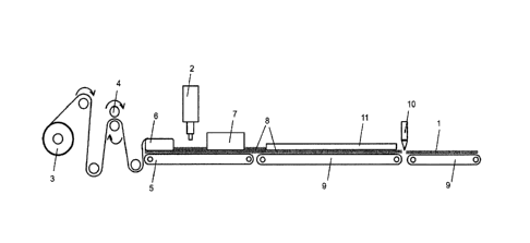
by means of an apparatus, which is schematically illustrated in Fig. 1.
In the apparatus, illustrated in Fig. 1, for manufacturing a profile element
1, a
polyethylene film is passed from a film stock 3 by means of a feed apparatus
over at
least one roll 4, where perforation takes place. The perforation is performed
by a
rotating roll 4 with attached needles. The film is then laid flat on a
conveying means 5
and passed over a forming shoulder 6, where the side-edge regions of the film
are
turned up in order that a free-flowing intumescent polyurethane material can
be
applied. The free-flowing polyurethane material is mixed by means of a casting
system
2 and applied to the film by uniform orthogonal dosing on the upper side of
the film.
The film is then passed by means of conveying means 5 to a thermal welding
system
7, where a first side-edge region of the film is joined with a second side-
edge region of
the film by thermal welding to produce a fish-fin weld seam. Thereafter the
tubular
CA 02978247 2017-08-30
- 16 -
profile element formed in this way is passed by means of conveying equipment 9
over
a reaction section 8, in which foaming of the polyurethane mixture takes
place. The
desired profile geometry is shaped by at least one metal profile 11. Thereupon
the
finished profile element 1 is passed to a cutting unit 10, where cutting of
profile element
.. 1 to the desired length takes place.
Figs. 2a to 2c show a preferred embodiment of a profile element 1 manufactured
according to the invention. Profile element 1 has two sealing regions la and 1
b, which
are positioned on the outer peripheries of connecting element lc. Sealing
regions la
and lb have a round profile and a solid profile, and connecting element lc has
a solid
profile. Sealing regions la and lb and connecting element lc consist of a
compressible
polyurethane foam (le), which optionally contains fire-protection additives.
Polyethylene film Id completely encloses the polyurethane foam.
Fig. 3 sketches the application of the embodiment of a profile element,
illustrated in Fig.
2a to 2b and manufactured according to the invention, for acoustic, smokeproof
and/or
fireproof sealing of connecting joints in drywalls. To seal the gap between a
ceiling 12,
channel profile 13 of a drywall studwork and gypsum boards 14, in the first
step, profile
element 1 is laid on the web of channel profile 13 and, in the second step, is
fastened
.. together therewith on ceiling 12 in the usual way, e.g. by screws or nails.
Then, in a last
step, gypsum boards 14 are applied on the flanges of channel profile 13 and
pushed
upward in the direction of ceiling 12, whereupon a gap remains between the top
edge
of gypsum board 14 and ceiling 12, which is filled with sealing regions la and
lb of
profile element 1, in order to permit vertical movement, for example, of
gypsum board
14. Thereby sealing regions la and lb are pressed together and thus seal the
gap
between ceiling 12 and channel profile 13 and the gap between ceiling 12 and
gypsum
board 14. Thus profile element 1 is positioned in the upper region of the
connecting
joint and is configured to seal the joint from the outside.
.. As is obvious from the foregoing explanations, the inventive method is
suitable in
particular for manufacturing, in cost-effective, economic, continuous and
endless
CA 02978247 2017-08-30
- 17 -
manner, a profile element for acoustic, smokeproof and/or fireproof sealing of
connecting joints in drywalls, especially of expansion joints.
The inventive method and the inventive apparatus are characterized in
particular by the
.. following advantages compared with prior art systems:
Because of the uniform orthogonal dosing on the surface of the film, no
contamination
of possible process supply lines occurs, since the foam comes into contact
only with
the film and not with further apparatus components. Furthermore, the apparatus
permits quick setup for other dimensions and diameters of the desired profile
element,
e.g. by exchanging the forming shoulders and adjusting the film width as well
as the
desired length of the profile element, without laborious setup. The inventive
method
and the apparatus permit the manufacture of profile elements with a diameter
of
approx. 25 mm to approx. 70 mm and a length of up to 5 m.
Due to the flexible use of several metal profiles, the profile geometry can be
freely
configured, depending on the desired service area. The film of the profile
element
manufactured according to the invention simultaneously functions as a mounting
aid,
i.e. further mounting accessories are not necessary, and it is not removed
before use.
This further has the advantage that the profile element can be mounted quickly
and
that the foam is protected from sprayed or splashed water as well as during
installation.
Furthermore, the inventive method and device prevent the backing-up of the
material
compound that may occur in an already prefabricated tube during the
manufacturing
process, or they prevent insufficient material compound in the manufactured
joint cord.
Furthermore, the intermixing quality/homogeneity of the foam is not influenced
by the
shaping step.
As is also obvious from the foregoing explanations, the profile element
manufactured
according to the invention is particularly suitable for safely sealing a
building-structure
joint between two adjacent building parts in simple manner, especially against
sound
and/or smoke and optionally also against fire.
4
CA 02978247 2017-08-30
- 18 -
Furthermore, application is very mounting-friendly, since no additional
fastening of the
profile element, for example to the profile or to the ceiling, is necessary.
Accurately
fitting application of the profile element, for example against a profile, is
likewise
unnecessary, by virtue of the self-centering of the profile element during
mounting of
the profile on a building part. Mounting is therefore conceivably easy, and
the working
effort for mounting the profile element is greatly reduced. The profile
element
manufactured according to the invention therefore achieves safe and reliable
sealing of
joints between two building parts, especially between a profile of a dry-
construction
studwork and a building part adjacent thereto, such as, for example, a
ceiling, wall or
floor. In this connection, two-sided sealing can be achieved in only one
operation, by
providing a prefabricated profile element.
Furthermore, it has been shown that outstanding imperviousness can be achieved
with
the profile element manufactured according to the invention, since good
compressibility
of the sealing regions is ensured without additional auxiliary means by the
choice of the
sealing materials and/or geometric configuration. The profile elements
manufactured
according to the invention also make it possible to adjust the correct spacing
of gypsum
board from the connecting building part without additional auxiliary means, in
order to
achieve the said precompression.
By means of the profile element manufactured according to the invention, it is
also
possible to ensure that, merely by the choice of the sealing materials and/or
geometric
configuration, sufficient material is installed to ensure excellent
imperviousness with
maximum absorption of movement.
Furthermore, with the profile element manufactured according to the invention,
irregularities of the surface of a building part can be reliably sealed as
soon as one
building part is disposed on another building part, since the sealing elements
of the
joint-sealing tape are pressed sufficiently firmly against the surface of the
one building
part and at the same time against the side faces of the other building part.
In view of the foregoing, it is obvious that the objects of the invention have
been solved.
Since various modifications can be made to the method described in the
foregoing, to
the apparatus, to the profile element manufactured according to the invention
and to
CA 02978247 2017-08-30
- 19 -
the use thereof without departing from the scope of the invention, it is
intended that all
subject matters contained in the foregoing description be interpreted as
illustrative and
not in a restrictive sense,