Note: Descriptions are shown in the official language in which they were submitted.
1 A MECHANICAL FINGER
2
3 This invention claims priority from provisional patent application S/N
61/780,622
4 filed 13 March, 2013 for a Prosthetic Finger Design having a common sole
inventor.
6
7 STATEMENT REGARDING FEDERALLY SPONSORED
8 RESEARCH OR DEVELOPMENT
9 This invention was not developed with Government funded effort.
11 FIELD OF THE INVENTION
12
13 This invention relates to the field of prosthetic appliances made for
and used by
14 human amputees and more particularly to those amputees that have lost one
or
more fingers on a hand.
16
17 BACKGROUND OF THE INVENTION
18
19 US patent 8100986 issued on 01/24/2012 to inventor Gregor Puchhammer of
Vienna (AT) shows a mechanical prosthetic finger with a proximal member, a
21 medial member and a distal member all mounted pivotally on one another. A
22 moveable balance arm is connected via leavers to the proximal member and
to the
23 distal member. However, the Puchhammer '986' reference does not show the
24 simpler arrangement of a screw nut assembly in a proximal element cavity
having
a left and right pivot boss extending through the left and right slots in the
proximal
26 element cavity. The left and right pivot boss are each sized to provide
free
CA 2978259 2020-02-19 1
1 longitudinal movement within its respective left guide and right slots so as
to
2 prevent the screw nut assembly from rotating in the proximal element
cavity as the
3 screw nut assembly is moved longitudinally in the proximal element cavity by
an
4 axial screw drive.
6 US patent 5,888,246 issued 03/30/1999 to inventor David J. Gow of
Edinburgh
7 (GB) from application 08/702,605 filed 03-10-1995. The '246' patent is
related art
8 but it fails to show a screw nut assembly in a proximal element cavity
having a left
9 guide and pivot boss extending through the left slot and a right guide and
pivot
boss extending through the right slot of the proximal element cavity. The left
and
11 right pivot boss are each sized to provide free longitudinal movement of
the left
12 and right boss toward the distal element or toward the knuckle end of
the proximal
13 element within its respective left guide or right guide while preventing
the screw
14 nut assembly from rotating in the proximal element cavity as the screw nut
assembly is moved longitudinally in the proximal element cavity by a direct
16 longitudinal screw drive.
17
18 Mechanical fingers for artificial hands require various features to best
perform the
19 functions for an upper limb prosthetic user. The required features and
functions
include a high strength force generator, a light weight, good reliability,
adequate
21 speed, and a size that permits a cover that provides a natural appearance.
These
22 features are made difficult to include by the small space available inside
an
23 individual finger.
24
Another feature that is difficult to achieve in the design of a prosthetic
mechanical
26 finger is the short section where the prosthetic finger attaches to the
residual end of
27 the finger on the patient. Previous embodiments have placed the force
generators
CA 2978259 2020-02-19 2
1 or a part of the drive mechanism inside the build height which extends
the length
2 of the prosthetic to a position that is outside of the natural envelope
of a finger. A
3 longer than natural build height tends to result in fewer patients being
fitted with a
4 prosthetic finger. The shorter build height made possible by the invention
is
expected to improve the market acceptance of the prosthetic with expanded
sales
6 including sales to female s and teenagers.
7
8 Another feature made possible by the invention prosthetic is a reduced cost
9 flowing from its reduced complexity. Earlier embodiments have higher part
counts
with parts of significant complexity that contributed to a higher price for
the
11 prosthetic.
12
13 SUMMARY OF THE INVENTION
14 It is an object of the present invention to solve or reduce many of the
problems
stated above. The mechanical finger as taught by this disclosure, in a first
16 embodiment that comprises the following components: a knuckle, a proximal
17 element, a rod, a screw nut boss, a force generator with an axial drive
shaft driving
18 a screw that is axially coupled to the screw nut assembly, and a frame
means for
19 coupling the knuckle to the stump or residual limb of the patient. The
knuckle is
coupled to the frame and has a first and second pivot separated by a first
21 predetermined distance. The proximal element has a knuckle end and a
distal end.
22 The knuckle end of the proximal element is coupled to the knuckle first
pivot. The
23 proximal element provides a third pivot. The third pivot is located on
the proximal
24 element at a variable longitudinal distance from the first pivot.
26 It should be understood that the each of the three pivots characterized
herein, and
27 later a fourth pivot, are characterized in the structure of the
invention mechanical
CA 2978259 2020-02-19 3
1 finger by a corresponding left and right counterpart, each left and right
counterpart
2 being axially aligned, the axis of each pivot being normal to a plane
that contains
3 the longitudinal axis of the axial screw drive to the screw nut assembly.
4
The rod having a near end pivotally coupled to the knuckle second pivot and a
far
6 end of the rod is pivotally coupled to the third pivot. A screw drives
the screw nut
7 boss. The force generator is coupled to or reference to the proximal
element, and
8 more particularly to the near end or knuckle end of the proximal element
cavity.
9 The screw is coupled to the third pivot to change the variable
longitudinal distance
between the third pivot and the first pivot in response to a command from a
11 controller to the force generator.
12
13 A distal element is pivotally coupled to the proximal element at a fourth
pivot.
14 The distal element rotates with respect to the proximal element in response
to a
change in the variable distance between the third pivot and the first pivot.
The
16 distal element further has at least a first phalange pivotally coupled to
the fourth
17 pivot on the proximal element. Each phalange has a distal element slot
18 characterized to receive a screw nut boss through a proximal element slot
then
19 passing through the distal element slot.
21 Movement of the screw nut boss toward the knuckle results in a counter
clockwise
22 torque applied to the distal element around the fourth pivot as the
screw nut boss
23 engages the wall of the distal element slot. Movement of the screw nut boss
24 toward the distal end of the proximal element results in a clockwise
torque applied
to the distal element around the fourth pivot as the screw nut boss engages
the wall
26 of the distal element slot. In another alternative embodiment, the
mechanical
27 finger comprises a frame coupled to the knuckle and formed to receive and
be
CA 2978259 2020-02-19 4
1 attached to the residual limb of a patient. The mechanical finger also
has an elastic
2 or spring element extending in tension from the distal element to the
proximal
3 element to add to the grip force of the finger as it closes and to help
to maintain a
4 limited closed grip on the object grasped as the power to the force
generator is
interrupted.
6
7 The screw nut assembly within the proximal element cavity has a left guide
and
8 pivot boss extending through a left slot and a right guide and pivot boss
extending
9 through a right slot, each guide and pivot boss extending through its
respective
slot. As explained above, the force generator or motor rotates the screw that
is
ii engaged with the screw nut assembly. The screw nut assembly carries the
left and
12 right pivot boss in its slot, each pivot boss being sized to provide
free longitudinal
13 movement within its respective left guide and right guide to prevent the
screw nut
14 assembly from rotating in the proximal element cavity. The rotation of
the screw is
transferred into a linear movement of the third pivot as the screw nut
assembly is
16 moved longitudinally through the proximal element cavity.
17
18
CA 2978259 2020-02-19 5
1 BRIEF DESCRIPTION OF THE DRAWINGS
2
3 An example of a mechanical finger embodying the present invention will
now be
4 described in greater detail with reference to the accompanying drawings,
in which;
6 FIG 1 a shows a schematic stick drawing of the mechanical finger in the
fully open
7 position
8 FIG lb shows a schematic stick drawing of the mechanical finger in a
partially
9 flexed position
FIG lc shows a schematic stick drawing of the mechanical finger in a fully
flexed
11 position
12 FIG 2a is a perspective view of the mechanical finger shown in the fully
open
13 position
14 FIG 2b is a perspective view of the mechanical finger shown in a
partially flexed
position
16 FIG 2c is a perspective view of the mechanical finger shown in fully flexed
17 position
18 -- FIG 3a shows a partial sectional perspective view of the mechanical
finger in the
19 fully open position, showing the drive mechanism
FIG 3b shows a partial sectional perspective view of the mechanical finger in
the
21 partially closed position, showing the drive mechanism
22 FIG 3c shows a partial sectional showing the drive mechanism in a
perspective
23 view of the mechanical finger in the fully closed position,
24 FIG 4a is a perspective view of the mechanical finger,
FIG 4b is a perspective exploded view of FIG 4a,
26 FIG 5a shows a plan view of the mechanical finger with a section line A-
A
27 FIG 5b shows the section view A-A
CA 2978259 2020-02-19 6
1 FIG 6a is a perspective view of the distal element
2 FIG 6b shows an exploded view FIG 6a
3 FIG 7a is a perspective view of the force generator and the drive
mechanism,
4 FIG 7b shows an exploded view of FIG 7a
s FIG 8a is a perspective view of the proximal element,
6 FIG 8b shows an exploded view of FIG 8a
7 FIG 9a is a perspective view of the knuckle to frame mount and frame
mount
8 assembly,
9 FIG 9b shows an exploded view of FIG 9a
FIG 10a shows a side view of the rod
ii FIG 10b shows a plan view of the rod
12 FIG 10c shows an exploded view of the rod with bearings
13 FIG 10d shows the rod with bearings fitted
14 FIG lla shows a side view of the screw nut
FIG 11 b shows a front view of the screw nut
16 FIG 11c shows a perspective view of the screw nut with x2 washers
17 FIG lld shows a perspective view of the screw nut with x2 washers
18 FIG lie shows a perspective view of the screw nut with x4 washers fitted
19 FIG llf shows a perspective view of the screw nut with x4 washers fitted
FIG 12a shows the sprung element side view
21 FIG 12b shows the sprung element in perspective
22 FIG 13a is a perspective and partial view of the proximal element and
screw nut in
23 the fully open position
24 FIG 13b is a perspective and partial view of the proximal element and
screw nut in
the partially closed position
26 FIG 13c is a perspective and partial view of the proximal element and
screw nut in
27 the fully closed position
CA 2978259 2020-02-19 7
1 FIG 14a is a perspective and partial view of the proximal element, screw
nut and
2 distal element in the fully open position
3 FIG 14b is a perspective and partial view of the proximal element, screw
nut and
4 distal element in the partially closed position
FIG 14c is a perspective and partial view of the proximal element, screw nut
and
6 distal element in the fully closed position
7 FIG 15a is a perspective and partial view of the proximal element, rod
and distal
8 element in the fully open position
9 FIG 15b is a perspective and partial view of the proximal element, rod
and distal
element in the partially closed position
ii FIG 15c is a perspective and partial view of the proximal element, rod
and distal
12 element in the fully closed position
13 FIG 16a shows a partial view of the proximal element, rod and distal
element in
14 the fully open position, the distal element having an alternative slot
design
FIG 16b shows a partial view of the proximal element, rod and distal element
in
16 the fully open position, the distal element having an alternative slot
design and the
17 distal element being pushed closed
18
19 DESCRIPTION OF THE INVENTION
21 The invention Mechanical Finger will now be discussed with reference to
FIG. 1
22 through FIG. 16b with FIG. la being a simplified stick drawing showing
frame 10
23 which attaches to the amputee residual limb, and the knuckle 12 attached to
the
24 frame 10. The knuckle 12 has a first pivot 14 and a second pivot 16. The
knuckle
end of the rod 18 is attached to the knuckle 12 at the second pivot 16. The
distal
26 end of the rod 18 is attached to the rod to screw nut boss 22. The
proximal element
27 24 contains the force generator 26 that is connected to and can push and
pull the
CA 2978259 2020-02-19 8
1 screw nut boss 22 in a longitudinal direction. The force generator 26 is
powered by
2 the battery 28, and controlled by the control sensor 32 and the processor
34. The
3 proximal element 24 has a fourth pivot 36 which connects the proximal
element 24
4 to the distal element 38. The proximal element 24 has a proximal element
slot 42
that guides the screw nut boss 22 in a longitudinal direction. The distal
element 38
6 has a distal element slot 47 which contains the screw nut boss 22. As the
force
7 generator actuates the screw nut boss 22, the distal element slot 47
accommodates
8 the linear movement of the screw nut boss 22 as it travels through the
arc from the
9 fourth pivot 36 and pulls the distal element 38 closed. The elastic or
spring
element 46 is connected to the distal element 38 and the proximal element 24
to
11 maintain force when the power is interrupted.
12
13 FIG lb being a simplified stick drawing showing the force generator 26
as it has
14 pulled the screw nut boss 22 towards the knuckle 12 to a part closed
position of the
mechanical finger. The screw nut boss 22 travels through the proximal element
slot
16 42, as it does the distance between the screw nut boss 22 and the first
pivot 14 gets
17 shorter, because the screw nut boss 22 and the second pivot 16 are
always the same
18 distance apart due to the length of the rod 18, the first pivot 14 is
actuated towards
19 a closed position. The screw nut boss 22 is connected to the distal
element slot 47.
As the screw nut boss 22 is pulled towards the knuckle 12 the distal element
slot
21 47 is rotated around the fourth pivot 36.
22
23 FIG lc is another schematic simplified stick drawing showing the force
generator
24 26 as it has pulled the screw nut boss 22 towards the knuckle 12 to a
fully closed
position of the finger.
26
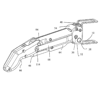
CA 2978259 2020-02-19 9
1 FIG 2a is a perspective view of the mechanical finger assembly shown if
greater
2 detail than FIG 1 in the fully open position. The frame 10 is connected to
the
3 knuckle to frame mount 48 which connects the left knuckle 52 and the right
4 knuckle 54 to the frame 10. The left knuckle 52 contains the left second
pivot 56
and the left first pivot 58. The left rod 68 is shown coupled to and extending
from
6 the left third pivot 114 to the left second pivot 56. The left proximal
element 64 is
7 connected to the left knuckle 52 at left first pivot 58. The left
proximal element 64
8 is connected to the left distal element 66 at the left fourth pivot 94.
The elastic or
9 spring element 46 is connected in tension to the left distal element 66
and the left
proximal element 64.
11
12 FIG 2b is a perspective view of the mechanical finger assembly shown in
the
13 partially closed position
14
FIG 2c is a perspective view of the mechanical finger assembly shown in the
fully
16 closed position.
17
18 FIG 3a shows a partial sectional view of the mechanical finger. The left
proximal
19 element 64, the left distal element 66 and the left rod 68 have been
removed for
clarity. Inside the left proximal element 64 and the right proximal element 72
is the
21 force generator 26 which is connected to the screw 74. When the force
generator
22 26 receives a drive command it rotates to move the screw 74 in a clockwise
or
23 counter clockwise direction. The screw nut 76 is threaded onto the screw
74. The
24 screw nut 76 has a left third pivot boss 62 which extends through the
left proximal
element slot 78 (not shown). Although the left proximal element slot 78 is not
26 shown on FIG. 3a, 3b or 3c, that feature can be seen on FIG. 13a, 13b and
13c.
27 The right third pivot boss 82 (not shown) extends though the right proximal
CA 2978259 2020-02-19 10
1 .. element slot 84 (not shown). As the left and right pivot bosses extend
through the
2 respective left and right proximal element slots, they serve to prevent
the screw nut
3 .. 76 from rotating inside the proximal element cavity in response to
rotation of the
4 screw 74 as the prosthesis is commanded to operate. Rotation of screw 74
in the
screw nut 76 exerts a torsional force on the screw nut 76. By preventing the
screw
6 nut 76 from rotating, the torque applied to the screw nut 76 is converted
and
7 .. combined with the inclined plane of the screw thread to provide an axial
linear
8 .. force to the third pivot 21 (shown in Figs la-c) via the left and right
boss as they
9 extend through the left proximal element slot 78 (not show) and right
proximal
element slot 84 (not shown).
11
12 FIG 3b shows a partial view of the mechanical finger in the partially
closed
13 position with the screw nut 76 being at its middle position on the
length of the
14 screw 74. FIG 3c shows a partial sectional view of the mechanical finger
in the
fully closed position with the screw nut 76 moved to a limit on screw 74
toward
16 the motor or force generator 26.
17
18 FIG 4a is a perspective view from above, of the mechanical finger. FIG
4b
19 .. is an exploded view of FIG 4a. A sensor 86 is positioned in the proximal
element
cavity between the rear or knuckle end of the motor and the knuckle to frame
21 mount 48. The sensor 86 measures the longitudinal position or distance
that the
22 .. screw nut 76 is at or has traveled along the length of the screw 74
driven by the
23 force generator 26. The force generator 26 is connected to and rotates the
screw
24 74.
26 As stated earlier, the screw 74 is threaded into the screw nut 76. The
screw nut 76
27 has a left third pivot boss 62 and a right third pivot boss 82. These
elements
CA 2978259 2020-02-19 11
. .
1 constitute the drive mechanism. The drive mechanism is contained inside the
2 proximal element cavity formed by the left proximal element 64 and the right
3 proximal element 72. In operation, as the force generator 26 receives a
command
4 or drive signal, the screw 74 turns, the screw nut 76 is prevented from
turning by
the left proximal element slot 78 and the right proximal element slot 84 shown
on
6 FIG's 8a and 8b. The slots 78 and 84 allow a linear movement of the screw
nut 76
7 along the threaded length of the screw 74.
8
9 With continuing reference to the exploded view of Fig. 4b, the left
knuckle 52 is
connected to the left proximal element 64 at the left first pivot 58. The
right
11. knuckle 54 is connected to the right proximal element 72 at the right
first pivot 88
12 (not shown). The left knuckle 52 is connected to the right knuckle 54.
The knuckle
13 to frame mount 48 is connected to the left knuckle 52 and right knuckle 54.
The
14 knuckle to frame mount 48 is connected to the frame 10.
16 The left distal element 66 is connected to the right distal element 92. The
left
17 distal element 66 and right distal element 92 are pivoted on the proximal
element
18 at the right fourth pivot 96 (not shown) which is formed by the left fourth
pivot
19 boss 126 capturing the left fourth pivot aperture 132 (not shown), and the
left
fourth pivot 94 (not shown) which is formed by the right fourth pivot boss 128
21 capturing the right fourth pivot aperture 134 (not shown). The left
fourth pivot 94
22 and the right fourth pivot 96 facilitate the rotational movement of the
distal
23 elements 66, 92 relative to the proximal elements 64, 72.
24
The left rod 68 has left second pivot boss 138 that captures the left second
pivot
26 aperture 146 to form the left second pivot 56. The right rod 98 has
right second
CA 2978259 2020-02-19 12
1 pivot boss 139 that captures the right second pivot aperture 148 to form
the right
2 second pivot 102.
3
4 The left rod 68 has a left third pivot aperture 136 that is received by
the left third
pivot boss 62. The right rod 98 has a right third pivot aperture 137 that
receives
6 the right third pivot boss 82.
7
8 FIG 5a shows a plan view of the mechanical finger with a section line A-A
and
9 FIG 5b shows the sectional view of FIG 5a taken on section line A-A. The
frame
10 is shown connected to the knuckle to frame mount 48 which is shown
11 connected to the right knuckle 54. The sensor 86 is depicted inside and
to the rear
12 of the force generator 26. The microprocessor 104 is shown on top of the
force
13 generator 26. The bearing for screw knuckle end 106 and the screw 74 is
attached
14 to the left end of the force generator 26. The screw 74 is threaded
through the
screw nut 76. A bearing for screw distal end 108 is shown that holds the
distal end
16 of the screw 74. An elastic or spring element 46 is shown that is joined
to the left
17 proximal element 64 (not shown) and right proximal element 72, and to the
left
18 distal element 66 (not shown) and right distal element 92. The bearings
for screw
19 knuckle end 106 and the bearing for screw distal end 108 protect the
screw 74 and
the force generator 26 from radial and linear loading.
21
22 FIG 6a shows the left distal element 66 and the right distal element 92
with the
23 assembly screws 112 holding the two in contact with each other to form
the distal
24 element 38. The left distal element 66 has a left distal element flange
122. The left
distal element flange 122 has a left fourth pivot aperture 132 and a left
distal
26 element slot 116. The right distal element 92 has a right distal element
flange 124.
27 The right distal element flange 124 has a right fourth pivot aperture
134 and a right
CA 2978259 2020-02-19 13
1 distal element slot 118. FIG 6b shows an exploded view of FIG 6a. It may
be
2 possible to reverse the position and function of the left distal element
slot 116 and
3 the right distal element slot 118 with the left fourth pivot aperture 132
and the right
4 fourth pivot aperture 134.
6 FIG 7a shows the force generator 26 and drive mechanism assembly. The sensor
7 86 is connected to the force generator 26. The force generator 26 is
connected to
8 and drives the screw 74. The screw nut 76 is threaded onto the screw 74. The
9 bearing for screw knuckle end 106 and the bearing for screw distal end 108
are
designed to protect the force generator 26 from axial (thrust) and radial
loading.
ii FIG 7b is an exploded perspective view of FIG 7a
12
13 FIG 8a is a perspective view of the assembled proximal formed from a left
14 proximal element 64 and a right proximal element 72. FIG 8b also shows the
assembly screws 112 used to couple the left and right sides to form the
proximal
16 element 24.
17
18 The left fourth pivot boss 126 is shown above the left proximal element
slot 78.
19 The right fourth pivot boss 128 is shown above the right proximal
element slot 84.
The left fourth pivot boss 126 and right fourth pivot boss 128 each
respectively
21 extend through the respective left and right fourth pivot apertures 132,
134 on the
22 respective left and right flanges 122, 124 of the distal element.
23
24 The left fourth pivot boss 126 with the left fourth pivot apertures 132
(shown on
Fig 6.b), and the right fourth pivot boss 128 with the right fourth pivot
apertures
26 134 (shown on Fig 6.b), in combination form the fourth pivot 36 (shown on
Fig
27 1.a). The left proximal element 64 has a left first pivot boss 156 that
is received by
CA 2978259 2020-02-19 14
1 a left first pivot aperture 152 shown on FIG 9a and 9b. The right
proximal element
2 72 has a right first pivot boss 158 (not shown) that is received by a
right first pivot
3 aperture 154 also shown on FIG 9a and 9b. The combination of left first
pivot
4 boss 156 into the left first pivot aperture 152 and the right first pivot
boss 158 into
the right first pivot aperture 154 form the first pivot 14. FIG 8b shows an
exploded
6 view of FIG 8a.
7
8 FIG. 9a is a perspective view of the knuckle 12 formed from a left
knuckle 52 and
9 a right knuckle 54 pair of components. The knuckle to frame mount 48 and
the
frame 10 are also shown. The left knuckle 52 is joined to the right knuckle 54
with
11 two assembly screws 112. The knuckle to frame mount 48 is attached to
the left
12 knuckle 52 and right knuckle 54 with screws 112. The frame 10 is
attached to the
13 knuckle to frame mount 48 with screws 112. The left knuckle 52 has a left
first
14 pivot aperture 152. The right knuckle 54 has a right first pivot aperture
154 as
discussed in connection with the above discussion of FIG 8a and FIG 8b.
16
17 FIG 9b shows an exploded view of 9a.
18
19 FIGs 10a-10d shows the left rod 68. The left rod 68 is the same as the
right rod 98
(not shown). The left rod 68 contains a left third pivot aperture 136 that
fits onto
21 left third pivot boss 62 (not shown) to form left third pivot 114. The
right rod 98
22 (not shown) contains a right third pivot aperture 137 that fits onto
right third pivot
23 boss 82 to form right third pivot 120. The combination of the left rod
68 which
24 contains the left third pivot aperture 136 with the left third pivot
boss 62 and the
right third pivot aperture 137 with the right third pivot boss 82 form the
third pivot
26 21 located on the screw nut boss 22.
27
CA 2978259 2020-02-19 15
1 The left rod 68 also contains the left second pivot boss 138. The left
second pivot
2 boss 138 connects the left rod 68 to the left second pivot 56. To
increase efficiency
3 the left rod 68 has a rod aperture bearing 142 inserted into the left third
pivot
4 aperture 136, and rod boss bearing 144 inserted onto the left second pivot
boss
138. The right rod 98 mirrors the described arrangement of the left rod 68.
6
7 The stiffness of the rod contributes to the ability of the mechanical
finger to deliver
8 a grip that could exceed design limits. It may be possible to design the
rods so as
9 to experience distortion when a design limit is exceeded so as to
preclude damage
to the structure elements. One possible design embodiment for this purpose
could
ii be to design the rods to have a corrugated or curved feature fabricated
into the
12 surface of the rod, or to design the rod to have a spring characteristic.
The
13 combination of the left second pivot boss 138 with the left second pivot
aperture
14 146 along with the combination of an identical right second pivot boss
139 (not
shown) with the right second pivot aperture 148 form the second pivot 16 shown
in
16 FIG's la-lc.
17
18 FIG ha is a side view of the screw nut 76. FIG 11b is a front view of
the screw
19 nut 76. FIG 11c is an exploded view of the screw nut 76 showing the left
third
pivot boss 62 and the right third pivot boss 82 with sleeve bearings ready for
21 installation on the bosses and aligned on each of the bosses.
22
23 FIG lid is a perspective view of the screw nut 76, with sleeve bearings
on the left
24 and right third pivot boss 82. The left third pivot boss 62 and the
right third pivot
boss 82, each with sleeve bearings installed are received by the respective
proximal
26 element slots 78, 84 (not shown), and the outer surface of the bearings
are sized to
27 ride in the proximal element slots.
CA 2978259 2020-02-19 16
. .
1
2 FIG lie is an exploded view of the screw nut 76 with the left third pivot
boss 62
3 and the right third pivot boss 82, each being ready to receive a bushing
that is
4 stopped by the edge of an earlier sleeve bearing.
6 FIG llf is a perspective view showing the screw nut assembly ready for
assembly,
7 the bushing on each of the third pivot bosses 62, 82 receiving the
respective distal
8 element slot for third pivot boss left and right side 116, 118 (not shown).
The
9 sleeves and bearings are added to space the distal element aperture for
screw nut
boss left and right side from the respective outer surface of the proximal
element
ii 24 and add an increase in efficiency between the left third pivot boss
62 and the
12 right third pivot boss 82 and the distal element slot left and right
side 116, 118.
13
14 FIG 12a is a side view of a single elastic or spring element 46, and FIG
12b is a
perspective view of a pair of elastic or spring elements 46.
16
17 FIG 13a is a partial perspective view of the distal end of the left
proximal element
18 64, the right proximal element 72 being partially unseen behind the left
side. The
19 left and right sides are assembled together with the screw 74 appearing
in FIG 13c.
As shown in FIG 13a, as the mechanical finger is fully opened, the left third
pivot
21 boss 62 is at the distal end of the left proximal element slot 78.
22
23 FIG 13b is a partial perspective view of the left proximal element 64
and the right
24 proximal element 72 behind the surface, the two being assembled together
with the
screw 74 and screw nut 76 in the half way closed position.
26
CA 2978259 2020-02-19 17
1 FIG 13c a partial perspective view of the left proximal element 64 and
the right
2 proximal element 72 assembled together with the screw 74 and screw nut 76
of the
3 mechanical finger being in the fully closed position.
4
FIG 14a shows a partial view of the proximal element to distal element joint
with
6 the finger in a fully opened configuration. The left third pivot boss 62 is
in the
7 lower part of the left distal element slot 116 to the left of the left
fourth pivot 94.
8
9 FIG 14b shows that the left third pivot boss 62 has moved approximately
half way
through its actuation travel. The left distal element 66 is pulled by the left
third
11. pivot boss 62 in a counter clockwise rotation towards the knuckle 12.
As the left
12 third pivot boss 62 moves from the position shown in FIG 14a, to FIG 14b
and
13 then to FIG 14c within the left proximal element slot 78 (not shown),
the left third
14 pivot boss 62 applies a force to the edge of the left distal element
slot 116 that
results in a torque applied to the left distal element 66 forcing it to pivot
and rotate
16 in a counter clockwise rotation around the left fourth pivot 94. The
left third pivot
17 boss 62 touches the inner surface or perimeter of the left distal
element slot 116
18 with a sliding or rolling surface on a fixed slot surface only
traversing an arc path
19 along the inner surface of the left distal element slot 116. The arc
movement of
the left third pivot boss 62 is accommodated by the left distal element slot
116 as
21 the left third pivot boss 62 travels upwards in the left distal element
slot 116
22 towards the left fourth pivot 94. In FIG 14c the finger is fully closed;
the left third
23 pivot boss 62 can be seen sitting in the lower part of the left distal
element slot 116
24 away from the left fourth pivot 94.
26 It will be understood that the right distal element 92 has the same
relationship and
27 movement with the right third pivot boss 82 (not shown) as the left
distal element
CA 2978259 2020-02-19 18
1 66 has with the left third pivot boss 62. FIG 14a-14c also shows the elastic
or
2 spring element 46 which is attached and connects the left proximal
element 64 and
3 the right proximal element 72 to the left distal element 66 and the right
distal
4 element 92. The elastic or spring element 46 is in tension, so when the
power is
interrupted or paused, the elastic or spring element 46 together with the
resistance
6 in the force generator 26 and the drive mechanism operate to resist and
prevent the
7 mechanical finger from opening. If the mechanical finger is holding an
item at the
8 time of the interruption, the item held will remain secured in the grip of
the
9 mechanical finger, or fingers as the case may be.
ii FIGs 15a-15c are distinguished from FIGs 14a - 14c by showing the addition
of
12 left rod 68 in the FIGs 15a - 15c series. FIG 15a shows a partial view
of the left
13 proximal element 64 and the right proximal element 72 receding into the
image.
14 The left proximal element 64 is assembled together with the left rod 68.
The left
rod 68 is connected to the left third pivot boss 62 (not shown) at the left
third pivot
16 114. FIG 15a shows the mechanical finger in a fully open position. 15b
shows the
17 mechanical finger in a partially closed position and FIG 15c shows the
mechanical
18 finger in a fully closed position.
19
FIG 16a shows the fourth pivot with the distal element having an alternative
21 embodiment ¨ the distal element has a more elongated left distal element
slot 116
22 and right distal element slot 118 (not shown). The left third pivot boss
62 and the
23 right third pivot boss 82 (not shown) sit inside a more elongated left
distal element
24 slot 116 and the right distal element slot 118 (not shown). FIG 16b
shows the left
distal element 66 and the right distal element 92 (not shown) receiving an
26 unexpected load and being pushed downwards by the force. Since the left
distal
27 element slot 116 and right distal element slot 118 (not shown) are more
elongated
CA 2978259 2020-02-19 19
1 the left distal element 66 and the right distal element 92 (not shown)
are able to be
2 pushed downwards, this can be used as a feature to protective the mechanical
3 finger from accidental external shock.
4
While certain specific relationships, materials and other parameters have been
6 detailed in the above description of a preferred embodiment, those can be
varied,
7 where suitable, with similar results. Other applications and variations
of the present
8 invention will occur to those skilled in the art upon reading the present
disclosure.
9 Those variations are also intended to be included within the scope of
this invention
as defined in the appended claims.
CA 2978259 2020-02-19 20
= ,
List of Parts
10¨Frame
12¨Knuckle
14¨First pivot
16¨Seco1Id pivot
18--Rod
21¨Third pivot
22¨Screw nut boss
24-- Proximal element
26¨Force generator
28¨Battery
32¨Control sensor
= Processor
36---Fourth pivot
38¨Distal element
42¨Proximal element slot
44¨Distal element pivot aperture
45¨Distal element follower
46¨Elastic or spring element
47¨Distal element slot
48¨Knuckle to frame mount
52 -Lett knuckle
54¨Right knuckle
56¨Left second pivot
58¨First pivot
62....-Left third pivot
64--Left proximal element
66¨Left distal element
68¨Left rod
72- -Right proximal element
74-- Screw
76¨Screw nut
78¨Left proximal element slot
82¨Right third pivot
84¨Right proximal element slot
86-- Sensor
88¨Right knuckle to proximal element pivot
92¨Right distal element
94¨Left fourth pivot
96¨Right fourth pivot
98¨Right rod
102¨Right knuckle to rod pivot
104¨Microprocessor
106--Bearing for screw knuckle end
HIS¨ Rearing fur screw distal end
112¨Assembly screws
114¨Lett rod to third pivot
116-141 distal element slot
118 --Right dkital element slot
120--Right rod to third pivot
122¨Left distal element area
area
CA 2978259 2020-02-19 21
126¨Left fourt pivot boss
128¨Right fourth pivot boss
I32.--Left fourth pivot aperture
134¨Right fourth pivot aperture
136¨Left third pivot aperture
137¨Right third pivot aperture
138¨Left second pivot boss
139¨ Right rod boss
142¨Rod aperture bearing
144---Rod boss bearing
146--Left second pivot aperituv
148¨Right second pivot aperture
152¨Left first pivot aperture
154¨Right first pivot aperture
156--Left first pivot boss
158¨Right first pivot boss
160--Elongated I tote
162¨Cylindrical Hole
164 Proximal element cavity
CA 2978259 2020-02-19 22