Note: Descriptions are shown in the official language in which they were submitted.
SYSTEMS AND METHODS FOR FACILITATING SEED FEEDER FILLING
BACKGROUND
[0002] Many bird feeders configured to dispense seeds are notoriously
burdensome to fill.
Generally, such bird feeders are suspended from a tree or other structure
where birds may
access the seeds. When the seed supply is depleted, a user has to remove the
suspended bird
feeder and carry it to where the user's stock of seed is stored for refilling.
After the bird feeder
is refilled, the user then carries the bird feeder back to the tree or
structure and rehangs it.
Having to make multiple trips each time a bird feeder is empty often deters
users from refilling
the bird feeder regularly and detracts from the enjoyment of the hobby.
Alternatively, some
users prefer to carry the stock of seed to the bird feeder for refilling.
Having to carry an often
heavy bag of seed back and forth similarly deters users from refilling the
bird feeder regularly
and detracts from the enjoyment of the hobby. Moreover, refilling bird feeders
in one of these
manners routinely causes seed spillage. It is with these observations in mind,
among others,
that various aspects of the present disclosure were conceived and developed.
BRIEF SUMMARY
[0003] Implementations described and claimed herein address the foregoing
problems by
providing systems and methods for facilitating filling of bird feeders
configured to dispense
seeds. In one implementation, an easy fill bird feeding system includes one or
more easy fill
bird feeders and one or more birdseed totes.
[0004] In one implementation, an easy fill bird feeder includes a body
extending from a
proximal end to a distal end. The body defines a reservoir with a body opening
into the
reservoir. The opening is disposed at the proximal end of the body. A cap
assembly is
connected to the body at the proximal end and covers the opening. The cap
assembly includes
a hinge engaging a lid
I
CA 2978952 2019-01-31
CA 02978952 2017-09-06
WO 2016/149709 PCMJS2016/023471
reservoir. The opening is disposed at the proximal end of the body. A cap
assembly is
connected to the body at the proximal end and covers the opening. The cap
assembly includes a
hinge engaging a lid to a cap base at a first side, with the hinge creating a
rotation path for the lid
between an open position and a closed position. The lid is releasably
connected to the cap base
at a second side in the closed position. A cap opening is defined by the cap
base and provides
access to the reservoir through the body opening. A spring assembly applies a
bias on the lid
towards the open position. The easy fill bird feeder includes a releasor of
the cap assembly.
Movement of the releasor disconnects the lid from the cap base at the second
side, and the bias
of the spring assembly moves the lid from the closed position to the open
position upon the lid
being disconnected from the cap base. The bias of the spring assembly holds
the lid in the open
position, providing access to the reservoir through the cap opening.
[0005] In another implementation, a depression is received of a release button
on a cap assembly
connected to a body at a proximal end. The body defines a reservoir, and the
cap assembly has a
cap opening providing access to the reservoir. A lid of the cap assembly is
released at a first side
upon the depression of the release button. The lid is moved from a closed
position to an open
position using a bias of a spring assembly upon the release of the lid. The
lid moves from the
closed position to the open position along a rotation path created by a hinge
at a second side.
The lid is held in the open position by the spring bias, and the open position
provides access to
the reservoir through the cap opening. Birdseed is received through the cap
opening into the
reservoir.
[0006] In still another implementation, a birdseed tote includes a pair of
opposing sidewalls each
extending from a distal end to a proximal end and between a front end and a
back end. A distal
surface connects the distal ends of the pair of opposing side walls, and a
back wall connects the
back ends of the pair of opposing side walls. A neck extends from the front
ends of the pair of
opposing side walls. The pair of opposing sidewalls, the back wall, the distal
surface, and the
neck form a tote body configured to hold birdseed. The tote body has a
proximal edge extending
along a plane. The neck includes a neck surface extending along a contour from
the distal
surface to a spout. An axis line of the spout extends parallel to the plane of
the proximal edge of
the tote body. The neck surface is shaped to direct the birdseed from the
distal surface through
2
CA 02978952 2017-09-06
WO 2016/149709 PCT/US2016/023471
an opening in the spout without an orientation of the plane extending past a
perpendicular angle
to a target.
[0007] Other implementations are also described and recited herein. Further,
while multiple
implementations are disclosed, still other implementations of the presently
disclosed technology
will become apparent to those skilled in the art from the following detailed
description, which
shows and describes illustrative implementations of the presently disclosed
technology. As will
be realized, the presently disclosed technology is capable of modifications in
various aspects, all
without departing from the spirit and scope of the presently disclosed
technology. Accordingly,
the drawings and detailed description are to be regarded as illustrative in
nature and not limiting.
BRIEF DESCRIPTION OF THE DRAWINGS
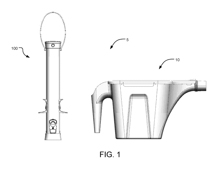
[0008] Figure 1 illustrates an example easy fill bird feeding system including
an easy fill bird
feeder and a birdseed tote.
[0009] Figure 2 shows an isometric view of an example easy fill bird feeder.
[0010] Figures 3A-3C illustrate side, front, and back views, respectively, of
the bird feeder of
Figure 2.
[0011] Figures 4A and 4B show top and bottom views, respectively, of the bird
feeder of Figure
2.
[0012] Figure 5 is a detailed view of an example cap assembly of the bird
feeder of Figure 2.
[0013] Figure 6 is an exploded view of the bird feeder of Figure 2.
[0014] Figure 7 shows a front view of the cap assembly of Figure 4.
[0015] Figure 8A shows a top view of the cap assembly of Figure 7.
[0016] Figure 8B is the same view as Figure 8A with the lid removed for
clarity.
[0017] Figure 9 is an exploded view of the cap assembly of Figure 7.
3
CA 02978952 2017-09-06
WO 2016/149709 PCMJS2016/023471
[0018] Figure 10 is a side cross-sectional view of the cap assembly of Figure
7.
[0019] Figures 11A and 11B show a perspective front view and a perspective
back view of an
example continuous perch.
[0020] Figure 12 shows an isometric view of another example bird feeder
configured for easy
filling.
[0021] Figures 13A-13C illustrate side, front, and back views, respectively,
of the bird feeder of
Figure 12.
[0022] Figures 14A and 14B show top and bottom views, respectively, of the
bird feeder of
Figure 12.
[0023] Figure 15 shows an isometric view of another example bird feeder
configured for easy
filling.
[0024] Figures 16A-16C illustrate side, front, and back views, respectively,
of the bird feeder of
Figure 15.
[0025] Figures 17A and 17B show top and bottom views, respectively, of the
bird feeder of
Figure 15.
[0026] Figure 18 shows an isometric view of another example bird feeder
configured for easy
filling and having a squirrel resistant mechanism.
[0027] Figures 19A-19C illustrate side, front, and back views, respectively,
of the bird feeder of
Figure 18.
[0028] Figures 20A and 20B show top and bottom views, respectively, of the
bird feeder of
Figure 18.
[0029] Figures 21A and 21B are detailed perspective and side views,
respectively, of one of the
perches with the squirrel resistant mechanism.
4
CA 02978952 2017-09-06
WO 2016/149709 PCMJS2016/023471
[0030] Figure 22 shows an isometric view of another example bird feeder
configured for easy
filling.
[0031] Figures 23A-23C illustrate side, front, and back views, respectively,
of the bird feeder of
Figure 22.
[0032] Figures 24A and 24B show top and bottom views, respectively, of the
bird feeder of
Figure 22.
[0033] Figures 25 and 26 show isometric views of another example bird feeder
configured for
easy filling with a finial inserted and removed, respectively, from a cap
assembly.
[0034] Figures 27 and 28 are detailed views of the finial of the bird feeder
of Figure 25.
[0035] Figures 29 and 30 show isometric views of another example bird feeder
configured for
easy filling with a finial inserted and removed, respectively, from a cap
assembly.
[0036] Figure 31 is detailed view of the finial of the bird feeder of Figure
30.
[0037] Figure 32A shows an example flip plug for a cap assembly open and
closed.
[0038] Figure 32B shows a perspective side view and a perspective bottom view
of an example
twist plug for a cap assembly.
[0039] Figure 32C shows a top view of an example squeeze plug for a cap
assembly.
[0040] Figure 32D shows a perspective side view of another example flip plug
for a cap
assembly.
[0041] Figures 33A and 33B illustrate a cap assembly with the flip plug of
Figure 32A with a
birdseed tote removed and inserted, respectively.
[0042] Figure 34 shows a perspective top view of an example flap for a cap
assembly.
[0043] Figures 35A and 35B illustrate a cap assembly with an example squirrel
resistant plug
open and closed, respectively.
CA 02978952 2017-09-06
WO 2016/149709 PCMJS2016/023471
[0044] Figures 36A and 36B illustrate a cap assembly with an example flip lid,
open and closed,
respectively.
[0045] Figures 37A and 37B illustrate a cap assembly with an example chute,
closed and open,
respectively.
[0046] Figure 38 shows a cap assembly with an example valve.
[0047] Figure 39 illustrates a back perspective view of an example birdseed
tote.
[0048] Figure 40 shows a side perspective view of the birdseed tote of Figure
39 with the lid
open.
[0049] Figure 41 is a front view of the birdseed tote of Figure 40.
[0050] Figure 42 shows a distal perspective view of the birdseed tote of
Figure 39.
[0051] Figure 43 is a side view of the birdseed tote of Figure 39.
[0052] Figure 44 is a side perspective cross-sectional view of the of the
birdseed tote of Figure
39.
[0053] Figure 45 shows an example spout cap.
[0054] Figures 46A and 46B show the of the birdseed tote of Figure 39 with the
spout cap closed
and open, respectively.
[0055] Figure 47 shows the of the birdseed tote of Figure 39 in a vertical
orientation with a plane
of a proximal edge of the tote body and an axis line of the spout at
perpendicular angle to a
target.
[0056] Figure 48 illustrates another example birdseed tote with the spout
inserted into a cap
assembly for easy filling.
[0057] Figure 49A and 49B show front perspective and side views, respectively,
of the example
birdseed tote of Figure 48.
6
CA 02978952 2017-09-06
WO 2016/149709 PCMJS2016/023471
[0058] Figure 50 shows the birdseed tote of Figure 48 and a plurality of
stacked birdseed totes in
a nested position.
[0059] Figure 51 is a perspective view of another example birdseed tote.
[0060] Figure 52 is a perspective view of yet another example birdseed tote.
[0061] Figure 53 is a side view of the birdseed tote of Figure 52.
[0062] Figure 54 is a perspective view of still another example birdseed tote.
[0063] Figure 55 shows the spout of the birdseed tote of Figure 54 inserted
into a cap assembly
of an easy fill bird feeder.
[0064] Figure 56 illustrates a perspective view of yet another example
birdseed tote.
[0065] Figures 57A and 57B show the spout of the birdseed tote of Figure 56 in
a closed and
open position, respectively.
[0066] Figure 58 shows the birdseed tote of Figure 56 mounted on a wall
hanger.
[0067] Figure 59 illustrates a side view of another example birdseed tote
prior to insertion into a
cap assembly.
DETAILED DESCRIPTION
[0068] Aspects of the present disclosure involve systems and methods for
facilitating bird feeder
filling. In one aspect, an easy fill bird feeding system includes at least one
bird feeder and a
birdseed tote. Each of the bird feeders includes a cap assembly that has a
joint, such as a hinge,
permitting a lid to move between an open position and a closed position. The
lid is biased
towards the open position, such that upon release, the lid automatically moves
from the closed
position to the open position, thereby providing access to a reservoir of the
bird feeder. For
example, the cap assembly may include a releasor, such as a release button,
that a user pushes
with a finger to release and automatically move the lid to the open position
for access to the
reservoir for filling. A neck of the birdseed tote directs seed from an
interior of the birdseed tote
through a spout into the reservoir. The neck is shaped to facilitate pouring
of the seed, even the
7
CA 02978952 2017-09-06
WO 2016/149709 PCMJS2016/023471
last remaining seed at the bottom of the interior of the birdseed tote, into
the reservoir. Once the
bird feeder is refilled, the user reengages the lid by moving the lid from the
open position to the
closed position. The easy fill bird feeding system thus permits a user to
carry the birdseed tote in
a first hand, open the lid of the bird feeder with a second hand, pour the
birdseed into the
reservoir of the bird feeder using the first hand, and close the lid of the
bird feeder with the
second hand once filled. Thus, the user may easily refill one or more bird
feeders without having
to remove the bird feeder from where it is hanging or place the birdseed tote
on the ground.
[0069] The various systems and methods disclosed herein generally provide for
facilitating
filling of a reservoir covered by a lid. The example implementations discussed
herein reference
bird feeders and birdseed. However, it will be appreciated by those skilled in
the art that the
presently disclosed technology is applicable to other reservoir devices and
filling substances,
such as liquid substances (e.g., water) or solid substances. Further, various
example
implementations of such bird feeders and birdseed totes are shown in the
drawings. It will be
appreciated that other executions of bird feeders and birdseed totes are
contemplated.
[0070] To begin a detailed discussion of an example easy fill bird feeding
system 5, reference is
made to Figure 1. In one implementation, the easy fill bird feeding system 5
includes one or
more birdseed totes 10 and one or more easy fill bird feeders 100. As detailed
herein, the easy
fill bird feeding system 5 permits a user to fill the bird feeder 100 without
having to remove the
bird feeder 100 from where it is hanging or place the birdseed tote 10 on the
ground. The bird
feeder 100 may be opened and closed using one hand, while the other hand is
used to pour
birdseed from the birdseed tote 10 into the bird feeder 100. The process of
filling the bird feeder
100 is thus simplified and hassle-free, thereby allowing the user to focus on
the enjoyable aspects
of the hobby.
[0071] Turning to Figures 2-4B, a first example of the easy fill bird feeder
100 is illustrated. In
one implementation, the easy fill bird feeder 100 includes a body 102
extending from a proximal
end to a distal end. The body 102 may be a variety of shapes and sizes and/or
include various
design features. For example, the body 102 may be cylindrical, spherical,
cubical, pyramidal,
conical, and/or other shapes with angled, contoured, and/or linear surfaces.
In the example
shown in Figures 2-4B, the body 102 is cylindrical in shape with a circular
cross-section. The
8
CA 02978952 2017-09-06
WO 2016/149709 PCMJS2016/023471
body 102 may further be made from a variety of materials, including, but not
limited to, plastic,
glass, metal, ceramic, organic material, and/or the like. The body 102 defines
a reservoir
configured to hold a supply of birdseed.
[0072] A cap assembly 104 is disposed at the proximal end of the body 102, and
a base 106 is
disposed at the distal end of the body 102. In one implementation, the cap
assembly 104 is
connected to the body 102 at the proximal end to cover and uncover an opening
of the body 102
into the reservoir for filling the reservoir with birdseed. One or more
perches 108 are positioned
relative to access ports in the reservoir 102 through which a bird may access
the birdseed. In one
implementation, the perches 108 are disposed in opposing pairs with one perch
108 disposed on
a side opposite a corresponding perch 108. More particularly, a front perch is
opposite a back
perch and a first side perch is opposite a second side perch. The base 106 may
include one or
more angled surfaces configured to direct the supply of seed to the access
ports.
[0073] A hanger 110 is configured to suspend the bird feeder 100 from a
hanging structure, such
as a tree, pole, or the like. In one implementation, the hanger 110 is
adjustable to set a height of
the bird feeder 100 that is customized for the user. Stated differently, the
hanger 110 may be
adjusted so that the cap assembly 104 is at a height where the user is able to
easily insert a spout
of the birdseed tote 10 into the cap assembly 104 for filling. The hanger 110
may be mounted to
the reservoir 102, for example, using a hanging rod 118 extending transversely
through the body
102.
[0074] The cap assembly 104 generally includes a lid 112, a releasor 114, and
a joint assembly
116, permitting the lid 112 to move between an open position and a closed
position. The lid 112
is biased towards the open position, such that upon release by the releasor
114, the lid 112
automatically moves from the closed position to the open position, thereby
providing access to
the reservoir of the bird feeder 100 for filling. The joint assembly 116 may
include a spring
assembly, a plug assembly (e.g., a twist plug, a flip plug, squeeze plug,
etc.), a chute assembly, a
flip lid assembly, a valve assembly, a flap assembly, and/or the like. The
releasor 114 may be
any form of connection configured to disengage and move the lid 112 and/or
joint assembly 116
to provide access to the reservoir of the body 102. For example, the releasor
114 may be a
release button, a release switch, a release knob, or other releasor that may
be depressed, pulled,
9
CA 02978952 2017-09-06
WO 2016/149709 PCMJS2016/023471
slid, flipped, rotated, or otherwise moved to release the lid 112 or provide
access to the reservoir.
The example implementations of Figures 1-24B illustrate the joint assembly 116
as a spring
assembly and the releasor 114 as a release button. However, it will be
appreciated that such
depictions and references to the release button 114 and the spring assembly
116 are exemplary
only and not intended to be limiting.
[0075] In one implementation, to fill the bird feeder 100, a user engages the
release button 114,
which releases the lid 112 using a spring assembly 116 having one or more
protrusions 120
through which a pin 122 may be inserted to engage one or more corresponding
protrusions 126
to create a hinge. The hinge provides an angle of rotation for the lid 112,
permitting the lid 112
to move between the open position and the closed position along a rotation
path. The spring
assembly 116 automatically flips the lid 112 to the open position, as shown in
Figure 5. As such,
the user may open the bird feeder 100 for filling while the bird feeder 100
remains suspended
from the hanging structure. The bias of the spring assembly 116 ensures that
the lid 112 remains
in the open position throughout filling. Upon receiving an external force
against the lid 112, the
lid 112 moves from the open position to the closed position, where the lid 112
is then re-engaged
and secured in the closed position. Thus, a user may easily open and close the
lid 112 with one
hand while holding a birdseed tote 10 in the other.
[0076] Referring to Figure 5, in one implementation, the lid 112 of the cap
assembly 104
includes a pair of the protrusions 120, and a cap base 128 includes a pair of
the corresponding
protrusions 126. The hinge of the spring assembly 116 is formed by inserting
the pin 122
through holes in the pair of protrusions 120, the corresponding protrusions
126, and a spring 124,
such that the spring 124 exerts a spring bias against a surface of the lid
112. The spring 124 thus
is mounted on the pin 122, with the spring bias configured to automatically
and quickly move the
lid 112 from the closed position to the open position upon a release of the
lid 112 via the release
button 114.
[0077] In one implementation, the hinge engages the lid 112 to the cap base
128 at a first side,
with the lid 112 releasably connected to the cap base 128 at a second side in
the closed position.
Depression of the release button 114 disconnects the lid 112 from the cap base
128 at the second
side, with the spring bias of the spring 124 automatically moving the lid 112
from the closed
CA 02978952 2017-09-06
WO 2016/149709 PCMJS2016/023471
position to the open position along the rotation path of the hinge. The bias
of the spring 124
holds the lid 112 in the open position until an external force, such as
applied by a portion of a
user hand (e.g., one or more fingers), moves the lid 112 along the rotation
path to the closed
position where the lid 112 is connected at the first side, holding the lid 112
in the closed position.
[0078] The cap base 128 is disposed at the proximal end of the body 102 of the
bird feeder 100.
The cap base 128 may be secured at the proximal end of the body 102, for
example, using a
mount 130 having one or more side arms 132. In one implementation, the mount
130 is engaged
to the body 102, and the side arms 132 extend proximally along the cap base
128 and engage the
proximal edge of the cap base 128. The mount 130 may further include a lid arm
134 extending
therefrom configured to engage the lid 112 to hold the lid in the closed
position. Stated
differently, the lid arm 134 releasably connects the lid 112 to the cap base
128. In one
implementation, when the release button 114 is pushed, the lid arm 134 is
displaced inwardly,
thereby disconnecting the lid 112 from the cap base 128 and moving the lid 112
to the open
position using the spring 124. The release button 114 may be a separate piece
from the lid arm
134 or integral with the lid arm 134 as one piece.
[0079] Tuning to Figures 6-8B, in one implementation, the cap assembly 104 is
engaged to the
proximal end of the body 102 using the hanging rod 118. More particularly, the
body 102 may
have one or more openings into the reservoir, such as a body opening 136, rod
openings 138, a
cap assembly channel 140, and one or more access ports 142. In one
implementation, the body
opening 136 is disposed at the proximal end of the body 102, through which
birdseed may be
poured into the reservoir. The cap assembly 104 is connected to the body 102
at the proximal
end to cover the body opening 136. In one implementation, the cap assembly 104
is connected
to the body 102 by inserting the hanging rod 118 through the rod openings 138
and
corresponding openings on the mount 130. Hanger openings 146 in the hanging
rod 118 receive
the hanger 110, preventing the hanging rod 118 from sliding out from the rod
openings 138. In
one implementation, the cap assembly 104 is connected to the body 102 with a
distal edge 144 of
the mount 130 disposed below a proximal edge of the body 102, such that a
portion of the body
102 covers the mount 130 and the proximal edge of the body 102 meets the cap
base 128. A cap
assembly opening 148 is thus disposed within the body opening 136.
11
CA 02978952 2017-09-06
WO 2016/149709 PCMJS2016/023471
[0080] Once the cap assembly 104 is connected to the body 102, access to the
reservoir for
filling is accomplished by moving the lid 112 to the open position, as
detailed herein, and
pouring the birdseed through the cap assembly opening 148 into the reservoir.
Once the
reservoir has birdseed, one or more birds may use the one or more perches 108
to access the
birdseed in the reservoir through the corresponding access ports 142.
Referring to Figures 11A-
11B, the perches 108 may each be continuous, formed from one integral body. In
one
implementation, the body of the perch 108 includes a perch surface 200
defining an opening 202
through the access ports 142. A perch protrusion 204 extends from the perch
surface 200, which
a bird may use to rest while accessing the birdseed. The body of the perch 108
may further
include a perch cover 206 and one or more engaging features 208-212 to
removably engage the
body 102 at the access ports 142. For example, an inward projection 208 may be
configured to
extend into the reservoir of the body 102 through the access port 142, and
projections 210 and
212 may be configured to snap or otherwise engage the body 102 to secure the
perch 108 in the
access port 142.
[0081] As can be understood from Figures 9-10, in one implementation, the lid
112 includes an
internal surface 150 with a lip 152 extending therefrom. The lid 112 may be a
variety of shapes
based on the body opening 136, for example. In one implementation, the
protrusions 120 extend
from the lip 152 at a first side of the lid 112 and a latch 154 is disposed at
a second side of the lip
152. The protrusions 120 may include pin openings 156 to receive the pin 122.
Similarly, the
cap base 128 includes pin openings 166 in the corresponding protrusions 126 to
engage the lid
112 to the cap base 128 and form the hinge. In one implementation, the
corresponding
protrusions 126 extend from a ridge 170 of the cap base 128 to form the hinge
at the first side of
the lid 112 with the lip 152 configured to meet the ridge 170 of the cap base
128 to cover the
body opening 136 with the lid 112.
[0082] In one implementation, the spring 124 is mounted on the pin 122 to form
the spring
assembly 116. The spring 124 may include a cap base end 158 connected to a lid
end 164 with
one or more coils. The spring 124 may be mounted on the pin 122 by inserting
the pin 122
through the coils 160, such that the pin 122 extends through the pin openings
156, the pin
openings 166, and the coils 160. Once the hinge is formed, the spring 124
applies a bias against
the internal surface 150 of the lid 112. More particularly, in one
implementation, the cap base
12
CA 02978952 2017-09-06
WO 2016/149709 PCMJS2016/023471
end 158 of the spring 124 is disposed within spring crevices 174 formed in the
ridge 170 of the
cap base 128, and at least a portion of the lid end 164 of the spring 124
rests against the internal
surface 150 of the lid 112, with the coils 160 defining the bias exerted
against the internal surface
of the lid 150. The bias of the spring 124 is such that the lid 112 is
automatically moved to the
open position and held there upon release of the latch 154 of the lid 112.
[0083] As described herein, in one implementation, the cap base 128 is
connected to the body
102 using the mount 130. The side arms 132 of the mount 130 extend proximally
through a cap
opening 162 of the cap base 128 to the ridge 170 where the side arms 132
engage arm indents
172 of the cap base 128. In one implementation, each of the side arms 132
includes an arm body
184 extending proximally to an arm protrusion 186, which extends transversely
from the arm
body 184 to engage the arm indent 172 defined in the ridge 170. The arm body
184 is
configured for movement relative to a mount body 180 permitting disengagement
of the mount
130 from the cap base 128. Similarly, the lid arm 134 of the mount 130
includes an arm body
188 extending proximally to a lid protrusion 190, which extends transversely
from the arm body
188 to releasably engage the latch 154 of the lid 112. Thus, the lid arm 134
connects the lid 112
at the first side and holds the lid 112 in the closed position.
[0084] In one implementation, the arm body 188 of the lid arm 134 includes an
arm opening 192
configured to receive engagers 178 of the release button 114, with the cap
base 128 including a
releasor opening 176 providing access to the release button 114. The release
button 114 is thus
mounted to the lid arm 134 in one implementation, such that depression of the
release button 114
displaces the arm body 188 of the lid arm 134, disengaging the lid protrusion
190 from the latch
154 of the lid 112 and automatically moving the lid 112 from the closed
position to the open
position. In another implementation, the release button 114 is defined from
the arm body 188 of
the lid arm 134, with the release button 114 being integral with the lid arm
134.
[0085] As described herein, the easy fill bird feeder 100 may be different
shapes and sizes and
include various aesthetic and functional features. For additional examples of
different
implementations of the easy fill bird feeder 100, reference is made to Figures
12-24B.
13
CA 02978952 2017-09-06
WO 2016/149709 PCMJS2016/023471
[0086] In the example shown in Figures 12-14B, the body 102 may be cylindrical
in shape with
an oval cross-section, and the perches 108 may be arranged on the body 102 in
two pairs, one
pair disposed on the front of the body 102 and one pair disposed on the back
of the body 102.
Turning to the example shown in Figures 15-17B, the body 102 may be similarly
cylindrical in
shape with an oval cross-section, and the perches 108 may be arranged on the
body 102 in a set
of three, one set disposed on the front of the body 102 and one set disposed
on the back of the
body 102.
[0087] Referring next to Figures 18-21B, the bird feeder 100 may include a
squirrel resistant
mechanism, which may be similar to the systems and methods disclosed in U.S.
Patent
Application No. 14/624,375, entitled "Wild Bird Feed Dispenser with Squirrel
Resistant
Mechanism" and filed February 17, 2015, which is incorporated by reference
herein in its
entirety. In one implementation, the squirrel resistant mechanism includes a
roof 300 connected
to a cage 301. The roof 300 extends outwardly transverse to a length of the
body 102. In one
implementation, the cage 301 is formed by an intersection of a plurality of
elongated rods 304
and 306. A plurality of vertical rods 304 extend along a length of the body
102 and intersect
with a plurality of horizontal rods 306 extending transfers to a length of the
body 102. One or
more cage perches 308 extend from the cage 301 and are disposed near access
ports 312 having
openings 314 aligned with the access ports 142 through which birds may access
the birdseed in
the reservoir of the body 102. In one implementation, panels 310 are disposed
on the cage 301
relative to the openings, and if a weight on a portion of the cage 301 or the
roof 300 exceeds a
threshold (e.g., a maximum weight of a bird), the panels 310 are displaced to
cover the openings
314 to prevent access to the birdseed in the reservoir of the body 102.
[0088] Turning next to Figures 22-24B, the bird feeder 100 similarly includes
a roof 400
extending outwardly transverse to a length of the body 102 and forming part of
the cap assembly
104. Further, the base 102 of the bird feeder 100 shown in Figures 22-24B has
a cubical body
402 with decorative features, and the perches 108 include a distal edge 406
defining a wide
opening 408 to the reservoir and a projection 404 disposed distal to the wide
opening 408.
[0089] As also discussed herein, the cap assembly 104 may include a variety of
other features for
easy filling in place of or in addition to the features described with respect
to Figures 2-24B. For
14
CA 02978952 2017-09-06
WO 2016/149709 PCMJS2016/023471
example, the cap assembly may include one or more of a releaseable finial, a
plug, a cap, a flap,
a flip lid, a chute, and one way valve. Examples of these may be seen in
Figures 25-38, and it
will be appreciated that other implementations may be executed.
[0090] For examples of the cap assembly 104 including a releasable finial,
reference is made to
Figures 25-31. In one implementation, the bird feeder 100 includes a finial
502 configured to
releasably engage a roof 500 of the cap assembly to provide access to the
reservoir of the body
102. The body 102 may include a mouth 504 defining the body opening 136. In
one
implementation, the roof 500 includes a roof rim 506 defining a roof opening
508 providing
access to the reservoir through the body opening 136. The roof rim 506 may be
sized and shaped
to receive a spout of the birdseed tote 10. In one implementation, to prevent
the finial 502 from
falling during filling, the hanger 110 is connected the body 102 and extends
through a connector
520 in a knob 518 of the finial 502 where a hanger holder 516 secures the
hanger 110. The
connector 520 permits the finial 502 to be moved along a length of the hanger
110 as needed
during filling while preventing the finial 502 from disconnecting from the
bird feeder 102. The
connector 520 may alternatively be a chain connected to the finial 502 using
corresponding
hooks 522 and 524. Here, the hanger 110 may extend directly from the roof 500
separate from
the finial 502. In one implementation, to secure the finial 502 to the roof
500, a body 510
extends from a surface 514 and has engaging features 512, such as helical
threads, configured to
engage the roof rim 506.
[0091] Turning to Figure 32A, in one implementation, the cap assembly 104
includes flip plug
600 having a plug lid 602 connected to a plug base 608 with a hinge 606
extending from a base
rim 610. The plug lid 602 includes a tab 604 for gripping to move the plug lid
602 between an
open position providing access to the reservoir through a plug opening 612 and
a closed position.
As can be understood from Figures 33A-33B, in one implementation, the flip
plug 600 may be
disposed in a roof 614, such that the plug lid 602 may be flipped to the open
position to insert a
spout 16 of the birdseed tote 10 into the plug opening 612 to pour birdseed
into the reservoir of
the body 102 from a body 12 of the birdseed tote 12 using a neck 14.
[0092] For an example twist plug 800 for the cap assembly 104, reference is
made to Figure
32B. In one implementation, the twist plug 800 includes a plug body 802 with a
grip 804
CA 02978952 2017-09-06
WO 2016/149709 PCMJS2016/023471
extending proximally therefrom and an engaging portion 806 extending distally
therefrom. The
engaging portion 806 may have a variety of engaging features, such as helical
threads. Figure
32C shows a top view of an example squeeze plug 700 for the cap assembly 104.
In one
implementation, the squeeze plug 700 includes side portions 702 movably
mounted on a plug
body 704 permitting the side portions to be displaced inwardly to disengage
the squeeze plug
700 to permit access to the body opening 136. Figure 32D shows a perspective
side view of
another example flip plug 900 for the cap assembly 104. In one implementation,
the flip plug
900 includes a plug lid 902 connected to a plug base 908 with a hinge 906
extending from a base
rim 910. The plug lid 902 includes a tab 904 for gripping to move the plug lid
902 between an
open position providing access to the reservoir through a plug flap 914
defined in a surface 912
and a closed position.
[0093] Turning to Figure 34, the cap assembly 104 includes an example flap
assembly 1000.
The cap assembly 104 includes a proximal roof section 1004 and a distal roof
section 1002
extending outwardly therefrom. A flap opening 1008 is defined in the proximal
roof section
1004 by a flap rim 1006. A flap 1010 is mounted to an inner surface of the
proximal roof section
1004 by a mount 1012. The flap 1010 is connected to the mount 1012 with a
hinge 1016, and a
spring 1018 permits the flap 1010 to move from a closed position covering the
flap opening 1008
to an open position when a force exceeding a threshold is applied against the
flap 1010. For
example, in one implementation, the force is applied against the flap 1010 by
the spout 16 of the
birdseed tote 10.
[0094] In one implementation, the cap assembly 104 includes a squirrel
resistant plug, an
example of which is shown in Figures 35A and 35B. The cap assembly 104
includes a roof 1102
having an opening 1104 defined therein. The squirrel resistant plug is formed
by a cover 1106
mounted at a first side to the roof 1102 using a fastener 1108 and a latch
1110 at a second side.
The latch 1110 includes a latch opening 1112 configured to receive a hook 1116
mounted to the
roof 1102 using a fastener 1114. When the hook 1116 is inserted through the
latch opening
1112, the cover 1106 is secured over the opening 1104, preventing squirrels or
similar pests from
accessing the birdseed in the reservoir. To move the plug to an opening
position for filling, the
hook 1116 is disconnected from the latch 1110 and the cover 1106 moved.
16
CA 02978952 2017-09-06
WO 2016/149709 PCMJS2016/023471
[0095] Turning to Figures 36A and 36B, the cap assembly 104 may include a flip
lid having a
base 1202 connected to the body 102 with a surface 1204 extending transversely
therefrom to
cover a portion of the body opening 136. A lid 1208 is connected to the base
1202 with a hinge
at a first side and releasably connected at a second side with a tab 1210,
permitting the lid 1208
to move from a closed position to an open position to cover and uncover an
opening 1206
defined by the surface 1204.
[0096] As can be understood from Figures 37A and 37B, the cap assembly 104 may
include a
chute 1304 having side surfaces 1302 connected by a cover surface 1306. To
access the
reservoir of the body 102, the cover surface 1306 may be pulled to reveal a
chute opening 1308
into the reservoir. Once the reservoir is filled with birdseed, the cover
surface 1306 may be
pushed to move the chute 1304 to the closed position with chute opening 1308
covered.
[0097] As another example of the cap assembly 104, reference is made to Figure
38, which
includes a valve formed by one or more flexible surfaces 1406 covering a valve
opening 1404
defined in a lid 1402. The spout 16 of the birdseed tote 10 or similar device
is inserted through
the valve opening 1404 by displacing the flexible surfaces 1406, and once the
spout 16 is
removed, the flexible surfaces 1406 return to their original orientation in a
closed position
covering the valve opening 1404.
[0098] Similar to the easy fill bird feeders 100, the birdseed tote 10 may
include a variety of
features for easy filling, carrying, and storing. Examples of the birdseed
tote 10 are illustrated in
Figures 39-59. However, it will be appreciated that other implementations may
be executed.
[0099] For a detailed description of an example of the birdseed tote 10,
reference is made to
Figures 39-47. In one implementation, the birdseed tote 10 includes a tote
body 12 with a neck
14 and a handle 20 extending therefrom or otherwise connected thereto. The
neck 14 may
extend or otherwise connect to a spout 16. A lid 18 covers an opening into an
interior of the tote
body 12.
[00100] In one implementation, a first sidewall 30 and a second sidewall 32
each extend
between a front end 22 and a back end 24 and from a distal end 26 to a
proximal end 28. The
first sidewall 30 and the second sidewall 32 may be opposing sidewalls
oriented generally
17
CA 02978952 2017-09-06
WO 2016/149709 PCMJS2016/023471
parallel to each other. A distal surface 36 connects distal ends of the first
sidewall 30 and the
second sidewall 32, and a back wall 34 connects back ends of the first
sidewall 30 and the
second sidewall 32. In one implementation, the back ends of the first sidewall
30 and the second
sidewall 32 are connected with a contoured corner 38 of the back wall 34. In
one
implementation, the neck 14 extends from front ends of the first sidewall 30
and the second
sidewall 32, which may be similarly connected with a contoured corner. The
first sidewall 30,
the second sidewall 32, the distal surface 36, the back wall 34. and the neck
14 form the tote
body 102 and define an interior 88 configured to hold a supply of birdseed.
Various indents
(e.g., 40, 42, and 84) may be present in the tote body 12.
[00101] The handle 20 may be configured to permit the birdseed totes 10 to
be stacked in a
nested position (e.g., with the tote body 12 of one birdseed tote 10
positioned in the interior 88 of
another birdseed tote 10 an example of which shown in Figure 50) for display
without jamming
the tote bodies 12 together. More particularly, in one implementation, the
handle 20 includes a
handle body 44 extending proximally from a distal tip 48 to a handle edge 46.
The handle edge
46 defines a handle opening 50 configured to receive the handle body 44 of
another birdseed tote
10. A shape and size of the handle opening 50 prevents the second birdseed
tote 10 from being
moved too far distally into the first birdseed tote 10 where the two birdseed
totes 10 would jam
together making it difficult to pull them apart. In one implementation, a back
panel 52 prevents
a birdseed from spilling from the interior 88 of the tote body 12 into the
handle opening 50.
When the birdseed totes 10 are filled with birdseed, they generally will not
be placed in a nested
position but may be placed in a storage position with the distal surface 36 of
one of the birdseed
totes 10 being placed on a proximal surface 58 of the lid 18 of another of the
birdseed totes 10.
In one implementation, the distal surface 36 is placed on an indented surface
62 of the proximal
surface 58 of the lid 18. The lid 118 may further include a raised portion 64
disposed near a
spout body 78 of the spout 16.
[00102] The lid 18 may be completely removable from the tote body 12 or
releasably
engaged to the tote body 12 on a first side (e.g., near the second sidewall
32) with a tab 76 and
permanently connected on a second side (e.g., near the first sidewall 30) with
a hinge 60. In one
implementation, the tote body 12 includes a proximal edge 56 that is integral
with the hinge 60.
The lid 18 includes a distal surface 66 from which a lip 68 extends to engage
the proximal edge
18
CA 02978952 2017-09-06
WO 2016/149709 PCT/US2016/023471
56 to close the interior 88 of the tote body 12. In one implementation, a
track 70 extends from
the distal surface 66 to define a channel to receive the proximal edge 56. The
lid 18 may be
configured to accommodate the handle 20 and the spout 16, for example, with
handle recesses 72
to accommodate the handle edge 46 and with a spout edge 74 to meet a spout rim
82.
[00103] Turning to Figures 45-46B, in one implementation, the spout body 78
defines a spout
opening 80, which may be covered using a spout cap 90. In one implementation,
the spout cap
90 includes a spout cap body 92 attached to a spout cap ring 94 with a
connector 96. The spout
can ring 94 may be engaged to the spout rim 82 to prevent the spout cap 90
from getting
misplaced when the spout opening 80 is uncovered.
[00104] In one implementation, the neck 14 includes a neck surface 54
extending along a
contour from the distal surface 36 to a distal end of the spout body 78. In
one implementation,
the contour along which the neck surface 54 extends includes a plurality of
angles defined
relative to the distal surface 36 ranging from ten degrees to twenty degrees
(e.g., a first angle of
ten degrees, a second angle of fifteen degrees, and a third angle of twenty
degrees). The neck
surface 54 may transition into the distal end the spout body 78 via the spout
rim 82. Similarly, in
one implementation, the proximal edge 56 of the tote body 12 defines and
extends along a plane
95. The proximal edge 56 may transition into a proximal end of the spout body
78 via the spout
rim 82. The spout body 78 defines an axis line 97 extending along a center of
the spout opening
80 and parallel to the plane 95 of the proximal edge 56 of the tote body 12.
[00105] As described herein, the neck surface 54 is shaped to direct the
birdseed from the
distal surface 36 of the tote body 12 through the spout opening 80 without an
orientation of the
plane 95 and thus the axis line 97 extending past an angle 99 that is
perpendicular to a target 98.
Stated differently, the neck surface 54 is shaped according to the angle of
repose of the birdseed,
such that the birdseed moves under its own weight from a bottom section 86 of
the interior 88 of
the tote body 12 without having to extend the tote body 12 past a vertical
orientation.
[00106] Other examples of the birdseed tote 10 are shown in Figures 48-59.
Turning first to
Figures 48-50, in one implementation, the tote body 12 of the birdseed tote 10
may have a
rounded shape and a completely removable lid 18, among other aesthetic
differences. Referring
19
CA 02978952 2017-09-06
WO 2016/149709 PCMJS2016/023471
next to Figure 51, in one implementation, the tote body 51 may be rounded
further with the
handle 20 arcing over the lid 18 and with an edge of the tote body 12 (e.g.,
the proximal edge 56)
extending past the lid 10, among other aesthetic differences. Figures 52-53
show yet another
example of the birdseed tote 10 with the neck 14 extending past the lid 18,
among other aesthetic
differences. Referring to Figures 54-55, the tote body 12 may be rounded
further with the
handle 20 arcing over the lid 18 and with a portion of the neck 14 moveable
into a recess in the
tote body 12 in a retreated position, as shown in Figure 54, and outwardly for
a pouring position,
as shown in Figure 55.
[00107] Referring to Figures 56-58, in one implementation, the birdseed
tote 10 is configured
for storing on a wall hanger 1500 using a mount 1502. The shape of the tote
body 12 is
elongated with the handle 20 disposed under a portion of the tote body 12. The
spout 16 may be
moved as indicated by the arrows in Figure 57B to open the spout 16. Turning
to Figure 59, in
another implementation, the tote body 12 is cylindrical in shape and the
handle 20 is configured
to squeeze and thus move a spout plane 1506 to orient an opening 1508 over the
spout opening
80 as indicated by the arrow to release birdseed down the neck 14 through the
spout 16 into the
bird feeder 10.
[00108] Based upon design preferences, it is understood that the specific
order or hierarchy
of steps in the method can be rearranged while remaining within the disclosed
subject matter.
The accompanying method claims present elements of the various steps in a
sample order and
are not necessarily meant to be limited to the specific order or hierarchy
presented.
[00109] It is believed that the present disclosure and many of its
attendant advantages will be
understood by the foregoing description, and it will be apparent that various
changes may be
made in the form, construction and arrangement of the components without
departing from the
disclosed subject matter or without sacrificing all of its material
advantages. The form described
is merely explanatory, and it is the intention of the following claims to
encompass and include
such changes.
[00110] The above specification, examples, and data provide a complete
description of the
structure and use of example implementations of the invention. Various
modifications and
CA 02978952 2017-09-06
WO 2016/149709 PCMJS2016/023471
additions can be made to the exemplary implementations discussed without
departing from the
spirit and scope of the presently disclosed technology. For example, while the
implementations
described above refer to particular features, the scope of this disclosure
also includes
implementations having different combinations of features and implementations
that do not
include all of the described features. Accordingly, the scope of the presently
disclosed
technology is intended to embrace all such alternatives, modifications, and
variations together
with all equivalents thereof.
21