Note: Descriptions are shown in the official language in which they were submitted.
1
HORIZONTAL AXIS TROPOSKEIN TENSIONED BLADE FLUID TURBINE
TECHNICAL FIELD OF THE INVENTION
This invention relates to Darrieus-type wind turbines and, more specifically,
to a
minimalistic design for a horizontal-axis turbine for use within a flowing
fluid having reduced
overall construction costs per kilowatt of useful energy generated.
BACKGROUND OF THE INVENTION
J.M. Darrieus originally designed a wind turbine having turbine blades,
disposed about
a vertical axis of rotation, that interact with external fluid flow to produce
torque. The Darrieus
wind turbine included a flying, curved blade mounted at the top and bottom of
a vertical axle.
Darrieus describes a myriad of vertical blade arrangements. In a variation of
the original
Darrieus designs and blade arrangements, vertically-oriented troposkein
blades, having a
central axis of rotation, have been built and used, e.g., in the Gaspe
Peninsula, Quebec, Canada.
According to numerous use examples, classical Darrieus systems have never been
able
to compete in scale with propeller-type, horizontal axis wind turbines, which
typically are more
complex and expensive to build. Indeed, many wind turbines have been
dismounted due to
failures. Alternative devices have not been able to solve problems of energy
conversion, start
up, durability, and material inefficiencies.
Date Recue/Date Received 2020-05-01
CA 02979321 2017-09-11
WO 2016/189395
PCT/IB2016/000924
2
SUMMARY OF THE INVENTION
Accordingly, it would be desirable to provide a horizontal-axis, fluid power-
generating
system using flexible wings with a troposkein shape.
In a first aspect, a fluid power-generating system, characterized by an
absence of a
centrally disposed rotor member, is operatively disposed between a first
support and a second
support. In some embodiments, the system includes a machine, which, in some
variations, may
include a gearbox, coupled to the first support and capable of acting as a
motor and as a
generator; an arcuate-shaped flexible wing(s) adapted to rotate about a
substantially horizontal
axis, whose distal end is coupled to the machine and whose proximal end is
coupled to the
second support, for catching and passing a flowing fluid; a tensioned
balancing system coupled
to the supports for stabilizing operation of the power-generating system; and
a rigid strut(s),
disposed between each flexible wing and the balancing system, for supporting
each flexible
wing.
In some variations, each flexible wing includes a number of airfoil-shaped
profiles
covered by a membrane. The airfoil-shaped profiles may form an opening
therethrough and
may be manufactured from a material such as wood, plastic, resins, composites,
carbon
materials, formed sheet metal, and the like. The membrane may be manufactured
from a
material such as flexible fabric, canvas, carbon fiber, sailcloth, para-aramid
synthetic fiber,
high-modulus polyethylene, ultra-high-molecular-weight polyethylene,
thermoplastic
polyethylene, rice paper, tissue paper, PTFE, liquid crystal polymer, and the
like.
In some implementations, the system also may include a first cable disposed
through an
aperture proximate a leading edge of each airfoil-shaped profile, to orient
and balance the
flexible wing(s); and a second cable disposed through an aperture proximate a
gravitational
center of mass of the airfoil-shaped profile for transferring torque to the
machine. In some
variations, the second cable includes a pair of cables, each cable of the pair
of cables passing
through a respective aperture in each airfoil-shaped profile, substantially
equidistant from an
aerodynamic center of the airfoil-shaped profile. The cable may be
manufactured from a
material such as steel, wire rope, aramid fibers, liquid crystal polymer
fibers, ultra-high-
molecular-weight polyethylene fibers, and the like.
In some embodiments, the tensioned balancing system may include a tensioned
cable
and/or may include a second, arcuate-shaped flexible wing. In some
implementations, the rigid
CA 02979321 2017-09-11
WO 2016/189395 PCT/IB2016/000924
3
strut(s) may be disposed substantially perpendicularly to each flexible wing
at a respective
connection point.
In a second aspect, a flexible wing having a gravitational center of mass and
an
aerodynamic center for use with a fluid power-generating system is disclosed.
In some
embodiments, the flexible wing includes a number of airfoil-shaped profiles,
each having a
chord length; a membrane covering the airfoil-shaped profiles; and a pair of
cables passing
through respective apertures, in each of the airfoil-shaped profiles,
substantially equidistant
from the aerodynamic center, wherein a first cable is disposed in a first
aperture proximate the
gravitational center of mass of each airfoil-shaped profile. In some
variations, a second cable is
preferentially located towards a leading edge of each airfoil-shaped profile.
More specifically,
the preferential location is in a range of up to about three (3) percent of
the chord length closer
to the leasing edge of each respective airfoil-shaped profile.
In some implementations, the airfoil-shaped profiles, which may form an
opening
therethrough, are made of a material such as wood, plastic, resins,
composites, carbon
materials, formed sheet metal, and the like. In some variations, the airfoil-
shaped profiles may
be smaller in at least one dimension that another of the airfoil-shaped
profiles. In some
implementations, the membrane is made of a material such as flexible fabric,
canvas, carbon
fiber, sailcloth, para-aramid synthetic fiber, high-modulus polyethylene,
ultra-high-molecular-
weight polyethylene, thermoplastic polyethylene, rice paper, tissue paper,
PTFE, liquid crystal
polymers, and the like.
In some embodiments, the flexible wing is preferentially weighted towards a
leading
edge of the flexible wing and may include a cable disposed through an aperture
proximate the
leading edge of each airfoil-shaped profile, to orient and balance the
flexible wing. The cable
may be manufactured from a material such as steel, wire rope, ultra-high-
molecular-weight
polyethylene fibers, aramid fibers, liquid crystal polymer fibers, and the
like.
In a third aspect, a method of generating power with a system disposed between
a first
and a second support characterized by an absence of a centrally disposed rotor
member, using a
flowing fluid and an arcuate-shaped flexible wing(s) is disclosed. In some
embodiments, the
method includes providing a machine capable of acting as a motor and as a
generator on the
first support, coupling the machine to a distal end of a tensioned cable(s)
disposed within the
flexible wing(s), exposing the flexible wing(s) to the flowing fluid to drive
the machine, and
CA 02979321 2017-09-11
WO 2016/189395
PCT/IB2016/000924
4
stabilizing the flexible wing(s) with a rigid strut(s) disposed between the
flexible wing(s) and a
tensioned balancing system, e.g., a second flexible wing.
In some implementations, the flexible wing(s) may include a number of airfoil-
shaped
profiles and a membrane covering the airfoil-shaped profiles.
In some variations, the method further includes orienting and/or balancing the
system,
by disposing a balancing cable through an aperture proximate, a leading edge
of each airfoil-
shaped profile; and transferring torque to the machine by the cable(s)
disposed through an
aperture in each airfoil-shaped profile. In some implementations, the cable(s)
includes a pair of
cables passing through respective apertures in each of the airfoil-shaped
profiles, substantially
equidistant from the aerodynamic center of each airfoil-shaped profile,
wherein a first cable is
disposed in a first aperture proximate a gravitational center of mass of each
airfoil-shaped
profile. In other variations, the method includes preferentially locating a
second cable towards
a leading edge of each airfoil-shaped profile.
BRIEF DESCRIPTION OF THE DRAWINGS
Further features, embodiments, and advantages of the present invention will
become
apparent from the following detailed description with reference to the
drawings, in which:
FIG. IA shows a view of an illustrative embodiment of a fluid power-generating
system having
a single flexible wing and a balancing system in accordance with some aspects
of the present
invention;
FIG. 1B shows a perspective view of the fluid power-generating system of FIG.
IA;
FIG. IC shows a detail of an illustrative embodiment of a connection between
the flexible wing
of FIG. 1A and a wing support in accordance with some aspects of the present
invention;
FIG. 1D shows a perspective view of the connection between the wing support
and the bearing
assembly in accordance with some aspects of the present invention;
FIG. 1E shows a detail of an illustrative embodiment of a connection between
the balancing
system and a rigid strut of FIG. 1B in accordance with some aspects of the
present invention;
FIG. 1F shows a detail of an illustrative embodiment of a connection between
the flexible wing
and the rigid strut of FIG. 1B in accordance with some aspects of the present
invention;
CA 02979321 2017-09-11
WO 2016/189395 PCT/IB2016/000924
FIG. 2A shows a partial view of a flexible wing in accordance with some
embodiments of the
present invention:
FIG. 2B shows a detail of a section of the flexible wing of FIG. 2A in
accordance with some
embodiments of the present invention;
5 FIG. 3 shows a view of an illustrative embodiment of an airfoil-shaped
profile for use with
multiple cables in accordance with the present invention;
FIG. 4A shows a view of a second illustrative embodiment of an airfoil-shaped
profile for use
with a single cable in accordance with the present invention;
FIG. 4B shows a view of a third illustrative embodiment of the airfoil-shaped
profile of FIG.
4A for use with a single cable in accordance with the present invention:
FIG. 5A shows a view of an illustrative embodiment of a fluid power-generating
system having
multiple flexible wings and multiple rigid struts in accordance with some
aspects of the present
invention;
FIG. 5B shows a perspective view of the fluid power-generating system of FIG.
5A;
FIG. 6A shows a view of an illustrative embodiment of the support connections
of a fluid
power-generating system having multiple flexible wings in accordance with some
aspects of
the present invention;
FIG. 6B shows a perspective view of the fluid power-generating system of FIG.
6A;
FIG. 7A shows a side view of an illustrative embodiment of a connection
between the wing
support and the (motor-generator) machine in accordance with some aspects of
the present
invention;
FIG. 7B shows a perspective view of the connection between the wing support
and the machine
of FIG. 7A;
FIG. 8A shows a view of another illustrative embodiment of a fluid power-
generating system
having multiple flexible half wings and a T-shaped cross strut in accordance
with some aspects
of the present invention;
FIG. 8B shows a perspective view of the fluid power-generating system of FIG.
8A;
FIG. 8C shows an end view of the fluid power-generating system of FIG. 8A; and
FIG 9 provides a table of illustrative design parameters.
CA 02979321 2017-09-11
WO 2016/189395
PCT/IB2016/000924
6
DETAILED DESCRIPTION
Torque Transfer
Given two opposing wheels, each of radius R, interconnected at the periphery
of each
wheel by a single, tensioned wire of length L and subject to a horizontal
tension force (H) and
torque (T) applied to one wheel, while the other wheel is braked, that causes
a displacement
angle (a) between the points of attachment of the tensioned wire on the first
and on the second
wheel, torque transferred between the opposing wheels may be approximated by
the equation:
T = H/L* R2 *sin(a).
This equation becomes the starting point for producing electrical power using
transferred torque created by a flexible wing having no central shaft or
another means to
synchronize the opposing wheels. From the general equation, one can see that
if the radius, R,
were reduced to zero, torque transferred also would be equal to zero. Hence,
to maximize
torque, the distance from the center of the rotor to the center of the
flexible wing, Rlliax, may be
lengthened. Thus, for instances in which a working or flowing fluid, e.g.,
wind, transfers
energy to a rotor, torque transfer may work even better, as fluid forces may
be distributed along
the entire length of the flexible wing. For ease of discussion, moving
forward, it will be
assumed that the working or flowing fluid is air (wind). However, the
invention is not to be
construed as being limited to air (wind) and any flowing liquid or gaseous
phase may be
utilized. Per the equation, torque is at a maximum when the displacement
angle, a, equals 90
degrees; but, once the displacement angle strays higher or lower from 90
degrees, torque
decreases.
Use of a single flexible wing (without a central rigid strut and without a
balancing
cable) may, however, produce significant bending stresses on bearings in the
machine, i.e., a
motor-generator, at the supports, as well as result in low torque transferred,
due to the minimal
wing radius, R. Attaching each end of the flexible wing to a respective motor-
generator
installed on each of the supports may synchronize motion. However, moderate to
severe
parasitic vibrations could make such a structure fragile. Indeed, a single
flexible wing without
a counter-balancing system may act more like an oscillator, producing
undesirable contraction
CA 02979321 2017-09-11
WO 2016/189395 PCT/IB2016/000924
7
and extension waves along the wire length when R = 0 and producing excessive
tensile forces
and bending moment if connected off-axis, i.e., R > 0.
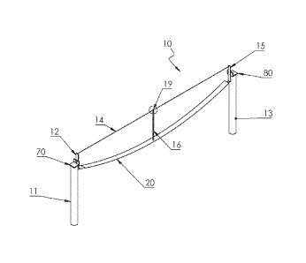
Fluid Power-Generating System Using a Single Troposkein Flexible Wing
Referring to FIGS. lA and 1B, combining a troposkein, arcuate-shaped flexible
wing 20
with a balancing system, e.g., a tensioned balancing cable 14, may provide a
particularly useful
system 10 for harvesting, i.e., generating, energy from a flowing fluid. In
some embodiments,
the embodied fluid power-generating system 10 may be disposed between and
supported by a
first elongate support 11 and a second elongate support 13 that are spaced a
distance L apart.
The distance L between supports may be estimated as a function of the maximum
wing radius,
Rinax. Typically, distances L between about 2 and about 10 times the maximum
wing radius are
suitable. Although distances larger than about 10 times the maximum wing
radius are possible,
they may result in higher tension loads that would require additional
structural and dimensional
features of the elongate supports 11, 13.
The elongate supports 11, 13 are designed to be substantially vertical and
stiff enough to
resist, without deleterious deflection towards the flexible wing, the tensile
load of the balancing
cable 14 as well as the tensile and bending loads generated while the flexible
wing 20 is being
driven by allowing fluid. The height of the elongate supports 11,13 may be
selected to
provide sufficient ground clearance, which is governed by federal and state
regulations (e.g.,
about 6 meters above ground surface in an agricultural setting), for the
flexible wing 20 when it
is rotating at a maximum wing radius, Rrnax. For example, in one
implementation, each of the
elongate supports 11, 13 may be about 10 to 12 meters high with a maximum wing
radius, Rrnax,
of about 5 to 6 meters, leaving a ground clearance of about 5 to 6 meters. For
a 12-meter tall
support 11, 13 and a 6-meter maximum wing radius, a distance between supports
of about 48 to
50 meters may be envisioned. Taller supports 11, 13 increase construction
costs as support
construction scales as a cube of the maximum wing radius, Rmax,3 rather than
as a square of the
same, Rmax,2 for other portions of construction.
Respective proximal ends of each of the balancing cable 14 and the flexible
wing 20
may be releasably attached to a first wing support 12, which may be disposed
at the first
support 11, while respective distal ends of each of the balancing cable 14 and
the flexible wing
20 may be releasably attached to a second wing support 15, which may be
disposed at the
CA 02979321 2017-09-11
WO 2016/189395 PCT/IB2016/000924
8
second support 13. For example, referring to FIG. IC, an illustrative
embodiment of a method
of releasably attaching one end of a flexible wing 20 to the first wing
support 12 is shown. As
will be discussed in greater detail below, a second tensioned cable 24 and a
third tensioned
cable 26 extend internal to and along the entire length of the flexible wing
20. In some
variations, the third cable 26, which is preferentially disposed towards the
leading edge 31 of
the flexible wing 20, may be releasably attached to a distal end of a bar 17,
e.g., by threading
the strands of the third cable 26 through an aperture 61 formed through the
distal end of the bar
17, by rolling the free-running ends of the cable strands several times around
the distal end of
the bar 17, and by weaving some of the free-running ends of the cable strands
between the
rolled turns. In some variations, the bar 17 may be a solid or a hollow
cylinder, made of metal,
an alloy, and the like, that is fixedly attached to, e.g., by welding, and
supported by the first
wing support 12. In one implementation, a portion 63 of the bar 17 may be cut
out to provide a
recessed area for receiving the first wing support 12. The second cable 24,
which is disposed
proximate the gravitational center of mass 38 of each of the airfoil-shaped
profiles 30 forming
the flexible wing 20, may be releasably attached to the bar 17, e.g., by
threading the second
cable 24 through an opening formed in the first wing support 12 and an
aperture 62 formed
through the bar 17 and attaching a retaining nut 18 to the end of the cable
24.. At the other end
of the first wing support 12, in some variations, the balancing cable 14 may
be releasably
attached to the first wing support 12 in a similar manner as the second cable
24, e.g., by
threading the second cable 24 through another opening formed in the first wing
support 12 and
attaching a retaining nut 18 to the end of the cable 24. With such an
arrangement, during
operation, the cables 26, 24 may transfer forces to the bar 17, which applies
a moment to the
first wing support 12, causing the first wing support 12 to rotate. Respective
distal ends of each
of the balancing cable 14 and the flexible wing 20 may be similarly attached
to a second wing
support 15.
At the first support 11, the first wing support 12 may be removably attached
and
operatively coupled to a machine 70 (FIG. 7A), e.g., a motor-generator (such
as a synchronous
permanent magnet (PM) motor wheel) and, in some instances, to a gearbox
associated with the
machine 70. Based on available wind, a motor-generator 70 with a gearbox may
be tuned to a
fixed frequency. Advantageously, with such a gearbox, rotation speed of the
flexible wing 20
may be fixed, which may reduce costs and simplify overall construction. The
structure and
function of the machine 70 will be described in greater detail below. At the
second support 13,
CA 02979321 2017-09-11
WO 2016/189395 PCT/IB2016/000924
9
the second wing support 15 may be removably attached and operatively coupled
to a bearing
assembly 80 (FIG. 1D). Optionally, both wing supports 12, 15 may be removably
attached and
operatively coupled to a respective machine 70. A single, asynchronous machine
70 may be
designed to operate at a fixed frequency and without an inverter, enabling the
user to couple the
machine 70 directly to a power grid. If a pair of machines 70 is used,
however, the machines
70 may have to be synchronous, e.g., to address instances in which the
machines 70 may pull
reactive power through the rotor, and may also require more complex power
conditioning
electronics, adding cost.
Referring to FIG. 1D, an illustrative embodiment of a method of releasably
attaching
the second wing support 15 to the bearing assembly 80 is shown. In some
implementations, at
the centroid of the second wing support 15, a first portion 82 may be
releasably attached to the
second wing support 15, e.g., using a nut and bolt 84. A rotatable shaft 81
may be disposed
between the first portion 82 and a second portion 83. At one of the first
portion 82 and the
second portion 83 the rotatable shaft 81 is supported by a bearing, e.g., a
series of ball bearings
in a race. At the other of the first portion 82 and the second portion 83, the
rotatable shaft 81 is
fixedly attached. As a result, rotation of the flexible wing 20 may cause the
rotatable shaft 81
to rotate within the bearing, without transferring torque from the first
portion 82 to the second
portion 83. A non-rotatable shaft 85 may be fixedly attached to the second
portion 83 for the
purpose of attaching the second portion 83 to the second support 13.
The tensioned balancing cable 14 may be manufactured of wire rope, ultra-high-
molecular-weight polyethylene fibers, steel, aramid fibers, liquid crystal
polymer fibers, and the
like and may be pre-tensioned with a tensile force that is approximately equal
to an estimated
tension force of the operating flexible wing 20. Estimated tensile force
strengths may range
between about 0.5 and 2 times the centrifugal force, depending on the length L
between
supports 11, 13. With proper material selection, this requirement may be met
automatically,
keeping in mind that, as the flexible wing 20 rotates, the wing 20 tries to
pull the inner radius
closer. This increases the tension of the balancing cable 14, which pulls back
on the flexible
wing 20. As revolution speeds of the flexible wing 20 (and balancing cable 14)
increase,
centrifugal forces and tensile forces also increase. Resonance frequencies
also may move
higher, so that they exceed the main system frequency. This minimizes unwanted
resonance, as
tensioned wing resonance remains above main motion frequencies.
In some implementations, connecting one or more rigid struts 16 or rods, which
may be
10
manufactured of hardened aluminum alloys, carbon fiber composites, high-
strength steel, and
the like, to the flexible wing 20 and to the balancing cable 14 may be
advantageous. Indeed,
connecting rigid struts 16 to the flexible wing 20 and to the balancing cable
14, inter cilia,
prevent damage to the flexible wings 20 when it twists. For example, during
operating
conditions in which the flexible wing 20 is subject to relative twisting
(torsion), the rigid struts
16 experience compression, making the system 10 more robust against torsion
and, more
specifically, preventing the flexible wing 20 from twisting beyond the
location of the struts 16.
Moreover, connecting a rigid strut(s) 16 to the flexible wing 20 and to the
balancing cable 14,
e.g., at a midpoint between the two opposing wing supports 12, 15, ensures
that the torque
transferred begins to decrease after 180 degrees of angular displacement
rather than 90 degrees.
With a rigid strut 16 installed, using a balanced cable 14 and a flexible wing
20 having a
maximum wing radius, Rinax, of about 15 meters, and assuming that the minimum
wing radius,
equals one-half of Rillax, it is possible to transfer full power torque from
one side of the
turbine system 10 to the other side at displacement angles less than 90
degrees. This effectively
.. means that distributed torque transfer from the flexible wing 20 to the
motor-generator 70
would require less angular displacement.
Those of ordinary skill in the art can appreciate the benefits and costs of
adding
additional struts 16. The first strut 16 adds the most significant improvement
to the system 10,
while each additional strut 16 adds additional improvement, but the
significance of the
improvement decreases with each additional strut 16. Disadvantageously, struts
16 also add
aerodynamic drag, weight, and cost.
FIG. 1E shows a detail of an exemplary method of attaching the rigid strut 16
to the
balancing cable 14. As shown, the rigid strut 16 and the balancing cable 14
may be
substantially perpendicular to each other; although, when more than a single
strut 16 is used,
the plural struts may be connected to the balancing cable 14 at an angle less
than about 90
degrees. Although there are a number of ways to connect a rigid strut 16 to a
cable 14, in some
implementations, the balancing cable 14 may be disposed through an opening 19
formed in the
rigid strut 16. An integrated clamp, internal to the rigid strut 16, i.e.,
within the opening 19,
may be used for securing the balancing cable 14.
FIG. IF shows a detail of an exemplary method of attaching the rigid strut 16
to the
flexible wing 20. In some embodiments, a channel 51 may be formed through the
center of the
end of the rigid strut 16, forming two opposing strut end portion 52, 53. In
some variations, the
Date Recue/Date Received 2020-05-01
CA 02979321 2017-09-11
WO 2016/189395 PCT/IB2016/000924
11
width of the channel 51 may be selected to fit, e.g., snugly, around the width
of an airfoil-
shaped profile 30. Apertures 54 may be formed in each of the strut end
portions 52, 53, while
an aperture 55 may also be formed in the airfoil-shaped profile 30 at the
aerodynamic center
39. In some implementations, a fastening device, e.g., a bolt, a rivet, and
the like may be
inserted through the apertures 54, 55. For illustrative purposes only, FIG. IF
shows a nut 57
and bolt 56 combination fastening device.
Referring to FIGS. 2A and 2B, a flexible, tensioned, troposkein wing 20 for
catching
and passing a flowing fluid and for rotating about a substantially horizontal
axis is shown.
Advantages of the instant flexible wing 20 over prior art systems include its
flexibility and
tensioning, as well as elimination of the need for a centrally disposed rotor
member in the
system 10. The tensioned flexible wing 20 may be structured and arranged with
an arcuate
shape when subjected to fluidic loading and may include a plurality of airfoil-
shaped profiles
30 (FIG. 3) that are covered by a flexible membrane 25. In some
implementations, the airfoil-
shaped profiles 30 may be fixedly attached, e.g., using glue, rivets, welding,
etc., to the
membrane 25. In some implementations, the profiles 30 are made from wood,
plastic, resins,
composites, carbon materials, and formed sheet metal. In some variations, the
airfoil-shaped
profiles 30 may be uniformly sized or be made in various incremental sizes,
e.g., smaller in at
least one dimension than an adjacent airfoil-shaped profile 30. In some
implementations, the
membrane is made of flexible fabric, canvas, carbon fiber, sailcloth, para-
aramid synthetic
fiber, high-modulus polyethylene, ultra-high-molecular-weight polyethylene,
thermoplastic
polyethylene, rice paper, tissue paper, PTFE, and liquid crystal polymers.
In some variations, the airfoil-shaped profiles 30 may have substantially the
same
dimensions, e.g., chord length, width, thickness, and the like, across the
entire length of the
flexible wing 20; however, in other variations, some of the airfoil-shaped
profiles 30, e.g., those
disposed proximate the midpoint, may have smaller dimensions than other
airfoil-shaped
profiles 30, e.g., those disposed proximate the wing supports 12, 15 where the
rotor tip speed
(TSR) is lower. For example, a Darrieus-type total chord length (TCR) for an
airfoil-shaped
profile 30 may be estimated using the following equation:
4.3 * R
T CR = ___________________________________
(TSR) 2
CA 02979321 2017-09-11
WO 2016/189395
PCT/IB2016/000924
12
in which R is the wing radius and TSR refers to the rotor tip speed, i.e., the
difference between
the linear speed of the wing and wind speed. If there are two flexible wings,
the TCR would be
halved; with three wings, the TCR would be divided by three (3), etc.
The center-to-center distance between adjacent airfoil-shaped profiles 30 may
be
substantially the same or may be varied, e.g., so that profiles 30 are closer
proximate the wing
supports 12, 15 and further apart proximate the mid-point of the flexible wing
20. Those of
ordinary skill in the art can appreciate that, in design, any number of
variations of center-to-
center spacing versus the quantity and dimensions of the airfoil-shaped
profiles 30 can be
selected to achieve substantially the same result.
Referring to FIG. 3, an illustrative embodiment of an airfoil-shaped profile
30 is shown.
Each airfoil-shaped profile 30 may include a leading edge 31, a trailing edge
33, and upper 32
and lower peripheral surfaces 37. Each airfoil-shaped profile 30 has a chord
length, an
aerodynamic center 39, and a gravitational center of mass 38. Advantageously,
at least one
opening 34, 35, 36 may be formed through each airfoil-shaped profile 30.
Corresponding
cables 28, 26, 24 may be disposed through the respective openings 34, 35, 36
formed through
each airfoil-shaped profile 30. The diameter of the openings as well as the
diameters of the
cables 28, 26, 24 may be subject to design requirements, such as close sliding
fits.
For example, a first opening 34 proximate the leading edge 31 of each airfoil-
shaped
profile 30 may be formed to accept a first, balancing weight cable 28 for the
purpose of
orienting and balancing the flexible wing 20. In some variations, the
diameters of the first
opening 34 and the first cable 28 may be larger, respectively, than the
diameters of the other
openings 35, 36 and the cables 26, 24. The balancing weight cable 28 is not
designed to
transfer any forces; hence, it remains un-tensioned and a bit relaxed. The
weight of the first
cable 28 and, hence, its diameter, may be selected to substantially match the
weight of the
airfoil-shaped profile 30. In some variations, it may be desirable to locate
the first opening 34
on an airfoil-shaped profile 30 so that a center of mass of the airfoil-shaped
profile 30, which,
as a rule of thumb, may be a distance of about 42 percent of the chord length
from the leading
edge 31, is, instead, a distance of about 25 percent of the chord length from
the leading edge
31. More particularly, it may be desirable to locate the first opening 34 on
an airfoil-shaped
profile 30 so that the center of mass of the airfoil-shaped profile 30 is
coincident with the
aerodynamic center 39 of the airfoil-shaped profile 30, which may be a
distance that is between
about 20 and about 30 percent of the chord length from the leading edge 31.
Alternatives to
CA 02979321 2017-09-11
WO 2016/189395 PCT/IB2016/000924
13
disposing a balancing weight cable 28 as described above, may include
replacing the cable 28
with a semi-rigid plate, e.g., that flexes easily in a radial direction but
that transfers loads in a
tangential direction along the flexible wing 20 to the wing supports 11, 13
and/or arranging the
airfoil-shaped profile 30 and/or ribs within the flexible wing 20 to shift the
center of mass to
the desired location, e.g., coincident with the aerodynamic center 39. The
latter alternative may
be accomplished at the time of manufacture, e.g., by injection molding of the
profiles 30. With
either alternative, the balancing weight cable 28 may also be replaced with a
light-weight, high
strength rope.
A second opening 36 may be formed at the gravitational center of mass 38 of
the airfoil-
shaped profile 30. The second opening 36 may be formed to accept a second
cable 24 for the
purpose of transferring torque to the first wing support 12. A third opening
35 may also be
formed at a location that it is substantially the same distance, i.e.,
equidistant, from the
aerodynamic center 39 of the airfoil-shaped profile 30 as the gravitational
center of mass 38,
i.e., the second opening 36. The third opening 35 may be formed to accept a
third cable 26 also
for the purpose of transferring torque to the first wing support 12. In some
implementations,
the third opening 35 may be preferentially located, e.g., preferentially
weighted, towards the
leading edge 31 of each airfoil-shaped profile 30. In some variations, the
preferential location
may be in a range of up to about three (3) percent of the chord length closer
to the leading edge
31 of each respective airfoil-shaped profile 30. In other variations, the
preferential location
may be in a range of 1 to 1.5 percent of the chord length closer to the
leading edge 31 of each
respective airfoil-shaped profile 30.
Preferential weighting may produce the following advantages: the flexible wing
20 may
flex and remain close to a zero (0) degree angle of attack and aerodynamic
momentum turns the
flexible wing 20 about the location. By balancing aerodynamic momentum with
tension forces
in the hvo cables 26, 24, which are separated by the profiles 30, it is
possible to further reduce
parasitic drag in parts of Darrieus rotor trajectories where actually no
energy is produced.
Accordingly, with such a design, it may be possible to achieve exceptional
optimization of
attack angle versus speed of rotor.
The diameters of the second 24 and third cables 26 may be approximated by
estimating
the centrifugal force and by setting the maximum tension force equal to the
product of the
centrifugal force and a variable. The variable may be about 1.2 (if the
distance between
supports is less than four (4) maximum wing radii), about 2 (if the distance
between supports is
CA 02979321 2017-09-11
WO 2016/189395 PCT/IB2016/000924
14
less than eight (8) maximum wing radii), or about 2.4 (if the distance between
supports is less
than ten (10) maximum wing radii).
Although the embodiment has been described in terms of two cables 26, 24 for
transferring torque, those of ordinary skill in the art can appreciate that
torque transfer may also
.. be accomplished using a single cable. However, the advantages of using two
cables 26, 24,
which may include greater stability and balancing, may outweigh the advantages
of a single
cable embodiment.
Although the cables 28, 26, 24 can be steel wires, if larger flexible wings 20
are desired,
to reduce weight, cables 26 and 24 may be manufactured from, for example,
light-weight ultra-
high-weight polyethylene fibers, while only the frontal cable 28 may be made
of steel to act as
ballast. It is important to note that, when rigid blades are used in other
applications, it is
problematic to achieve stable wing performance within different operating
conditions without
adding ballast. Indeed, without balancing the wings 20, e.g., using the
frontal cable 28, the
system 10 may suffer and tend to increase attack angles in a manner contrary
to resisting its
.. motions.
An alternative embodiment of an airfoil-shaped profile 40 is shown in FIGS. 4A
and
4B. Each alternative airfoil-shaped profile 40 includes a leading edge 41, a
trailing edge 43,
and upper 42 and lower peripheral surfaces 47. Whereas the first embodiment of
an airfoil-
shaped profile 30 (FIG. 3) may include a plurality of openings 34, 35, 36 for
a corresponding
plurality of cables 28, 26, 24, the alternative airfoil-shaped profile 40 may
have a single
opening 44 that may be disposed at the leading edge 41. Such an alternative
may be more
difficult to balance as balancing the tension in the membrane 25 with the
tension of the single
cable, each of which may be made from a different material, is a difficult
task. Furthelmore,
such an alternative embodiment may result in a lighter structure, which is not
necessarily
beneficial. For example, if the mass of the flexible wing 20 is too light, the
wind may move the
flexible wing 20 around so that it does not follow the optimum trajectory for
extracting power.
For example, a rule-of-thumb, minimum weight for the flexible wing 20 may be
about 0.13R2
(in kg per linear meter of wing).
To reduce the weight of the flexible wing 40 further, each alternative airfoil-
shaped
profile 40 may be structured and arranged similar to a truss (FIG. 4B), in
which there are load-
carrying members 45 as well as cut-out section 46. Those of ordinary skill in
the art can
appreciate that the airfoil-shaped profile 30 may also be designed using a
truss concept. Here
CA 02979321 2017-09-11
WO 2016/189395 PCT/IB2016/000924
again, such an embodiment may result in a lighter structure and, consequently,
if the mass of
the flexible wing 20 is too light, the wind may move the flexible wing 20
around so that it does
not follow the optimum trajectory for extracting power.
5 Multiple-Wing Power-Generating System
Some benefits of a single, flexible wing system 10 with a balancing cable 14
include
that it can be fully stopped and that the mass of the wing is greater than the
mass of remainder
of the system 10 structure. Advantageously, when completely stopped and not
operating, the
single, flexible wing system 10 may withstand significant wind gusts, e.g., 70
meters/second,
10 that other structures comprising similar material could not. For
locations in which significant
wind gusts are not or less of a concern and/or where a preferred condition may
include a
symmetric look, less vibrations, and/or less torque ripple, one or more
additional flexible wings
may be added. Advantageously, a second flexible wing may replace the balancing
cable 14.
Referring to FIGS. 5A and 5B, an illustrative embodiment of a dual-wing system
50 is
15 shown. Such a system 50, having two opposing flexible wings 20a, 20b,
may form a
symmetrical and substantially balanced structure. Although a three-wing system
may provide
even smoother motion and better balance than the dual-wing version 50, such
advantages and
benefits come at the expense of increased structure complexity and cost. The
number of rigid
struts 16a-16c, each of which increases aerodynamic resistance, for a multi-
wing system 50
may be more than one, depending on design targets. Notwithstanding, three
rigid struts 16a-
16c, equally spaced (L/4) between the supports 11, 13, provide an effective
and efficient system
50. The designer, however, may choose to allow some bending (with fewer
struts) to achieve
even smoother wing movement and less torque oscillation. In comparison to
horizontal axis
bladed-systems, the multi-wing system 50 may increase the swept area 3 to 4
times, providing
more power and, advantageously, operating at wind speeds that otherwise would
be outside of
the operation range of propeller-driven wind turbines.
The design and structure of the flexible wings 20a, 20b of multi-wing system
50, as
well as the design and structure of the connection between the flexible wings
20a, 20b and the
rigid struts 16a-16c and the design and structure of the connection between
the flexible wings
20a, 20b and the wing supports 12, 15, may be substantially similar to those
previously
described in connection with the flexible wing and balancing cable embodiment
10. A primary
difference between the two systems 10, 50 may be the number of rigid struts
16.
CA 02979321 2017-09-11
WO 2016/189395 PCT/IB2016/000924
16
In yet another embodiment, referring to FIGS. 8A through 8C, a power-
generating
system 90 having two pairs of half wings 20c, 20d and 20e, 20f, whose distal
ends are attached
to a cross strut 23, e.g., a T-shaped cross strut, and which are skewed 90
degrees at midlength
(L/2), is shown. The cross strut 23 and skewing the pairs of half wings 20c,
20d and 20e, 20f
reduce vibrations and bending moments at the supports 11, 13 as, with every
rotation, torsional
forces are distributed better, reducing torque ripple. Although a skewing
angle of 90 degrees is
described, those of ordinary skill in the art can appreciate that, in other
implementations, the
system 90 may include more than two pairs of half wings, with a cross strut
structured and
arranged to be attached to the distal ends of each of the flexible wings in
each of the pairs and
an appropriate skewing angle.
In some variations, the third cable 26 of each of the multiple half wings 20c,
20d, 20e,
20f may be releasably attached to a distal end of one of the rods making up
the cross strut 23,
e.g., by threading the strands of the third cable 26 through an aperture
formed through the distal
end of the respective rod, by rolling the free-running ends of the cable
strands several times
around the distal end of the respective rod, and by weaving some of the free-
running ends of
the cable strands between the rolled turns. The second cable 24, which is
disposed at the
gravitational center of mass 38 of each of the airfoil-shaped profiles 30
forming each half wing
20c, 20d, 20e, 20f, may be releasably attached to the respective rod of the
cross strut 23, e.g.,
by threading the second cable 24 through an aperture 62 formed through the
respective rod of
the cross strut 23 and attaching a retaining nut 18 to the end of the cable
24.
Operation
Operation of the flexible wing and balancing cable system 10 of FIG. lA and of
the
dual-wing system of FIG. 5A and a method of generating power with the systems
10, 50 will
now be described. An illustrative, hybrid power-generating system 60 shows the
major
structural elements of the two systems 10, 50 and will be referred to in this
description.
Recall that each flexible wing 20 of the embodied systems 60 is supported at a
distal
and proximal end by a first 11 and a second support 13 and that each wing 20
may include
plural, e.g., three (3), cables 28, 26, 24, of which, one, un-tensioned cable
28 may be provided
for the purpose of balancing the light-weight structure and at least one,
tensioned cable 26, 24
may be used to actually transfer force to a machine 70. In some variations,
the second cable 24
may be disposed proximate the gravitational center of mass 39 of each of the
airfoil-shaped
CA 02979321 2017-09-11
WO 2016/189395
PCT/IB2016/000924
17
profiles 30, which provide structure and a load-carrying capability to the
flexible wing(s) 20.
When two cables 26, 24 are used, their midpoint may be proximate the
aerodynamic center 39
of each of the airfoil-shaped profiles 30. However, the distance between cable
26 and the
aerodynamic center 39 of each of the airfoil-shaped profiles 30 may be
preferentially weighted
towards the leading end 31 of the airfoil-shaped profile 30.
The membrane 25 may be fixedly attached to each of the airfoil-shaped profiles
30 to
form the flexible wing 20. Advantageously, a portion of the cable 26, 24 may
also pretension
the membrane 25, enabling the membrane 25 to maintain an aerodynamic shape,
especially in
places where there are no airfoil-shaped profiles 30. Some important
properties of a flexible
wing 20 may include radial flexibility, i.e., when coupled to a machine 70,
and greater rigidity
when bent tangentially.
In some embodiments, in a first step, the method includes providing a machine
70
capable of acting as a motor and as a generator on the first support 11. In
some
implementations, in a next step, the distal ends of each tensioned cable(s)
26, 24 disposed
within the flexible wing(s) 20, may be releasably attached to a first wing
support 12, while the
proximal ends of each tensioned cable(s) 26, 24 disposed within the flexible
wing(s) 20, may
be releasably attached to a second wing support 15. Attachment of the
respective ends of the
cables 26, 24 to wing supports 12, 15 has been discussed previously and will
not be discussed
further. Similarly, attachment of the second wing support 12 to the bearing
assembly 80 at the
second support 13 has already been discussed in detail.
As for attaching the first wing support 12 to the machine 70, FIGS. 7A and 7B
show an
illustrative embodiment for operatively coupling the first wing support 12 to
a synchronous PM
motor wheel or machine 70. Those of ordinary skill in the art can appreciate
that selecting a
synchronous PM motor wheel as the machine 70 is for illustrative purposes only
and the
invention is not to be construed as being limited thereto. Indeed, other motor-
generator
machine types may be used and all are within the scope of the present
invention.
The synchronous PM motor wheel (machine 70) is a synchronous motor that uses a
magnetic field created by a plurality of permanent magnets, e.g., disposed on
an annular ring
79, held by braces 72. A slip ring 75 may be provided, e.g., between the
armature 71 and a
rotor arm 78, for adjusting resistance for allowing free rotation of the rotor
78 with windings
and decoupling rotating windings from the stationary power cable 73. A power
cable 73 may
be provided to transmit the induced electricity to a load, to a power grid,
and/or to a power-
CA 02979321 2017-09-11
WO 2016/189395 PCT/IB2016/000924
18
storage device. The workings of the machine 70 may be housed in and supported
by an annular
ring 79 that is supported by a number of braces 72.
The aforementioned rotor arm 78 may be releasably attached to the first wing
support
12, e.g., via an opening located at a centroid of the wing support 12 and/or
at a midpoint
between the points of attachment of the cable ends, using a fastening device
77, e.g., bolts. In
some implementations, the rotor arm 78 is coupled to the armature 71, e.g.,
via the slip ring 75,
so that when the rotor arm 78 is made to rotate by the rotating first wing
support 12, the
armature 71 does not rotate. The changing magnetic field generated by the
plurality of
permanent magnets, induces current, generating power.
In a next step, the flexible wings 20 may be exposed to the flowing fluid to
drive the
machine 70. As the wings 20 rotate, in some variations, the method may include
orienting
and/or balancing the flexible wings 20, e.g., by disposing a balancing cable
28 through an
aperture 34 proximate a leading edge 31 of each airfoil-shaped profile 30 in
the flexible wings
20, and transferring torque to the machine, e.g., using the cables 26, 24
disposed through
respective apertures 35, 36 in each airfoil-shaped profile 30. At least one
rigid strut 16
disposed between the flexible wings 20 supports the flexible wings and
stabilizes the system.
In low ambient flow conditions, the machine 70 can be operated briefly as a
motor, to bring the
system 60 up to a minimum rotational speed, after which the wings 20 are
sufficiently flexed
and loaded, that rotation is sustained by the ambient flow and the machine 70
may be switched
to operate as a generator.
Physics and Design Parameters
Systems with flexible wings and balanced cables may behave similarly to a
single wire
connecting two wheels. As previously mentioned, torque transfer for a single
tensioned wire
can be approximated as (H/L)*R2*sin(a). In this approximation the horizontal
tension force
(H) may be assumed to be constant in certain fixed operating conditions, which
is not always
true, e.g., due to cable elongation and different loads. At small displacement
angles, e.g., less
than or equal to about 30 degrees, however, the assumption is more correct as
H is almost
constant for selected angular velocities, wind speeds, and rotor positions,
and mostly dominated
by pretension and/or centrifugal forces. To estimate required strength it may
be useful to use
the maximum force that appears when wing is perpendicular to wind flow.
By coupling a rigid strut to the span centers of the flexible wing and of the
balancing
CA 02979321 2017-09-11
WO 2016/189395
PCT/IB2016/000924
19
cable, transferred torque from one side to another may be approximated by the
equation:
Torque = H/L* R2 *sin(ct/2).
A Darrieus blade may operate well in a radius range at which the speed of
blade is at
least 2.5 times the rotor tip speed. However, high drag may be produced at
extreme angles of
attack, which may be estimated using the following equation:
Angle of Attack = arctan[sin((p)/(i, + cos((p))J,
in which where k is tip speed ratio. Accordingly, in extreme instances, i.e.,
when 9 = 90
degrees, the angle of attack may equal arctan11/k1.
For a flexible wing, the maximum wing radius, Rim, may operate at 4.5 to 5
times the
tip speed ratio, with the minimum wing radius, Rmin, equal to about Rffiax/2.
Although, in some
applications, Rmin may be less than about Rina1/2, e.g., Rinin may instead
equal about Rmax/3 ,
because the flexible wing does not produce any power, only drag, until it
reaches at least Rinin.
Fixing Rim, = Rmax/2 may be conservative.
The design length of the flexible wings may be influenced by a tradeoff
between swept
area, torque transfer, and the ratio of tension force versus centrifugal
force. For example, it
may be desirable to assume a tension force that is about 1.2 times larger than
centrifugal force.
Using this relationship for a tension force 1.2 times larger than centrifugal
force, the design
length (L) may be estimated using the following equation:
L = 10*(Rmax¨ Rim) =I 0* ¨ Rmax/2) = 5* Rmax,
which provides a good material use for the cables but a relatively small swept
area. At the high
end, e.g., where tension force may be about 2.4 times the centrifugal force
(e.g., due to alight-
weight blade), the design length (L) may be estimated using the following
equation:
L ¨ 20* (Rmax Rmin) ¨ 2 0* (Rmax Rmax/2) ¨ 1 0*Rmax.
If the tension force may be about 2 times the centrifugal force, the design
length (L) may be
CA 02979321 2017-09-11
WO 2016/189395
PCT/IB2016/000924
estimated using the following equation:
L = 16*(Rmax¨ Rimn) = 16*(Rma. Rma1/2) = Mina,
5 Assuming L/Rmm, = 8, i.e., tension force equals twice the centrifugal
force, the formulae
for torque transfer become:
Torque Transfer = H*Rmax*sin(c.a2)/8 (with a central rigid strut) or
10 Torque Transfer = H*Rmax*sin(a/2)/32 (without a central rigid strut).
Simplifying the equations using the small-angle approximation, i.e., sin(a/2)
is approximately
equal to a/2 (in radians), one may conclude that adding a central rigid strut
increases torque
transfer capability by a factor of four for the same displacement angle.
Hence, the system may
15 .. become more efficient by adding a single rigid strut. Additional rigid
struts (beyond one) add
weight, cost, and aerodynamic drag, while making torque transfer slightly more
efficient.
In order to estimate the magnitude of power that can be transferred via such a
system,
centrifugal force (Fe) may be estimated using the equation:
20 F = 5/6*m*102*Rmaõ,
in which co is a rotational speed (in radians/second) and m is mass (in kg).
The constant 5/6
corresponds to a parabolic approximation of the offset of the center of mass
when Rmin =
Rmax/2. Accordingly, tension force (H) may be calculated using the equation:
H = 2*F, = 5/3 *m*032*Rmax.
Accordingly, power transferred (P) may be estimated using the equation:
P1 > (0*H*Rmax*sin(11/2)/8 = 5/24*m*o)3*Rmax2*sin(a/2).
Limitations of rotational speed, a), may be given in terms of 2. (i.e., tip
speed ratio), and
CA 02979321 2017-09-11
WO 2016/189395
PCT/IB2016/000924
21
external wind speed, v, using the definition:
= oo*Riv.
For a Darrieus-type turbine, one of best rotor solidity ratios, i.e. chord
length to Rmax,
for a single wing is approximately 0.21 (e.g., for NACA-0012 family of
profiles) and an
optimal tip speed ratio (2) is in the range of 4 (worst case) to 5 (best
case). Substituting the
worst case tip speed ratio into the above equation, co = 4*v/Rina1.
Substituting this angular
velocity into the power equation above results in:
Pi 1-40/(3*Rma,)1* m*v3*sin(ct/2),
corresponding to the power transferred from one wing support to another one.
If power is
sourced and distributed evenly on each wing of a dual-wing system, the
generated power may
be roughly twice that amount, i.e., 2P1.
Assuming that the shape of the path of the flexible wing may be approximated
by a
parabola, the swept area may be calculated using the equation:
Swept Area = 2/3*L*(2*Rmax+ Rifiin).
For Rima= Rmax/2 and L = 8*Rmax,
Swept Area = 40/3*Rmax2.
The maximum power extracted by turbine may be estimated using the equation:
13/ = 1.225*0.5*0.4*v3*(40/3*Rmax2)
in which v is wind speed, 11.225 is an air density at sea level, 0.4 is a
coefficient of efficiency,
and 0.5 is a coefficient derived from the kinetic energy relationship.
Equating 2P1 to P2,
2140/(3*Rma1)]* m*v3*sin(a/2) = 1.225*0.5*0.4*v3*(40/3*Rmax2), or
CA 02979321 2017-09-11
WO 2016/189395
PCT/IB2016/000924
22
2*m*sin(a/2) = 1.225*0.5*0.4* Rmax3,
which suggests that, at a given angle of displacement (a), transferred power
may depend on the
selected radius and mass, but not on wind speed (v). This allows a designer,
especially in a
multi-bladed configuration, to select a displacement angle (a) to ensure
stability and generate
smooth torque, e.g., as is possible with Gorlov's turbines and quiet
revolution turbines, without
having to design for a particular wind speed.
Thus, the minimal mass required to transfer torque for a given displacement
angle may
be determined by the general equation:
m = 0.1225*Rinax3/sin(a/2).
Recalling that, for maintaining the centrifugal force higher than aerodynamic
force, the mass
per length of wing is equal to 0.13*Rx2. Hence, for a wing length of 8*Rmax:
m = (8*Rmax)* 0. 1 3*Rmax2 = 1 .04*Rmax3.
Setting these two equations equal to one another and solving for the
displacement angle (a), a
is approximately equal to 13.5 degrees.
Accordingly, for a 6-meter maximum wing radius, the mass of the flexible wing
may weigh
about 225-kg and the length may be about 48 meters, which may produce tension
forces of
approximately 16 kN at a wind speed of 4 meters/second (m/s) and of about 100
kN at a wind
speed of about 10 m/s, assuming, of course that the tip speed ratio is
maintained.
With a flexible wing and balancing cable combination, tension forces produced
at the
supports may be doubled, e.g., because the balancing cable would resist
stretching. However,
allowing the displacement angle to increase allows the mass to decrease and,
consequently,
tension forces. A common pitfall to designers includes aerodynamic balance and
gusts. For
example, flexible wings must maintain their trajectory against gusts, which
may impose some
limitations on possible mass reduction. A mass limitation of 0.13*Riffax2 per
length of wing
maintains wing trajectory only at nominal speeds, not with gusting.
CA 02979321 2017-09-11
WO 2016/189395 PCT/IB2016/000924
23
A table of select design parameters and exemplary values or ranges is provided
in FIG.
9.
Comparison to Darrieus-type Vertical Axis Wind Turbines and Propeller-type
Horizontal Axis
Wind Turbines
The system described herein may significantly outperform previously known
Darrieus-
type vertical axis wind turbine in terms of material costs. It is also widely
known that a
propeller- type design, especially for large swept areas, may outperform
vertical axis wind
turbines. An exception being certain niche devices, whose specific performance
requires
capturing wind from all directions, e.g., on roofs in urban locations.
Using the same assumptions, i.e., Rmin= Rmax/2 and L = Min, the swept area may
be
approximately I 3.3*Rmax.2 Thus, a propeller-type turbine with an equivalent
swept area may
require a radius equal to the square root of 13.3/ rt. Hence, a comparable
radius for a propeller
may be roughly twice as large as the flexible wing or, the same radius, may
require four
.. propellers instead of a single flexible wing.
Because these propellers capture most of their energy at the perimeter of
their rotation,
rather than in a central line at the top of the supports, the propeller may be
moved higher and,
thus, the support must be taller. If we compare this design of a 6-meter Rffax
radius on a 12-
meter support, to get an equivalent result with two propellers on two supports
their radii should
be about 8.5 meters. Furthermore, the height of the support may range between
about 15
meters (to provide a 6 meter clearance in an agricultural setting) and about
18 meters (to
maintain a 9-meter stand-off where wind energy harvesting starts). In the case
of a single
propeller blade, the blade length may need to be about 12 meters in length and
the support
height may range between about 18 and 21 meters to maintain acceptable
clearances and
efficiencies.
Construction of the supports may scale closer to the square of their height
and the cube
of radii of the rotor. Hence, taller support requirements may increase support
costs by between
1.3 and 1.8 times, depending also on a log wind profile. For example, in
terrains where an
exemplary wind is considerably slower at 10 meters above the ground surface
than at 20
meters, e.g., terrain having high surface roughness, a greater height for the
propeller and a taller
support may be more beneficial.
Propeller blades are complex, as these should be rigid elongate structures
that resist
CA 02979321 2017-09-11
WO 2016/189395
PCT/IB2016/000924
24
buckling and bending. Practical 3-bladed propellers with 12-meter blades may
have a tip speed
ratio of about 7. The weight of a single blade may be about 750 kg, e.g.,
using advanced
composite materials. Thus, the total weight would be about 2.2 metric (or
long) tonnes for the
entire rotor. Compared to the weight and costs for a flexible wing of 225 kg,
the weight of the
latter is negligible. Moreover, support design and design for a rotor must
take into account the
more significant blade weight. Flexible wings according to the invention may
also be rolled
into a compact configuration for ease of transport and installation. This is
clearly not the case
for rigid propellers and other rigid wings, that require unitary construction
or, in some cases,
multiple linked elements, adding weight and cost.
The terms and expressions employed herein are used as terms and expressions of
description and not of limitation, and there is no intention, in the use of
such terms and
expressions, of excluding any equivalents of the features shown and described
or portions
thereof In addition, having described certain embodiments of the invention, it
will be apparent
to those of ordinary skill in the art that other embodiments incorporating the
concepts disclosed
herein may be used without departing from the spirit and scope of the
invention. The features
and functions of the various embodiments may be arranged in various
combinations and
permutations, and all are considered to be within the scope of the disclosed
invention.
Accordingly, the described embodiments are to be considered in all respects as
only illustrative
and not restrictive. Furthermore, the configurations, materials, and
dimensions described
herein are intended as illustrative and in no way limiting. Similarly,
although physical
explanations have been provided for explanatory purposes, there is no intent
to be bound by
any particular theory or mechanism, or to limit the claims in accordance
therewith.