Language selection

Search

Patent 2979572 Summary

Third-party information liability

Some of the information on this Web page has been provided by external sources. The Government of Canada is not responsible for the accuracy, reliability or currency of the information supplied by external sources. Users wishing to rely upon this information should consult directly with the source of the information. Content provided by external sources is not subject to official languages, privacy and accessibility requirements.

Claims and Abstract availability

Any discrepancies in the text and image of the Claims and Abstract are due to differing posting times. Text of the Claims and Abstract are posted:

  • At the time the application is open to public inspection;
  • At the time of issue of the patent (grant).
(12) Patent: (11) CA 2979572
(54) English Title: TRACK HEAD AND TRACK LAMP
(54) French Title: TETE DE RAIL ET LAMPE DE RAIL
Status: Granted
Bibliographic Data
(51) International Patent Classification (IPC):
  • F21V 19/00 (2006.01)
(72) Inventors :
  • LI, LI (China)
  • SONG, GANG (China)
(73) Owners :
  • JIAWEI RENEWABLE ENERGY CO., LTD. (China)
(71) Applicants :
  • SHENZHEN JIAWEI PHOTOVOLTAIC LIGHTING CO., LTD. (China)
(74) Agent: BROUILLETTE LEGAL INC.
(74) Associate agent:
(45) Issued: 2019-07-23
(86) PCT Filing Date: 2016-03-10
(87) Open to Public Inspection: 2016-09-22
Examination requested: 2017-09-13
Availability of licence: N/A
(25) Language of filing: English

Patent Cooperation Treaty (PCT): Yes
(86) PCT Filing Number: PCT/CN2016/076059
(87) International Publication Number: WO2016/146018
(85) National Entry: 2017-09-13

(30) Application Priority Data:
Application No. Country/Territory Date
201520146619.3 China 2015-03-13

Abstracts

English Abstract


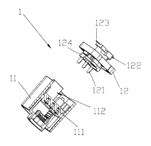
The present application relates to the technical field of luminaire, and
provides a track head (1)
for mounting a lamp body (21) on a track strip, the lamp body (21) comprises a
mounting rack (22),
the track head (1) comprises a cassette body (11) fixed to the mounting rack
(22) and a cover body
(12) movably mounted on the track strip, the cover body (12) is detachably
mounted on the cassette
body (11), a plurality of first resilient sheets (111) which are electrically
connected to the lamp
body (21) are provided in the inner part of the cassette body (11), a
plurality of second resilient
sheets (121) which are electrically connected to the first resilient sheets
(111) respectively are
provided in the inner side of the cover body (12), a conductive structure is
provided between the
cover body (12) and the track strip for electrical interconnection with each
other. The track head
(1) of the present application has a cassette body (11) fixed and electrically
connected to the lamp
body (21), the cover body (12) adapted to the track strip which can be
selected and mounted to the
cassette body (11), and the second resilient sheets (121) are abutting against
and electrically
connected to the first resilient sheets (111), and the cover body (12) is
mounted in the track strip so
as to fix the lamp body (21) to the track strip, so that the selection of the
lamp body (21) is not
restricted by the structure of the track strip and the installation and
maintenance costs are reduced.


French Abstract

L'invention concerne une tête (1) de rail utilisée pour le montage d'un corps de lampe (21) sur un segment de rail. Le corps de lampe (21) comprend un bâti de montage (22), la tête (1) de rail comprend un corps de boîtier (11) utilisé pour être fixé sur le bâti de montage (22) et un corps de couvercle (12) utilisé pour être monté de manière amovible sur le segment de rail, le corps de couvercle (12) est monté sur le corps de boîtier (11) de manière détachable, une pluralité de premières feuilles élastiques (111) utilisées pour être connectées électriquement au corps de lampe (21) sont prévues dans une partie interne du corps de boîtier (11), un côté interne du corps de couvercle (12) est pourvu d'une pluralité de secondes feuilles élastiques (121) utilisées pour entrer en contact de manière correspondante avec la totalité des premières feuilles élastiques (111) et pour être conductrices avec celles-ci et des structures conductrices utilisées pour être conductrices entre elles sont prévues entre le corps de couvercle (12) et le segment de rail. Le corps de boîtier (11) de la tête (1) de rail est connecté électriquement et à demeure au corps de lampe (21) et le corps de couvercle (12) qui a la possibilité d'être adapté au segment de rail est monté sur le corps de boîtier (11), la connexion électrique est réalisée au moyen des premières feuilles élastiques (111) venant en butée contre les secondes feuilles élastiques (121), puis le corps de couvercle (12) est monté dans le segment de rail, de telle sorte que le corps de lampe (21) soit fixé au segment de rail et que le corps de lampe (21) ne soit pas limité par la structure du segment de rail, ce qui permet de réduire les coûts de montage et d'entretien.

Claims

Note: Claims are shown in the official language in which they were submitted.


CLAIMS
1. A track head is configured for mounting a lamp body on a track strip,
wherein the
lamp body comprises a mounting rack, the track head comprises a cassette body
fixed
to the mounting rack and a cover body movably mounted on the track strip, the
cover
body is detachably mounted on the cassette body, a plurality of first
resilient sheets
for electric connection of the lamp body are provided in the cassette body, a
plurality
of second resilient sheets for corresponding contact and conduction of the
first
resilient sheets are provided on the inner side of the cover body, and a
conductive
structure for electrical interconnection with each other is provided between
the cover
body and the track strip, wherein the first resilient sheets are bent at the
ends into an
inclined structure that facilitates insertion of the second resilient sheets.
2. The track head of claim 1, wherein the conducive structure comprises a
plurality of
contacts provided in the track strip and a plurality of third resilient sheets
provided on
the outside of the cover body, wherein each of the third resilient sheets are
electrically
connected to the second resilient sheet correspondingly.
3. The track head of claim 2, wherein the cover body is provided with a stop
lug for
engagement into the track strip.
4. The track head of claim 3, wherein the third resilient sheets extends
outwardly
along the stop lug.
5. The track head of claim 4, wherein the lamp body has three wires of an L
wire, an
N wire, and a ground wire, and the number of the first resilient sheets, the
second
resilient sheets, and the third resilient sheets are all respectively numbered
three.
6. The track head of claim 4, wherein the cover body is bolted to the cassette
body.
7. The track head of any one of claims 1 to 6, wherein the cassette body is
provided
with a mounting cavity with its upper end open and with the first resilient
sheets
being arranged at its lower end side by side, the cover body is provided with
a
8

mounting portion for inserting and fitting into the mounting cavity, and the
second
resilient sheets are arranged at the outer end of the mounting portion side by
side.
8. The track head of claim 7, wherein the lower end of the mounting cavity is
provided with a plurality of slots for the insertion of the second resilient
sheets, and
the first resilient sheets are disposed in the slots.
9. A track lamp comprising the lamp body and the track head according to any
one of
claims 1 to 8.
9

Description

Note: Descriptions are shown in the official language in which they were submitted.


CA 02979572 2017-09-13
TRACK HEAD AND TRACK LAMP
TECHNICAL FIELD
The present application relates to the technical field of lamps, and more
particularly relates to
a track head and track lamp.
BACKGROUND
A track lamp is a kind of common lamp, its lamp body can be moved along its
track strip to
change the position to suit the needs of the lighting. In a track lamp in the
prior art, a lamp body is
fixed with a track head, and a corresponding track strip should be fitted in
the assembly and use,
and in the assembly of a variety of new track lamps or the replacement of old
track lamps, due to
the track strip corresponding to the structure of the track head, the
selectivity of the lamp body will
be limited, and cost in the assembly and maintenance is increased.
SUMMARY OF THE INVENTION
One object of the present application is to provide a track head and track
lamp which can
overcome the problem of the prior art that the track strip must correspond to
the lamp structure
with a limitation in the selectivity of the lamp body and high cost in the
installation and
maintenance.
The present application is realized as follows: a track head is configured for
mounting a lamp
body on a track strip, the lamp body comprises a mounting rack, the track head
comprises a cassette
body fixed to the mounting rack and a cover body movably mounted on the track
strip, the cover
body is detachably mounted on the cassette body, a plurality of first
resilient sheets for electric
connection of the lamp body are provided in the cassette body, a plurality of
second resilient sheets
for corresponding contact and conduction of the first resilient sheets are
provided on the inner side
1

CA 02979572 2017-09-13
of the cover body, and a conductive structure for electrical interconnection
with each other is
provided between the cover body and the track strip.
Furthermore, the conducive structure comprises a plurality of contacts
provided in the track
strip and a plurality of third resilient sheets provided on the outside of the
cover body, wherein each
of the third resilient sheets are electrically connected to the second
resilient sheet correspondingly.
Furthermore, the cover body is provided with a stop lug for engagement into
the track strip.
Furthermore, the third resilient sheets extends outwardly along the stop lug.
Furthermore, the lamp body has three wires of an L wire, an N wire, and a
ground wire, the
first resilient sheets, the second resilient sheets, and the third resilient
sheets are respectively
numbered three correspondingly.
Furthermore, the cover body is bolted to the cassette body.
Furthermore, the cassette body is provided with a mounting cavity with its
upper end open
and with the first resilient sheets being arranged at its lower end side by
side, the cover body is
provided with a mounting portion for inserting and fitting into the mounting
cavity, and the second
resilient sheets are arranged at the outer end of the mounting portion side by
side.
Furthermore, the lower end of the mounting cavity is provided with a plurality
of slots for the
insertion of the second resilient sheets, and the first resilient sheets are
disposed in the slots.
Furthermore, the first resilient sheets are bent at the ends into an inclined
structure that
facilitates insertion of the second resilient sheets.
Compared with the prior art, the track head of the present application has a
cassette body fixed
to the lamp body and a replaceable cover body where the adapted cassette body
can be selected for
the track strip. After the cassette body and the lamp body are fixed, the
first resilient sheets are
electrically connected with the lamp body, and the second resilient sheets on
the inside of the cover
body are abutting against and electrically connected to the first resilient
sheets, and are further
electrically connected to the track strip by an external conductive structure
so as to finally
electrically connect and fix the lamp body to the track strip. It is only
needed to replace the cover
2

CA 02979572 2017-09-13
body and mount the cover body to the cassette body when the lamp body or the
track strip need be
replaced, the selection range of the lamp body is not limited, and the cost of
assembly and
maintenance is low.
The present application further provides a track lamp, which comprises a lamp
body and the
aforesaid track head. The lamp body of the present application is directly
fixed with and electrically
connected to the cassette body at the factory, and according to different
track strips, selecting
different cover bodies can achieve the assembly, with greater adaptability and
lower cost of use
and maintenance.
BRIEF DESCRIPTION OF THE DRAWINGS
Fig.1 shows an overall structural schematic view of a track lamp according to
one embodiment
of the present application.
Fig.2 shows a partially cross-sectional assembled schematic view of a track
head according to
one embodiment of the present application.
Fig.3 shows a partially cross-sectional schematic view of a track head
according to one
embodiment of the present application.
Fig.4 shows a schematic view of a cover body in another structure according to
one
embodiment of the present application.
DETAILED DESCRIPTION OF THE EMBODIMENT
In order to make the purposes, technical solutions, and advantages of the
present application
clearer and more understandable, the present application will be further
described in detail
hereinafter with reference to the accompanying drawings and embodiments. It
should be
understood that the embodiments described herein are only intended to
illustrate but not to limit
the present application.
3

CA 02979572 2017-09-13
Example embodiments of the present application will now be described more
fully hereinafter
with reference to the accompanying drawings.
The track head 1 of this embodiment can fix the lamp body 21 with the track
strip (no show).
As shown in Figs.1 to 3, the lamp body 21 comprises a mounting rack 22 and an
inner circuit
structure, and the circuit is provided with a corresponding wire 23
electrically connected to the
outside. The track head 1 comprises a cassette body 11 and a cover body 12
which are independent
of each other, and the cover body 12 is detachably mounted on the cassette
body 11.
The cassette body 11 may fixed to the mounting rack 22, and a plurality of
first resilient sheets
111 are disposed in the cassette body 11, the lamp 11 can be connected to the
power supply through
the cassette body 11 when the wires 23 of the lamp body 21 are electrically
connected to the first
resilient sheets 111.
The cover 12 can be mounted in the track strip, a second resilient sheets 121
is provided on
the inside of the cover body 12, and a conductive structure is provided
between the track strip and
the cover body 12. The conductive structure can be designed according to the
different track strips.
The cover body 12 is mounted in the track strip and is electrically connected
to the track strip, and
then the cassette body 11 is mounted together with the cover body 12, at this
time, the second
resilient sheets 121 is electrically connected with the first resilient sheets
111 so that the lamp 21
is electrically connected to the track strip and fixed by the track head 1.
With the track head 1 of this embodiment, it is possible to design the
different cover bodies
12 according to the different track strips in advance, the appropriate cover
body 12 is selected
during the assembly, the cassette body 11 is fixed to the lamp body 21, and
then the cover body 12
adapted to the track strip is selected to be fixed with the cassette body 11,
the cover body 12 is
fixed to the track strip, and an electrically connection between them is
ensured, so that the assembly
process is completed. The replacement is easier, because the cassette body 11
is detachably fixed
to the cover body 12 and is electrically connected by the resilient sheets. It
is possible to optionally
select a suitable lamp body and thereby enlarge the selection range of the
lamp body 21, regardless
4

CA 02979572 2017-09-13
of the influence of the structure of the track strip, whether the new lamp
body 21 is installed or the
old lamp body 21 is replaced; moreover, the cost of adaptation to the track
strip is changed from
changing the entire lamp body 21 to changing the cover body 12, thereby
ultimately reducing the
cost of installation and post-maintenance.
The cassette body 11 and the cover body 12 can be fixed in a variety of ways,
such as magnetic
pole adsorption, engagement of the card block and the card slot. In this
embodiment, the cover
body 12 is bolted to the cassette body 11 that the installation and removal
can be achieved by just
rotating the corresponding bolts.
As showed in Fig. 2 and Fig. 3, the cassette body 11 is provided with a
mounting cavity 112
with its upper end open and with the first resilient sheets 111 being arranged
at its lower end side
by side. The cover body 12 is provided with a mounting portion 124 for
inserting and fitting into
the mounting cavity 112 for mating with the mounting process, and the second
resilient sheets 121
are arranged at the outer end of the mounting portion 124 side by side. The
cassette body 11 and
the cover body 12 constitute a plug structure which can be fixed and
electrically connected directly
by plugging.
A plurality of slots for insertion of the second resilient sheets 121 are
provided at the lower
end of the mounting cavity 112, and the first resilient sheets 111 are
disposed in the slots. The
second resilient sheets 121 are inserted into the slots and connected with
first resilient sheets 111
when insertion and connection of the cassette body 11 and the cover body 12
have been completed,
and the first resilient sheets 111 are bent at the ends into an inclined
structure that facilitates the
connection between the second resilient sheets 121 and the first resilient
sheets 111 after the
insertion of the second resilient sheets 121, the second resilient sheets 121
are inserted into the slots
and is pressed against the ends of the first resilient sheets 111 to be
elastically deformed during the
continuation of the insertion, the first resilient sheet 111 itself has a
resilient deformation so as to
has an elastic potential after the completion of the insertion which is
tightly pressed against the
second resilient sheet 121 to keep the two in close contact and avoid contact
failure caused by
5

CA 02979572 2017-09-13
vibration, deformation or the like.
A plurality of contacts for power supply are disposed in the track strip, and
the design of the
conductive structure may be various, such as a spring probe type, resiliently
abutting against the
contacts, etc. Specifically, the embodiment of the present application is
shown in Fig.2, the
conductive structure comprises the third resilient sheets 123 electrically
connected to the second
resilient sheets 121 and may be resiliently abutted against the contacts.
In order to facilitate the engagement, the cover body 12 is provided with a
stop lug 122, and
the structure of the stop lug 122 corresponds to the track head 1 and varied
from the difference
track strips. In this present embodiment, the second resilient sheets 121
extend outwardly along the
stop lug 122, and its position is also determined by the position of the
contacts in the track strip, or
may be provided at other positions.
Fig.4 shows a mechanism of another cover body 12a in which the structure and
the direction
of the stop lug 122a and the third resilient sheets 123a are different from
those of the cover body
12 described above and can be adapted to other types of track strips. In the
various types of track
strips of the prior art, there are two kinds of track strips having the
highest proportion of use, and
these two correspond to the structure of the cover body 12 and the cover body
12a, respectively.
In this embodiment, the lamp body 21 has three wires 23 of an L wire, an N
wire, and a ground
wire, the first resilient sheets 111, the second resilient sheets 121, and the
third resilient sheets 123
are respectively numbered three correspondingly, and in practice, the number
of the resilient sheets
varies from the circuit structure of the different lamp bodies 21.
As shown in Fig.1, a track lamp 1 of the present embodiment comprises the lamp
body 21,
mounting rack 22, and the track head 1. When the track lamp 1 leaves the
factory, the lamp body
21 and the cassette body 11 are fixed and electrically connected to each
other, and a plurality of
cover bodies 12 are provided to accommodate the tracks to be mounted, with
greater applicability
and a low installation and maintenance costs.
The aforementioned embodiments are only preferred embodiments of the present
application,
6

CA 02979572 2017-09-13
and are not intended for limiting the present application. Any modification,
equivalent replacement,
improvement, and so on, which are made within the spirit and the principle of
the present
application, should be included in the protection scope of the present
application.
7

Representative Drawing
A single figure which represents the drawing illustrating the invention.
Administrative Status

For a clearer understanding of the status of the application/patent presented on this page, the site Disclaimer , as well as the definitions for Patent , Administrative Status , Maintenance Fee  and Payment History  should be consulted.

Administrative Status

Title Date
Forecasted Issue Date 2019-07-23
(86) PCT Filing Date 2016-03-10
(87) PCT Publication Date 2016-09-22
(85) National Entry 2017-09-13
Examination Requested 2017-09-13
(45) Issued 2019-07-23

Abandonment History

There is no abandonment history.

Maintenance Fee

Last Payment of $277.00 was received on 2024-03-08


 Upcoming maintenance fee amounts

Description Date Amount
Next Payment if standard fee 2025-03-10 $277.00
Next Payment if small entity fee 2025-03-10 $100.00

Note : If the full payment has not been received on or before the date indicated, a further fee may be required which may be one of the following

  • the reinstatement fee;
  • the late payment fee; or
  • additional fee to reverse deemed expiry.

Patent fees are adjusted on the 1st of January every year. The amounts above are the current amounts if received by December 31 of the current year.
Please refer to the CIPO Patent Fees web page to see all current fee amounts.

Payment History

Fee Type Anniversary Year Due Date Amount Paid Paid Date
Request for Examination $800.00 2017-09-13
Application Fee $400.00 2017-09-13
Registration of a document - section 124 $100.00 2017-10-31
Maintenance Fee - Application - New Act 2 2018-03-12 $100.00 2018-02-28
Maintenance Fee - Application - New Act 3 2019-03-11 $100.00 2019-02-25
Registration of a document - section 124 $100.00 2019-04-11
Final Fee $300.00 2019-05-30
Maintenance Fee - Patent - New Act 4 2020-03-10 $100.00 2020-03-09
Maintenance Fee - Patent - New Act 5 2021-03-10 $204.00 2021-02-18
Maintenance Fee - Patent - New Act 6 2022-03-10 $203.59 2022-03-10
Maintenance Fee - Patent - New Act 7 2023-03-10 $210.51 2023-03-03
Maintenance Fee - Patent - New Act 8 2024-03-11 $277.00 2024-03-08
Owners on Record

Note: Records showing the ownership history in alphabetical order.

Current Owners on Record
JIAWEI RENEWABLE ENERGY CO., LTD.
Past Owners on Record
SHENZHEN JIAWEI PHOTOVOLTAIC LIGHTING CO., LTD.
Past Owners that do not appear in the "Owners on Record" listing will appear in other documentation within the application.
Documents

To view selected files, please enter reCAPTCHA code :


To view images, click a link in the Document Description column. To download the documents, select one or more checkboxes in the first column and then click the "Download Selected in PDF format (Zip Archive)" or the "Download Selected as Single PDF" button.

List of published and non-published patent-specific documents on the CPD .

If you have any difficulty accessing content, you can call the Client Service Centre at 1-866-997-1936 or send them an e-mail at CIPO Client Service Centre.


Document
Description 
Date
(yyyy-mm-dd) 
Number of pages   Size of Image (KB) 
Maintenance Fee Payment 2022-03-10 1 33
Maintenance Fee Payment 2023-03-03 1 33
Abstract 2017-09-13 1 32
Claims 2017-09-13 2 54
Drawings 2017-09-13 4 59
Description 2017-09-13 7 276
Representative Drawing 2017-09-13 1 22
Patent Cooperation Treaty (PCT) 2017-09-13 2 80
Patent Cooperation Treaty (PCT) 2017-09-13 7 285
International Search Report 2017-09-13 6 151
Amendment - Abstract 2017-09-13 2 107
National Entry Request 2017-09-13 6 186
Prosecution/Amendment 2017-09-13 4 107
Cover Page 2017-11-29 1 53
Maintenance Fee Payment 2018-02-28 1 33
Claims 2019-02-25 2 59
Examiner Requisition 2018-08-31 3 186
Maintenance Fee Payment 2019-02-25 1 33
Amendment 2019-02-25 11 334
Abstract 2019-04-29 1 33
Final Fee 2019-05-30 1 41
Representative Drawing 2019-06-26 1 11
Cover Page 2019-06-26 2 58