Note: Descriptions are shown in the official language in which they were submitted.
WO 2017/075319
PCT/US2016/059272
HIGH STRENGTH 7XXX ALUMINUM ALLOYS AND
METHODS OF MAKING THE SAME
CROSS REFERENCE TO RELATED APPLICATIONS
The present application claims priority to and filing benefit of U.S.
provisional patent
application Ser. No. 62248,796 filed on Oct 30. 2015 and U.S. provisional
patent application
Ser. No. 621326,358 filed on Apr. 25, 2016,
FIELD
Provided herein are novel aluminum alloy compositions and methods of making
and
processing the same. The alloys described herein exhibit high strength and can
be used in
automotive, transportation, electronics, and industrial applications
BACKGROUND
High strength aluminum alloys are desirable for use in automotive structural
applications.
Aluminum alloys under the 6xxx series designation, for example, are primarily
used for
automotive structural applications. I4owever, the current 6xxx series alloys
are not capable of
meeting the high strength demands of original equipment manufacturers (OEMs).
For example.
AM I 11 and A A6013 type alloys achieve a yield strength of only 300 to 350
aAPa in the TO
temper. To achieve the.desired high strength in automotive structural
applications, various steel
grades are being used, such as boron steel. However, such steel grade sheets
are unduly heavy
and inappropriate for use in modern automotive designs requiring lightweight
materials.
Specifically, government legislation has imposed mandatory mileage
requirements for
vehicles and has also lowered the allowable emissions from vehicle tail pipes.
Thus, less dense
materials are needed for automotive designs to meet these restrictions.
Aluminum alloy, which
is less dense than steel by a factor of 2.8, is being increasingly used in
automotive manufacture
because it offers substantial vehicle weight reduction. However, to achieve
sufficient weight
reduction and be an effective replacement for steel (and for other lower
strength parts), the
material must exhibit a yield strength of 500 ISIPa or more for a sheet gauge
of about 2 mm.
The uoa I of a 500 Mlati yield strength for a 2 rum aluminum alloy sheet is a
significant
challenge, even m the context of aerospace aluminum alloys which are known for
their much
1
CA 2979717 2019-02-20
CA 02979717 2017-09-13
WO 2017/075319
PCT/US2016/059272
higher strengths. This is partly due to the relationship between the thickness
of parts and the
attainable strength. Plates are generally greater than 10 mm thick. Typically,
as the thickness of
plate sections decreases, the strength correspondingly increases because of
the faster quenching
of the section from the solution heat treatment temperature. This helps in
retaining higher
supersaturation of alloying elements, which adds to the strength.
Below a thickness of approximately 100 to 150 mm, however, the microstructure
of the
plate changes from a generally unrecrystallized structure to a recrystallized
structure. At this
point, the strength begins to decrease. As the reduction continues into the
sheet gauge, the
strength reduction continues unabated, which makes thin sheets typically of
much lower strength
than plates of the same alloy. At the desired 2 mm gauge, the sheet is
virtually completely
recrystallized and can offer only a fraction of its strength capability as a
plate gauge with an
unrccrystallized structure.
A yield strength target of 500 MPa or higher is a challenge, even in plate
gauge. Thus,
achieving such a target is even more difficult to obtain for a 2 mm sheet
gauge, as desired by
automotive OEMs. Therefore, new, lightweight alloys that can meet the high-
strength demands
of OEMs are needed.
SUMMARY
Covered embodiments of the invention are defined by the claims, not this
summary. This
.. summary is a high-level overview of various aspects of the invention and
introduces some of the
concepts that are further described in the Detailed Description section below.
This summary is
not intended to identify key or essential features of the claimed subject
matter, nor is it intended
to be used in isolation to determine the scope of the claimed subject matter.
The subject matter
should be understood by reference to appropriate portions of the entire
specification, any or all
drawings and each claim.
Provided herein are novel 7xxx series aluminum alloys. The alloys exhibit high
strength
and can be used in a variety of applications, including automotive,
transportation, electronics,
and industrial applications. The aluminum alloys described herein comprise
about 4 -- 15 wt. %
Zn, 0.1 ¨3.5 wt. % Cu, 1.0 ¨ 4.0 wt. % Mg, 0.05 ¨ 0.50 wt. % Fe, 0.05 ¨ 0.30
wt. % Si, 0.05 ¨
0.25 wt % Zr, up to 0.25 wt. % Mn, up to 0.20 wt. % Cr, up to 0.15 wt. % Ti,
and up to 0.15 wt.
% of impurities, with the remainder as Al. Throughout this application, all
elements are
CA 02979717 2017-09-13
WO 2017/075319
PCT1US2016/059272
described in weight percentage (wt. %) based on the total weight of the alloy.
In some cases, the
aluminum alloy comprises about 5.6 - 9.3 wt. % Zn, 0.2 - 2.6 vvt. % Cu, 1.4 -
2.8 wt. % Mg, 0.1
-0.35 wt. % Fe, 0.05 - 0.2 wt. % Si, 0.05 - 0.15 wt. % Zr, 0.01 -0.05 wt. %
Mn, 0.01 -0.05 wt.
% Cr, 0.001 -0.05 wt. % Ti, and up to 0.15 wt. % of impurities, with the
remainder as Al. In
some cases, the aluminum alloy comprises about 5.8 -9.2 wt. % Zn, 0.3 -2.5 wt.
% Cu, 1.6 -
2.6 wt. % Mg, 0.1 -0.25 wt. % Fe, 0.07 - 0.15 wt. % Si, 0.09 - 0.15 wt. % Zr,
0.02 - 0.05 wt. %
Mn, 0.03 -0.05 wt. % Cr, 0.003 - 0.035 wk % Ti, and up to 0.15 wt. % of
impurities, with the
remainder as Al. In some cases, the aluminum alloy comprises about 8.9 - 9.2
wt. % Zn, 0.2 -
2.1 wt. % Cu, 2.2 - 2.4 wt. % Mg, 0.18 - 0.23 wt. % Fe, 0.09 - 0.12 wt. % Si,
0.05 -0.15 wt. %
Zr, 0.04- 0.09 wt. % Mn, 0.03 -0.09 wt. % Cr, 0.01 - 0.02 wt. % Ti, and up to
0.15 wt. % of
impurities, with the remainder as Al. In some cases, the aluminum alloy
comprises about 9 wt.
% Zn, 0.3 wt. % Cu, 2.3 wt. % Mg, 0.2 wt. % Fc, 0.1 wt. % Si, 0.1 wt. % Zr,
0.05 wt. % Mn,
0.04 wt. % Cr, 0.02 wt. % Ti, and up to 0.15 wt. % of impurities, with the
remainder as Al. In
some cases, the aluminum alloy comprises about 9.2 wt. % Zn, 1.2 wt. % Cu, 2.3
wt. % Mg, 0.23
wt. % Fe, 0.1 wt. % Si, 0.11 wt. % Zr, 0.04 wt. % Mn, 0.04 wt. % Cr, 0.01 wt.
% Ti, and up to
0.15 wt. % of impurities, with the remainder as Al. In some cases, the
aluminum alloy comprises
about 9.2 wt. % Zn, 2.4 wt. % Cu, 1.9 wt. % Mg, 0.19 wt. % Fe, 0.08 wt. % Si,
0.1 wt. % Zr,
0.02 wk % Mn, 0.03 wt. % Cr, 0.03 wt. % Ti, and up to 0.15 wt. % of
impurities, with the
remainder as Al. In some examples, the aluminum alloys can include up to 0.20
% of one or
more of Mo, Nb, Be, B, Co, Sn, Sr, V. In, Hf, Ag, Sc and Ni. In some examples,
the aluminum
alloys can include up to 0.10 % of a rare earth element selected from the
group consisting of Y,
La, Ce, Pr, Nd, Pm, Sm, Eu, Gd, Tb, Dy, Ho, Er, Tm, Yb, and Lu.
Also provided herein are products comprising the aluminum alloys as described
herein.
The products can include a sheet, a plate, an extrusion, a casting, or a
forging. In some
examples, the product can have a maximum pit depth of less than about 40
microns. In some
examples, the product can have an average pit depth of less than about 20
microns. In some
cases, the product can have a yield strength of greater than about 550 MPa. In
some cases, the
product can have a yield strength of greater than about 600 MPa. In some
examples, the product
comprising the aluminum alloy can include an aluminum alloy having greater
than about 0.30 wt
% Cu (e.g., greater than about 0.80 wt % Cu or greater than about 1.1 wt %
Cu), and the product
has a yield strength of greater than about 600 MPa.
3
CA 02979717 2017-09-13
WO 2017/075319
PCT/US2016/059272
In some examples, the products can include automotive and/or transportation
body parts,
including motor vehicle body parts (e.g., bumpers, side beams, roof beams,
cross beams, pillar
reinforcements, inner panels, outer panels, side panels, hood inners, hood
outers, and trunk lid
panels). The products can also include electronic products, such as electronic
device housings.
The products can also include aerospace body parts, including a structural
part (e.g., a wing, a
fuselage, an aileron, a rudder, an elevator, a cowling or a support) or a non-
structural part (e.g., a
seat track, a seat frame, a panel or a hinge).
Further provided herein are methods of producing a metal product. The methods
of
producing the metal product include, but are not limited to, the steps of
casting an aluminum
alloy as described herein to form an ingot or a slab, homogenizing the ingot
or the slab, hot
rolling the ingot or the slab to produce a hot band of intermediate gauge, and
cold rolling the hot
band to a metal product of final gauge. Optionally, the metal product is a
sheet. In these cases,
the methods can further include a step of subjecting the sheet to a solution
heat treatment at a
temperature of from about 430 C to about 600 C (e.g., from about 430 C to
about 500 C,
from about 440 C to about 490 C, from about 450 C to about 480 C, or from
about 460 C to
about 475 C). The methods can also include cooling the sheet to a temperature
of from about
C to about 120 C. In some cases, the cooling rate during the cooling step can
optionally be
from about 200 C per second to about 600 CC per second. In other cases, the
cooling rate during
the cooling step is from about 2000 C per second to about 3000 C per second.
The methods
20 described herein can optionally comprise subjecting the sheet to an
aging process. In some
cases, the aging process can include heating the sheet to a temperature of
from about 100 C to
about 170 C, maintaining the sheet at a temperature of from about 100 C to
about 140 C for a
period of time, and cooling the sheet to room temperature. In other cases, the
aging process can
include heating the sheet to a temperature of from about 100 C to about 140
C; maintaining the
25 .. sheet at a temperature of from about 100 C to about 140 C for a period
of time; heating the
sheet to a temperature greater than about 140 C; maintaining the sheet at a
temperature greater
than about 140 C (e.g., between about 140 C and 170 C) for a period of time;
and cooling the
sheet to room temperature. In some cases, the sheet can be subjected to paint
bake heat
treatment, for example, heating the sheet to a temperature greater than about
140 C (e.g., 150
C, 160 C, 170 C, 180 C, 190 C, 200 C, or higher) and maintaining the
sheet at the
temperature greater than about 140 C (e.g., between about 150 C, 160 C, 170
C, 180 C, 190
4
CA 02979717 2017-09-13
WO 2017/075319
PCT/US2016/059272
C, 200 C, or higher) for a period of time (e.g., 10 minutes, 20 minutes, 30
minutes, 40 minutes,
50 minutes, 60 minutes, 70 minutes, 80 minutes, 90 minutes, 100 minutes, 110
minutes, or 120
minutes).
Alternatively, cold rolled F temper sheet blanks can be heated to a solution
heat treatment
temperature followed by hot forming into parts using cold dies. The cold dies
can provide fast
quench rates necessary to maintain the alloying elements in the solution for
subsequent artificial
aging response. Following the hot stamping and die quenching, the formed parts
can be
artificially aged as described above.
Also provided herein are aluminum sheets comprising a 7xxx series alloy
prepared
according to the methods described herein. The sheet can optionally be in the
T1 through T9
temper. In some cases, the sheet can be in the T6 temper. In some cases, the
sheet can be in the
17 temper. In some cases, the sheet has a yield strength of greater than about
500 MPa. In some
cases, the aluminum sheets can comprise Al3Zr dispersoids. In some cases, the
Al3Zr dispersoids
can have a diameter of from about 5 nm to about 50 nm (e.g., from about 5 nm
to about 20 nm,
from about 8 nm to about 20 nm, or from about 5 nm to about 10 nm). In some
cases, the Al3Zr
dispersoids can have a diameter of less than about 20 nm (e.g., less than
about 15 nm, less than
about 10 nm, or less than about 8 nm). Further provided herein are aluminum
plates, extrusions,
castings, and forgings comprising a 7xxx series alloy as described herein.
Other objects and advantages of the invention will be apparent from the
following
detailed description of non-limiting examples of the invention.
BRIEF DESCRIPTION OF THE FIGURES
Figure I is a graph showing the yield strengths of a comparative alloy and
exemplary
alloys described herein after solution heat treatment and aging under
different conditions.
Figure 2 is a graph showing the ultimate tensile strengths of a comparative
alloy and
exemplary alloys described herein after solution heat treatment and aging
under different
conditions.
Figure 3 contains pictures of resistance spot welding nuggets formed in an
alloy 7075
sheet (top and bottom left panels), an alloy V6 sheet (top and bottom middle
panels), and an
alloy V12 sheet (top and bottom right panels).
5
CA 02979717 2017-09-13
WO 2017/075319
PCT1US2016/059272
Figure 4 contains pictures of cross sections of sheets prepared from alloy
7075 (Sample 1
and 2), alloy V6, and alloy V12 after being immersed in a solution containing
57 g/L, NaC1 and
mL H202 for 24 hours.
Figure 5 is a graph of the average and maximum pit depths in sheets prepared
from alloy
5 7075 (Sample 1 and 2), alloy VG, and alloy V12 after being immersed in a
solution containing 57
g/L NaCl and 10 mL H202 for 24 hours.
Figure 6 is a graph showing the yield strength and total elongation of alloys
K303, K304,
K305, K306, K307, K308, K309, and K311 in the T4 temper obtained by holding
the sheets at
room temperature for 10 days after water quenching from the solution heat
treatment
10 temperature.
Figure 7 is a graph showing the yield strength of alloys K303, K304, K305,
K306, K307,
K308, K309, and K311 in the T4 temper (obtained by holding the sheets at room
temperature for
10 days after water quenching from the solution heat treatment temperature) at
angles 00, 45 ,
and 90 0 to the rolling direction.
Figure 8 is a graph showing the total elongation of alloys K303, K304, K305,
K306,
K307, K308, K309, and K311 in the T4 temper (obtained by holding the sheets at
room
temperature for 10 days after water quenching from the solution heat treatment
temperature) at
angles 0 , 45 , and 90 to the rolling direction.
Figure 9 is a graph showing the r values of alloys K303, K304, K305, K306,
K307,
.. K308, 1(309, and 1(311 in the T4 temper (obtained by holding the sheets at
room temperature for
10 days after water quenching from the solution heat treatment temperature) at
angles 0 , 45 0,
and 90 to the rolling direction.
Figure 10 is a graph showing the yield strength and total elongation of alloys
K303,
K304, 1C305, K306, K307, K308,1(309, K310, K311, K312, 1C313, and K314 (all
air cooled
from the solution heat treatment temperature) in the T4 temper. The values
represent the mean
values of the three testing directions (angles 0 , 45 , and 900 to the
rolling direction).
Figure 11 is a graph showing the r values of alloys K303, K304, K305, K306,
K307,
K308, 1(309, K310, K311, K312,1(313, and 1(314 in the14 temper at angles 0 a,
45 , and 90
to the rolling direction. The 14 temper was achieved by holding the sheet at
room temperature
for seven days and then heating at 70 C for four days after air cooling from
the solution heat
treatment temperature.
6
CA 02979717 2017-09-13
WO 2017/075319
PCT1US2016/059272
Figure 12 is a graph showing the bending angle of alloys K303, K304, K305,
K306,
K307, K308, K309, K310, K311, K312, K313, and K314 (all air cooled from the
solution heat
treatment temperature) at angles 0 , 45 , and 900 to the rolling direction.
Figure 13 is a graph showing the yield strength and total elongation of alloys
K303,
K304, 1(305, K306, K307, K308, K309, K310, K311, K312, K313, and K314 (all air
cooled
from the solution heat treatment temperature) in the TO temper. The
measurements were
obtained in the transverse testing direction.
Figure 14 is a graph showing the yield strength for alloys K303, K304, K305,
K306,
K307, K308, K309, K310, K311, K312, K313, and 1(314 (all air cooled from the
solution heat
treatment temperature) in the T6 temper obtained under three separate
conditions. The
measurements were obtained in the transverse testing direction. The left
histogram bar in each
set represents the T6 temper obtained by heating to 95 C and soaking for
eight hours, followed
by heating to 145 C and soaking for 6 hours. The middle histogram bar in each
set represents
the T6 temper obtained by holding the solution heat treated sheets for 1 day
at room temperature
and then further heating the sheet to 120 C and soaking for 24 hours. The
right histogram bar in
each set represents the 16 temper obtained by holding the solution heat
treated sheets for 1 day at
room temperature, heating the sheet to 120 C and soaking the sheet for 1
hour, and further
heating the sheet to 180 C and soaking for 30 minutes to represent paint
baking.
Figure 15A is a polarized light micrograph showing the recrystallized
microstructure of
an aluminum alloy comprising a first zirconium (Zr) content.
Figure 15B is a polarized light micrograph showing the unrecrystallized
microstructure of
an aluminum alloy comprising a second Zr content
Figure 15C is a polarized light micrograph showing the unrecrystallized
microstructure of
an aluminum alloy comprising a third Zr content
Figure 16A is a polarized light micrograph showing the recrystallized
microstructure of
an aluminum alloy after processing.
Figure 16B is a polarized light micrograph showing the unrecrystallized
microstructure of
an aluminum alloy after processing.
Figure 17A is a SEM image of an aluminum alloy that recrystallized after
processing
showing Al3Zr dispersoids.
7
WO 20171075319
PCT/US2016/059272
Figure 17B is a S.ENI image of an aluminum alloy that did not recrystallize
after
processing showing Al3Zr dtspersoids.
Figure 18A is a graph showing the stress-strain curves of comparative alloy
AA7075.
Figure 18B is a graph showing the stress-strain curves of exemplary Alloy Vti
tested at
different temperatures.
DETAILED DESCRIPTION
Described herein are novel 7xxx series aluminum alloys. The alloys exhibit
high strength
in several Tempers, particularly in the T6 temper. Surprisingly, alloys as
described herein having
a low copper (Cu) content (e g., less than 0.5 wt. %) resulted in high yield
strength and ultimate
tensile strength values, and were comparable to or even surpassed the
strengths of alloys
containing higher amounts of Cu. This contrasts with the high strength 7xxx
alloys used in
aerospace applications, where the additional strength gains were achieved
through the inclusion
of Cu. In addition, the alloys described in some mse.s herein allow for the
use of recycled metal,
which results in cost saving advantages. Unexpectedly, some alloys described
herein exhibit an
uorecrystallized grain structure despite a 75% gauge reduction by cold
roiling. The
unreerysta Bind grain structure contributes to the strength of the alloys.
Definitions and Descriptions:
.70 The terms
"invention," "the invention," "this invention" and "the present invention"
used
herein are intended to refer broadly to all of the subject matter of ibis
patent application and the
claims below.
In this description, reference is made to alloys identified by AA numbers and
other
.. related designations, such as "series" or "7xxx." For an understanding of
the number designation
system most commonly used in naming and identifying aluminum and its alloys,
see
"International Alloy Designations and Chemical Composition Limits for Wrought
Aluminum
and Wrought Aluminum Alloys" or "Registration Record of .Altiminuni
Association Alley
I./emanations and Chemical Compositions Limits for Aluminum Alloys in the Form
of Castings
.. and ingot," both published by The Aluminum Association.
8
CA 2979717 2019-02-20
CA 02979717 2017-09-13
WO 2017/075319
PCT1US2016/059272
As used herein, the meaning of "a," "an," and "the" includes singular and
plural
references unless the context clearly dictates otherwise.
In the following examples, the aluminum alloys are described in terms of their
elemental
composition in weight percent (wt. 'N). In each alloy, the remainder is
aluminum, with a
maximum wt. % of 0.15 % for the sum of all impurities.
Unless other specified herein, room temperature refers to a temperature
between about 20
C to about 25 C, including 20 C, 21 C, 22 C, 23 C, 24 C, or 25 C.
Alloy composition
The alloys described herein are novel 7xxx series aluminum alloys. The alloys
exhibit
unexpectedly high strength values in thin gauges (e.g., 10 mm or less),
irrespective of whether
the gauges have a normal recrystallized or an unrecrystallized microstructure.
The properties of
the alloys are achieved due to the compositions and methods of making the
alloys. An alloy as
described herein can have the following elemental composition as provided in
Table 1.
Table 1
Element Weight Percentage (wt. %)
Zn 4.0 15
Cu 0.1 - 3.5
Mg 1.0 - 4.0
Fe 0.05 - 0.5
Si 0.05 -0.30
Zr 0.05 - 0.25
Mn 0 - 0.25
Cr 0 - 0.20
Ti 0 - 0.15
Others 0- 0.05 (each)
0 - 0.15 (total)
Al Remainder
In some examples, the alloy can have the following elemental composition as
provided in
Table 2.
9
CA 02979717 2017-09-13
WO 2017/075319
PCT1US2016/059272
Table 2
Element Weight Percentage (wt. %)
Zn 5.6 - 9.3
Cu 0.2 2.6
Mg 1.4 - 2.8
Fe 0.1 -0.35
Si 0.05 - 0.2
Zr 0.05 - 0.15
Mn 0.01 -0.05
Cr 0.01 -0.05
Ti 0.001 -0.05
Others 0-0.05 (each)
0 0.15 (total)
Al Remainder
In some examples, the alloy can have the following elemental composition as
provided in
Table 3.
Table 3
Element Weight Percentage (wt. %)
Zn 5.8 - 9.2
Cu 0.3 2.5
Mg 1.6 - 2.6
Fe 0.1 -0.25
Si 0.07 - 0.15
Zr 0.09 - 0.15
Mn 0.02 - 0.05
Cr 0.03 - 0.05
Ti 0.003 - 0.035
Others 0- 0.05 (each)
0 -- 0.15 (total)
CA 02979717 2017-09-13
WO 2017/075319
PCT1US2016/059272
Al Remainder
In some examples, the alloys described herein include zinc (Zn) in an amount
of from 4
% to 15 % (e.g., from 5.4 % to 9.5 %, from 5.6 % to 9.3 %, from 5.8 % to 9.2
%, or from 4.0%
to 5.0 %) based on the total weight of the alloy. For example, the alloy can
include 4.0 %, 4.1 %,
4.2 %, 4.3 %, 4.4 %, 4.5 %, 4.6 %, 4.7 %, 4.8 %, 4.9 %, 5.0 %, 5.1 %, 5.2 %,
5.3 %, 5.4 %, 5.5
6.9 %, 7.0 %, 7.1 %, 7.2 %, 7.3 %, 7.4 %, 7.5 %, 7.6 %, 7.7 %, 7.8 %, 7.9 %,
8.0 %, 8.1 %, 8.2
%, 8.3 IN), 8.4 %, 8.5 %, 8.6 %, 8.7 %, 8.8 %, 8.9 %, 9.0 %, 9.1 %, 9.2 %, 9.3
%, 9.4 %, 9.5 %,
9.6 %, 9.7%, 9.8%, 9.9 %, 10.0%, 10.1%, 10.2%, 10.3%, 10.4%, 10.5%, 10.6%,
10.7%,
10.8 %, 10.9 %, 11.0%, 11.1 %, 11.2 %, 11.3 ice, 11.4 %, 11.5 %, 11.6%,
11.7%, 11.8 %, 11.9
%, 12.0%, 12.1 %, 12.2%, 12.3%, 12.4%, 12.5%, 12.6%, 12.7%, 12.8%, 12.9%,
13.0%,
13.1%, 13.2%, 13.3%, 13.4%, 13.5%, 13.6%, 13.7%, 13.8%, 13.9%, 14.0%, 14.1%,
14.2
%, 14.3%, 14.4%, 14.5%, 14.6%, 14.7%, 14.8%, 14.9 %, or 15.0 % Zn. All are
expressed in
wt. %.
In some examples, the alloys described include copper (Cu) in an amount of
from 0.1 %
to 3.5 % (e.g., from 0.2 % to 2.6%, from 0.3 % to 2.5 %, or from 0.15 % to
0.6%) based on the
total weight of the alloy. For example, the alloy can include 0.1 %, 0.11 %,
0.12 A), 0.13 %, 0.14
%, 0.15%, 0.16%, 0.17%, 0.18%, 0.19%, 0.2%, 0.21 %, 0.22%, 0.23%, 0.24%,
0.25%,
0.26%, 0.27%, 0.28 %, 0.29 %, 0.3 %, 0.35 %, 0.4%, 0.45 %, 0.5 %, 0.55 %,
0.6%, 0.65 %,
0.7 %, 0.75 %, 0_8%, 0.85%, 0.9%, 0.95%, 1.0 %, 1.1 %, 1.2%, 1.3 %, 1.4 A,
1.5 %, 1.6%,
1.7%, l.8%, 1.9%, 2.0 %, 2.1 %, 2.2 %, 2.3 %, 2.4 %, 2.5 %, 2.6 %, 2.7 %, 2.8
%, 2.9 %, 3.0
%, 3.1 %, 3.2%, 3.3 %, 3.4%. or 3.5 % Cu. All are expressed in wt. %.
In some examples, the alloys described herein include magnesium (Mg) in an
amount of
from 1.0% to 4.0 % (e.g., from 1.0% to 3.0%, from 1.4% to 2.8%, or from 1.6%
to 2.6 %).
.. In some cases, the alloy can include 1.0%, 1.1 %, 1.2 %, 1.3 %, 1.4 %, 1.5
%, 1.6 %, 1.7 %, 1.8
%, 1.9 %, 2.0 %, 2.1 %, 2.2 %, 2.3 %, 2.4 %, 2.5 %, 2.6 %, 2.7 %, 2.8 %, 2.9
%, 3.0 %, 3.1 %,
3.2%, 3.3%, 3.4%, 3.5 %, 3.6%, 3.7%, 3.8%, 3.9%, or 4.0% Mg. All are expressed
in wt.
/0.
Optionally, the combined content of Zn, Cu, and Mg can range from 5 % to 14 %
(e.g.,
from 5.5 % to 13.5%, from 6 % to 13 %, from 6.5 % to 12.5 %, or from 7 % to
12%). For
11
CA 02979717 2017-09-13
WO 2017/075319
PCT1US2016/059272
example, the combined content of Zn, Cu, and Mg can be 5 %, 5.5 %, 6 %, 6.5 %,
7 %, 7.5 %, 8
%, 8.5 %, 9 %, 9.5 %, 10%, 10.5%, 11%, 11.5%, 12%, 12.5%, 13%, 13.5 A or 14%.
All
are expressed in wt. %.
In some examples, the alloys described herein also include iron (Fe) in an
amount of from
0.05 % to 0.50 % (e.g., from 0.10 % to 0.35% or from 0.10% to 0.25%) based on
the total
weight of the alloy. For example, the alloy can include 0.05 %, 0.06 %, 0.07
%, 0.08 %, 0.09 %,
0.10%, 0.11 %, 0.12%, 0.13 %, 0.14%, 0.15%, 0.16%, 0.17%, 0.18%, 0.19%, 0.20%,
0.21
%, 0.22 %, 0.23 %, 0.24%, 0.25 %, 0.26%, 0.27%, 0.28%, 0.29%, 0.30%, 0.31 %,
0.32 %,
0.33 %, 0.34%, 0.35 %, 0.36 %, 0.37 %, 0.38 %, 0.39%, 0.40%, 0.41 %, 0.42%,
0.43 %, 0.44
%, 0.45 %, 0.46 %, 0.47 %, 0.48 %, 0.49%, or 0.50 % Fe. All are expressed in
wt. %.
In some examples, the alloys described herein include silicon (Si) in an
amount of from
0.05 % to 0.30% (e.g., from 0.05 % to 0.25 % or from 0.07 % to 0.15 %) based
on the total
weight of the alloy. For example, the alloy can include 0.05 %, 0.06%, 0.07%,
0.08%, 0.09%,
0.10 %, 0.11 %, 0.12 %, 0.13 %, 0.14 %, 0.15 %, 0.16 %, 0.17 %, 0.18 %, 0.19
%, 0.20 %, 0.21
%, 0.22 %, 0.23 %, 0.24 %, 0.25 %, 0.26%, 0.27%, 0.28%, 0.29%, or 0.30% Si.
All are
expressed in wt. %.
In some examples, the alloys described herein include zirconium (Zr) in an
amount of
from 0.05 % to 0.25 % (e.g., from 0.05 % to 0.20 % or from 0.09 % to 0.15 %)
based on the total
weight of the alloy. For example, the alloy can include 0.05 %, 0.06 %, 0.07%,
0.08 %, 0.09%,
0.10%, 0.11 %, 0.12%, 0.13%, 0.14%, 0.15%, 0.16%, 0.17%, 0.18%, 0.19%, 0.20%,
0.21
%, 0.22 %, 0.23 %, 0.24 %, or 0.25 % Zr. In other examples, the alloys can
include Zr in an
amount less than 0.05 % (e.g., 0.04 %, 0.03 %, 0.02 %, or 0.01 %) based on the
total weight of
the alloy. All are expressed in wt. %.
In some examples, the alloys described herein can include manganese (Mn) in an
amount
of up to 0.25% (e.g., from 0.01 % to 0.10% or from 0.02% to 0.05%) based on
the total weight
of the alloy. For example, the alloy can include 0.01 %, 0.02 ')/i), 0.03 %,
0.04 %, 0.05 %, 0.06
%, 0.07%, 0.08%, 0.09%, 0.10%, 0.11%, 0.12%, 0.13%, 0.14%, 0.15%, 0.16%,
0.17%,
0.18%, 0.19%, 0.20%, 0.21 %, 0.22 %, 0.23 %, 0.24%, or 0.25 % Mn. In some
cases, Mn is
not present in the alloy (i.e., 0 %). All are expressed in wt. 0,4
In some examples, the alloys described herein include chromium (Cr) in an
amount of up
to 0.20 % (e.g., from 0.01 % to 0.10 %, from 0.01 % to 0.05 %, or from 0.03 %
to 0.05 %) based
12
CA 02979717 2017-09-13
WO 2017/075319
PCT1US2016/059272
on the total weight of the alloy. For example, the alloy can include 0.01 %,
0.02 %, 0.03 %, 0.04
%, 0.05%, 0.06 %, 0.07%, 0.08%, 0.09%, 0.10%, 0.11 %, 0.12%, 0.13%, 0.14%,
0.15%,
0.16%, 0.17%, 0.18 %, 0.19%, or 0.20% Cr. In some cases, Cr is not present in
the alloy (i.e.,
0 %). All are expressed in wt. %.
In some examples, the alloys described herein include titanium (Ti) in an
amount of up to
0.15% (e.g., from 0.001 % to 0.10%, from 0.001 % to 0.05%, or from 0.003 % to
0.035%)
based on the total weight of the alloy. For example, the alloy can include
0.001 %, 0.002 %,
0.003 %, 0.004%, 0.005%, 0.006%, 0.007 %, 0.008 %, 0.009%, 0.010%, 0.011 %
0.012
%, 0.013 %, 0.014 %, 0.015 %, 0.016 %, 0.017 %, 0.018 %, 0.019 %, 0.020 %,
0.021 %
0.022 %, 0.023 %, 0.024 %, 0.025 %, 0.026 %, 0.027 %, 0.028 %, 0.029 %,0.03 %,
0.031 %
0.032 %, 0.033 %, 0.034%, 0.035 %, 0.036 %, 0.037 %, 0.038 %, 0.039 %, 0.04%,
0.041 %
0.042 %, 0.0431/0, 0.044 %, 0.045 %, 0.046 %, 0.047 %, 0.048 %, 0.049 %, 0.05
, 0.055
%, 0.061%, 0.065 %, 0.07 %, 0.075 %, 0.08 %, 0.085 %, 0.09 %, 0.095 %, 0.1 %,
0.11 %,
0.12%, 0.13 %, 0.14%, or 0.15% Ti. In some cases, Ti is not present in the
alloy (i.e., 0%).
All are expressed in wt. %.
In some examples, the alloys described herein can include one or more rare
earth
elements (i.e., one or more of Sc, Y, La, Ce, Pr, Nd, Pm, Sm, Eu, Gd, Tb, Dy,
Ho, Er, Tm, Yb,
and Lu) in an amount of up to 0.10% (e.g., from 0.01 % to 0.10%, from 0.01 %
to 0.05 %, or
from 0.03 % to 0.05 %) based on the total weight of the alloy. For example,
the alloy can
include 0.01 %, 0.02%, 0.03 %, 0.04 %, 0.05%, 0.06%, 0.07%, 0.08%, 0.09%, or
0.10% of
the rare earth elements. All are expressed in wt. %.
In some examples, the alloys described herein can include one or more of Mo,
Nb, Be, B,
Co, Sn, Sr, V, In, Hf, Ag, and Ni in an amount of up to 0.20 % (e.g., from
0.01 % to 0.20% or
from 0.05 % to 0.15 %) based on the total weight of the alloy. For example,
the alloy can
include 0.05 %, 0.06%, 0.07%, 0.08%, 0.09%, 0.10%, 0.11%, 0.12%, 0.13%, 0.14%,
0.15
%, 0.16%, 0.17%, 0.18%, 0.19%, or 0.20% of one or more of Mo, Nb, Be, B, Co,
Sn, Sr, V.
In, Hf, Ag, and Ni. All are expressed in wt. %.
Optionally, the alloy compositions described herein can further include other
minor
elements, sometimes referred to as impurities, in amounts of 0.05 % or below,
0.04 % or below,
0.03 % or below, 0.02 % or below, or 0.01 % or below. These impurities may
include, but are
not limited to Ga, Ca, Bi, Na, Pb, or combinations thereof. Accordingly, Ga,
Ca, Bi, Na, or Pb
13
CA 02979717 2017-09-13
WO 2017/075319
PCT1US2016/059272
may be present in alloys in amounts of 0.05 % or below, 0.04 % or below, 0.03
% or below, 0.02
% or below, or 0.01 % or below. The sum of all impurities does not exceed
0.15% (e.g., 0.10
%). All expressed in wt. %. The remaining percentage of the alloy is aluminum.
Methods ofMaking
The alloys described herein can be cast using any casting process performed
according to
standards commonly used in the aluminum industry as known to one of ordinary
skill in the art
For example, the alloys may be cast using a Continuous Casting (CC) process
that may include,
but is not limited to, the use of twin belt casters, twin roll casters, or
block casters. In some
examples, the casting process is performed by a CC process to form a billet,
slab, shate, strip, or
the like. In some examples, the casting process is performed by a Direct Chill
(DC) casting
process to form a cast ingot. in some examples, the molten alloy may be
treated before casting.
The treatment can include degassing, inline fluxing and filtering.
The cast ingot, billet, slab, or strip can then be subjected to further
processing steps.
Optionally, the processing steps can be used to prepare sheets. Such
processing steps include,
but are not limited to, a homogenization step, a hot rolling step, a cold
rolling step, a solution
heat treatment step, and optionally an artificial aging step. The processing
steps are described
below in relation to a cast ingot. However, the processing steps can also be
used for a cast billet,
slab or strip, using modifications as known to those of skill in the art.
In the homogenization step, an ingot prepared from an alloy composition as
described
herein is heated to attain a peak metal temperature of at least 450 C (e.g.,
at least 455 C, at
least 460 C, or at least 465 C). In some cases, the ingot is heated to a
temperature ranging
from 450 C to 480 C. The heating rate to the peak metal temperature can be
70 C/hour or
less, 60 C/hour or less, or 50 C/hour or less. The ingot is then allowed to
soak (i.e., held at the
indicated temperature) for a period of time. In some cases, the ingot is
allowed to soak for up to
15 hours (e.g., from 30 minutes to 15 hours, inclusively). For example, the
ingot can be soaked
at the temperature of at least 450 C for 30 minutes, 1 hour, 2 hours, 3
hours, 4 hours, 5 hours, 6
hours, 7 hours, 8 hours, 9 hours, 10 hours, 11 hours, 12 hours, 13 hours, 14
hours, or 15 hours.
Optionally, the homogenization step described herein can be a two-stage
homogenization
process. In these cases, the homogenization process can include the above-
described heating and
soaking steps, which can be referred to as the first stage, and can further
include a second stage.
In the second staee of the homogenization process, the ingot temperature is
increased to a
14
CA 02979717 2017-09-13
WO 2017/075319
PCT1US2016/059272
temperature higher than the temperature used for the first stage of the
homogenization process.
The ingot temperature can be increased, for example, to a temperature at least
five degrees
Celsius higher than the ingot temperature during the first stage of the
homogenization process.
For example, the ingot temperature can be increased to a temperature of at
least 455 C (e.g., at
least 460 C, at least 465 C, or at least 470 C). The heating rate to the
second stage
homogenization temperature can be 5 C/hour or less, 3 C/hour or less, or 2.5
C/hour or less.
The ingot is then allowed to soak for a period of time during the second
stage. In some cases, the
ingot is allowed to soak for up to 10 hours (e.g., from 30 minutes to 10
hours, inclusively). For
example, the ingot can be soaked at the temperature of at least 455 C for 30
minutes, 1 hour, 2
hours, 3 hours, 4 hours, 5 hours, 6 hours, 7 hours, 8 hours, 9 hours, or 10
hours. Following
homogenization, the ingot can be allowed to cool to room temperature in the
air.
At the end of the homogenization step, a hot rolling step is performed. The
hot rolling
step can include a hot reversing mill operation and/or a hot tandem mill
operation. The hot
rolling step can be performed at a temperature ranging from about 250 C to
about 550 C (e.g.,
from about 300 C to about 500 C or from about 350 C to about 450 C). In
the hot rolling
step, the ingot can be hot rolled to a 12 mm thick gauge or less (e.g., from 3
mm to 8 mm thick
gauge). For example, the ingot can be hot rolled to a 11 mm thick gauge or
less, 10 mm thick
gauge or less, 9 mm thick gauge or less, 8 mm thick gauge or less, 7 mm thick
gauge or less, 6
mm thick gauge or less, 5 mm thick gauge or less, 4 mm thick gauge or less, or
3 mm thick
gauge or less.
Following the hot rolling step, the rolled hot bands can be cold rolled to a
sheet having a
final gauge thickness of from 0.2 mm to 10 mm (e.g., 2 mm). For example, the
rolled hot bands
can be cold rolled to a final gauge thickness of 0.2 mm, 0.3 mm, 0.4 mm, 0.5
mm, 0.6 mm, 0.7
mm, 0.8 mm, 0.9 mm, 1 mm, 1.1 mm, 1.2 mm, 1.3 mm, 1.4 mm, 1.5 mm, 1.6 mm, 1.7
mm, 1.8
mm, 1.9 mm, 2 mm, 2.1 mm, 2.2 mm, 2.3 mm, 2.4 mm, 2.5 mm, 2.6 mm, 2.7 mm, 2.8
mm, 2.9
mm, 3 mm, 3.1 mm, 3.2 mm, 3.3 mm, 3.4 mm, 3.5 mm, 3.6 mm, 3.7 mm, 3.8 mm, 3.9
mm, 4
mm, 4.1 mm, 4.2 mm, 4.3 mm, 4.4 mm, 4.5 mm, 4.6 mm, 4.7 mm, 4.8 mm, 4.9 mm, 5
mm, 5.1
mm, 5.2 mm, 5.3 mm, 5.4 mm, 5.5 mm, 5.6 mm, 5.7 mm, 5.8 mm, 5.9 mm, 6 mm, 6.1
mm, 6.2
mm, 6.3 mm, 6.4 mm, 6.5 mm, 6.6 mm, 6.7 mm, 6.8 mm, 6.9 mm, 7 mm, 7.1 mm, 7.2
mm, 7.3
mm, 7.4 mm, 7.5 mm, 7.6 nun, 7.7 mm, 7.8 mm, 7.9 nun, 8 mm, 8.1 mm, 8.2 mm,
8.3 mm, 8.4
mm, 8.5 mm, 8.6 mm, 8.7 mm, 8.8 mm, 8.9 mm, 9 mm, 9.1 mm, 9.2 mm, 9.3 mm, 9.4
mm, 9.5
CA 02979717 2017-09-13
WO 2017/075319
PCT1US2016/059272
mm, 9.6 mm, 9.7 mm, 9.8 mm, 9.9 mm, or 10 mm. The cold rolling can be
performed to result
in a sheet having a final gauge thickness that represents an overall gauge
reduction by 20 %, 50
%, 75%, or 85%.
The cold rolled sheet can then undergo a solution heat treatment step. The
solution heat
treatment step can include heating the sheet from room temperature to a
temperature of from
about 430 C to about 500 C. For example, the solution heat treatment step
can include heating
the sheet from room temperature to a temperature of from about 440 C to about
490 C, from
about 450 C to about 480 C, or from about 460 C to about 475 C.
In some examples, the heating rate for the solution heat treatment step can be
from about
250 C/hour to about 350 C/hour (e.g., about 250 C/hour, about 255 C/hour,
about 260
Clhour, about 265 C/hour, about 270 C/hour, about 275 C/hour, about 280
C/hour, about
285 C/hour, about 290 C/hour, about 295 C/hour, about 300 C/hour, about
305 C/hour,
about 310 C/hour, about 315 C/hour, about 320 C/hour, about 325 C/hour,
about 330
C./hour, about 335 C/hour, about 340 C/hour, about 345 C/hour, or about 350
C/hour).
Heating rates can be significantly higher, especially for sheets processed
through a
continuous solution heat treatment line. Heating rates in continuous heat
treating lines can range
from 5 C/second to 20 C/second (e.g., 5 C/second, 6 C/second, 7 C/second,
8 C/second, 9
C/second, 10 C/second, 11 C/second, 12 C/second, 13 C/second, 14
C/second, 15
C/second, 16 C/second, 17 C/second, 18 C/second, 19 C/second, or 20
C/second).
The sheet can soak at the temperature for a period of time. In some examples,
the sheet is
allowed to soak for up to 6 hours (e.g., from 10 minutes to 6 hours,
inclusively). For example,
the sheet can be soaked at the temperature of from about 430 C to about 600
C for 10 minutes,
20 minutes, 30 minutes, 40 minutes, 50 minutes, 1 hour, 2 hours, 3 hours, 4
hours, 5 hours, or 6
hours. For example, the sheet can be soaked at the temperature of from about
430 C to about
500 C for 10 minutes, 20 minutes, 30 minutes, 40 minutes, 50 minutes, I hour,
2 hours, 3 hours,
4 hours, 5 hours, or 6 hours.
In other examples, the heating rate for the solution heat treatment step can
be from about
300 C/min to about 500 C/min (e.g., about 300 C/min, about 325 C/min,
about 350 C/min,
about 375 C/min, about 400 C/min, about 425 C/min, about 450 C/min, about
475 C/min, or
about 500 C/min). In these cases, the sheet can soak at the temperature for a
period from 5
seconds to 5 minutes, inclusively. For example, the sheet can be soaked at the
temperature of
16
CA 02979717 2017-09-13
WO 2017/075319
PCT/US2016/059272
from about 430 C to about 500 C for 10 seconds, 20 seconds, 30 seconds, 40
seconds, 50
seconds, I minute, 2 minutes, 3 minutes, 4 minutes, or 5 minutes.
The sheet can then be cooled to a temperature of from about 25 C to about 120
C in a
quenching or cooling step. The quenching step can be performed using a rapid
quenching
practice or a slow quenching practice. The cooling rate in the rapid quenching
practice can range
from about 2000 C per second to about 3000 C per second (e.g., about 2500 C
per second).
The cooling rate in the slow quenching practice can range from about 200 C
per second to about
600 C per second (e.g., from about 300 C per second to about 500 C per
second or from about
350 C per second to about 450 C per second). The quenching can be performed
using liquid
quenching, gas quenching, or a combination of these. In some cases, the
quenching step is
performed using water. In some cases, the quenching step is performed using
forced air.
Optionally, the sheets can be quenched to room temperature. The sheets
obtained after
quenching are in the W temper. Such W temper sheets can have sufficient room
temperature
ductility suitable for forming parts. Therefore, the sheets quenched to room
temperature can be
used to form parts.
The solution heat treatment and quenching/cooling steps are performed in a
manner such
that soluble eutectic phases, such as the S-phase (Al2CuMg) and M-phase
[Mg(Zn, Al, Cu)2 or
MgZn2], in the alloys are dissolved, which maximizes the strengthening effects
of the solutes
added to the alloys. In these cases, no undissolved MgZn2, Mg(Zn, Al, Cu)2, or
Al2CuMg phases
are observed in the solution heat treated sheets. The phases present in the
solution heat treated
sheets include the unavoidable, insoluble constituent particles of Fe-bearing
phases (e.g.,
Al7Cu2Fe) and Si-bearing phases (e.g., Mg2Si).
Optionally, the solution heat treated sheets can be aged. The artificial aging
process
develops the high strength and optimizes other desirable properties in the
alloys. The
mechanical properties of the final product are controlled by various aging
conditions depending
on the desired use. In some cases, the sheets described herein can be
delivered to customers in a
T4 temper, a T6 temper, a Ti temper, or a T8 temper, for example.
In some examples, the T6 temper is achieved using the following aging process.
The
sheet can be heated to a temperature of from about 100 C to about 140 C
(e.g., from about 105
C to about 135 C or from about 110 C to about 130 C). The aging process can
also include
maintaining the sheet at a temperature of from about 100 C to about 140 C
(e.g., from about
17
CA 02979717 2017-09-13
WO 2017/075319
PCT1US2016/059272
105 C to about 135 C or from about 110 C to about 130 C) for a period of
time. The step of
maintaining the sheet in the aging process can be performed for a period of
from about 5 minutes
to about 72 hours (e.g., from 30 minutes to 24 hours or from 1 hour to 10
hours). Optionally, the
aging process can additionally include a step of further heating the sheet to
a temperature of
.. greater than about 140 C (e.g., 145 C, 150 C, or 155 C). The sheet can
be maintained at the
temperature of greater than about 140 C (e.g., between about 140 C and 180
C) for a period of
from about 5 minutes to about 72 hours (e.g., from 30 minutes to 24 hours or
from 1 hour to 10
hours). The aging process can further include cooling the sheet to room
temperature over a
duration of from about 30 minutes to 48 hours.
Alternatively, cold rolled F temper sheet blanks can be heated to a solution
heat treatment
temperature followed by hot forming into parts using cold dies. The cold dies
can provide fast
quench rates necessary to maintain the alloying elements in the solution for
subsequent artificial
aging response. Following the hot stamping and die quenching, the formed parts
can be
artificially aged as described above.
The sheets prepared from the alloys described herein display exceptional yield
strength.
In some examples, the sheets have a yield strength of greater than about 500
MPa when the sheet
is in the T6 temper. For example, the sheet can have a yield strength of 510
MPa or greater, 515
MPa or greater, 520 MPa or greater, 525 MPa or greater, 530 MPa or greater, or
535 MPa or
greater when in the T6 temper.
The sheets prepared from the alloys described herein display high plastic
strain ratios
(referred to as r-value or Lankford value). In some examples, the sheets
described herein display
high r-values at an angle 45 to the rolling direction. For example, the r-
value at an angle 45
to the rolling direction can be at least 0.75, at least 1.0, at least 1.25, at
least 1.5, at least 1.75, at
least 2.0, or at least 2.25. The high r-values demonstrate the anisotropic
behavior of the sheets.
The alloys described herein can be used to make products in the form of
plates,
extrusions, castings, and forgings or other suitable products. The products
can be made using
techniques as known to those of ordinary skill in the art. For example, plates
including the alloys
as described herein can be prepared by processing a cast ingot in a
homogenization step followed
by a hot rolling step. In the hot rolling step, the ingot can be hot rolled to
a 200 mm thick gauge
or less (e.g., from 10 mm to 200 mm). For example, the ingot can be hot rolled
to a plate having
18
CA 02979717 2017-09-13
WO 2017/075319
PCT1US2016/059272
a final gauge thickness of 10 mm to 175 mm, 15 mm to 150 mm, 20 nun to 125 mm,
25 mm to
100 mm, 30 mm to 75 mm, or 35 mm to 50 mm.
The alloys and methods described herein can be used in automotive and/or
transportation
applications, including motor vehicle, aircraft, and railway applications, or
any other desired
.. application. In some examples, the alloys and methods can be used to
prepare motor vehicle
body part products, such as bumpers, side beams, roof beams, cross beams,
pillar reinforcements
(e.g., A-pillars, B-pillars, and C-pillars), inner panels, outer panels, side
panels, inner hoods,
outer hoods, or trunk lid panels. The aluminum alloys and methods described
herein can also be
used in aircraft or railway vehicle applications, to prepare, for example,
external and internal
panels.
The alloys and methods described herein can also be used in electronics
applications. For
example, the alloys and methods described herein can also be used to prepare
housings for
electronic devices, including mobile phones and tablet computers. In some
examples, the alloys
can be used to prepare housings for the outer casing of mobile phones (e.g.,
smart phones) and
.. tablet bottom chassis.
In some cases, the alloys and methods described herein can be used in
industrial
applications. For example, the alloys and methods described herein can be used
to prepare
products for the general distribution market
The following examples will serve to further illustrate the present invention
without, at
.. the same time, however, constituting any limitation thereof. On the
contrary, it is to be clearly
understood that resort may be had to various embodiments, modifications and
equivalents
thereof which, after reading the description herein, may suggest themselves to
those of ordinary
skill in the art without departing from the spirit of the invention.
EXAMPLE 1
Twelve alloys were prepared for strength and elongation testing (see Table 4).
Alloys
V1, V2, V3, V4, V5, V6, V7, V8, V9, V10, VII, and V12 were prepared according
to the
methods described herein. The elemental compositions of the tested alloys are
shown in Table 4,
with the balance being aluminum. The elemental compositions are provided in
weight
percentages. Alloy V3 is an existing AA7075 alloy and is used for comparative
purposes.
19
CA 02979717 2017-09-13
WO 2017/075319
PCT1US2016/059272
Alloys VI, V2, V4, V5, V6, V7, V8, V9, V10, V11, and V12 are prototype alloys
prepared
according to the methods described herein.
Table 4
Alloy Zn Cu Mg Fe Si Zr Mn Cr Ti
V1 8.03 2.07
1.68 0.13 0.07 0.10 0.04 0.03 0.003
V2 8.20 2.31
1.79 0.30 0.20 0.12 0.03 0.03 0.028
V3 5.43 1.47
2.48 0.19 0.09 0.003 0.02 0.17 0.005
V4 5.94 1.68 2.57 0.19 0.09 0.12 0.03 0.04 0.02
V5 6.77 2.18 2.45 0.10 0.09
0.12 0.03 0.04 0.004
V6 8.98 0.30 2.31 0.20 0.10 0.10 0.05 0.04 0.02
V7 5.74 0.31 1.49 0.20 0.11 0.10 0.03 0.03 0.01
V8 8.05 1.85 1.80 0.19 0.11 0.10 0.04 0.04 0.01
V9 8.20 1.81 2.16 0.20 0.11 0.11 0.04 0.04 0.01
V10 8.29 2.16 1.77 0.18 0.10 0.11 0.04 0.05 0.01
V11 8.07 2.34
1.96 0.19 0.07 0.10 0.04 0.03 0.014
V12 9.18 2.42 1.93 0.19 0.08 0.13 0.02 0.03 0.031
All expressed in wt. %.
Ingots having the alloy composition shown above in Table 4 were homogenized
according to the procedures described herein using the conditions recited in
Table 5.
Specifically, the ingots were heated to 460 C or to 465 C over 8 hours and
then soaked for a
period of time, as indicated in Table 5. The first heating and soaking is
referred to as "Stage 1"
in Table 5. Optionally, the ingots were further heated and soaked for a period
of time in a
second homogenization step, which is referred to as "Stage 2" in Table 5.
Table 5
Alloy Homogenization Conditions
Stage 1 Stage 1 Stage 2 Stage 2 Stage 2
Homogenization Soak Time Homogenization Heating Soak
Time
Temperature (hours) Temperature Rate
(hours)
( C) ( C) ( C/hour)
VI 462 12 N/A N/A N/A
V2 462 12 N/A N/A N/A
V3 465 4 477 3 2
CA 02979717 2017-09-13
WO 2017/075319 PCT1US2016/059272
V4 465 4 477 3 2
V5 465 4 477 3 4
V6 465 6 N/A N/A N/A
V7 460 6 N/A N/A N/A '
V8 460 6 N/A N/A N/A
V9 460 6 N/A N/A N/A
V I 0 460 6 N/A N/A N/A
V11 462 12 467 2.5 4 '
VI2 462 12 N/A N/A N/A
The ingots were then hot rolled from an initial thickness of 65 mm to a final
thickness of
8 mm, using 14 hot rolling passes. The laydown temperatures for the hot
rolling step ranged
from 400 C to 425 C and the exit temperatures ranged from 315 C to 370 C.
The hot bands
were immediately placed in a furnace to simulate coil cooling. The hot bands
were then cold
rolled to a final gauge thickness of approximately 2 mm (overall gauge
reduction by 75 %). The
cold rolled sheets were then heated to 465 C at a rate of approximately 283
C per hour and
allowed to soak for I hour. The sheets were then cooled to room temperature
(approximately 25
C) in a quenching step by using cold water or warm water and then aged.
Specifically, alloys V4, V6, V7, V8, V9, and VI 0 were quenched using water at
approximately 20 C (referred to in this example as the "cold water quench" or
"cold water
quenching"). For the cold water quench, the sheet was cooled at a rate of
approximately 2000 C
per second to 3000 C per second. The alloys were then aged according to one
of the conditions
Al, A2, A3, A.4, AS, A6, A7, All, Al2, A13, or A14 described below in Table 6.
Table 6
Aging Aging Conditions
Practice
First First Soak I Second Heating
Second Total
Heating Time Heating Rate Soak Time
Aging
Temperature (hours) Temperature ( C/hour) (hours) Time
( C) ( C) (hours)
Al N/A N/A N/A N/A N/A 0
A2 120 0 N/A N/A N/A 5
21
CA 02979717 2017-09-13
WO 2017/075319
PCT1US2016/059272
A3 120 6 N/A N/A N/A 11
A4 120 6 155 11.7 0 14
A5 120 6 155 11.7 10 24
A6 120 6 155 11.7 18 32 '
A7 120 -----6------- 155 ----- 11.7 26 40 .
All 120 6 166 15.4 0 14
Al2 120 6 166 15.4 10 24
A 1 3 120 6 166 15.4 18 32 '
A14 120 6 166 15.4 26 40
The hardness values of the sheets prepared from alloys V4, V6, V7, V8, V9, and
V 10
after cold water quenching and aging according to a condition described in
Table 6 were
measured using the Rockwell Hardness Test. The data are provided below in
Table 7.
Table 7
Alloy Hardness (Rockwell B)
Al A2 A3 A4 AS A6 A7 All Al2 A13 A14
V4 71 ' 79 87 88 89 89 88 88 88 88 88 '
V6 78 85 ' 86 91 87 84 82 89 81 78 73
V7 48 58 71 75 76 73 70 75 70 65 61
V8 74 80 87 88 88 84 82 89 81 78 75
i
v9 74 83 1 89 89 91 88 85 91 85 82 80
V10 73 82 89 90 88 85 82 90 81 78 75
In addition, alloys V4, V6, V7, V8, V9, and V10 were quenched using warm
water. For
the warm water quench, the sheet was cooled at a rate of approximately 350 C
per second using
water at approximately 95 C. The alloys were then aged according to one of
the conditions D1,
D2, D3, D4, D5, D6, or D7 described below in Table 8.
22
CA 02979717 2017-09-13
WO 2017/075319 PCT/US2016/059272
Table 8
Aging Aging Conditions
Practice
First First Soak i Second Heating Second Total
Heating Time Heating Rate Soak Time Aging
Temperature (hours) Temperature ( C/hour) (hours) Time
( C) ( C) (hours)
D1 N/A N/A NIA N/A N/A 0
D2 120 0 NIA N/A N/A 5
D3 120 6 N/A N'A N/A 11
D4 120 6 155 11.7 0 14 .
D5 120 6 155 11.7 10 i 24
D6 120 6 155 11.7 18 32
D7 120 6 155 11.7 26 40
The hardness values of the sheets prepared from alloys V4, V6, V7, V8, V9, and
V10
after warm water quenching and aging according to a condition described in
Table 8 were
measured using the Rockwell Hardness Test. The data are provided below in
Table 9.
Table 9
Alloy Hardness (Rockwell B)
DI 1)2 D3 1)4 1)5 136 D7
V4 72 80 87 88 89 89 88
V6 79 85 91 91 87 83 87
V7 49 53 71 75 76 73 71
V8 71 81 87 88 88 86 82
V9 7 s 80 89 87 90 89 88
v I 0 73 82 88 90 89 86 83
The effects of cold water quenching and warm water quenching were compared
using the
data in Tables 7 and 9 above. Specifically, sheets prepared from the same
alloy and according to
the same aging conditions that varied by the quenching practice were compared.
The sheet
prepared from alloy V6, quenched using warm water, and aged according to
practice D3 had a
Rockwell B hardness value 5 points greater than the corresponding sheet that
was quenched
23
CA 02979717 2017-09-13
WO 2017/075319 PCT1US2016/059272
using cold water (i.e., the sheet prepared from alloy V6 and aged according to
practice A3).
Similarly, the sheet prepared from alloy V6, quenched using warm water, and
aged according to
practice D7 had a Rockwell B hardness value 5.1 points greater than the
corresponding sheet that
was quenched using cold water (i.e., the sheet prepared from alloy V6 and aged
according to
practice A7). Additionally, the sheet prepared from alloy V7, quenched using
warm water, and
aged according to practice D2 had a Rockwell B hardness value 5.5 points lower
than the
corresponding sheet that was quenched using cold water (i.e., the sheet
prepared from alloy V7
and aged according to practice A2).
EXAMPLE 2
The sheets prepared using the warm water quench in Example 1 were aged
according to
the conditions described below in Table 10 (i.e., B I , B3, B4, B5, B6, B8, B
I 0, B12, B14, and
B16). Specifically, the sheets prepared from alloys V1, V2, V3, V5, VII, and
V12 were aged
according to each of the conditions recited for aging practices BI, B3, B4,
BS, and B6. The
sheets prepared from alloys V4, V6, V7, V8, V9, and V10 were aged according to
each of the
conditions recited for aging practices B8, B10, B12, B14, and B16. As
described in Table 10,
the sheets were heated from room temperature (about 25 C) to about 120 C at
a rate of 16
C/hour. The sheets were then maintained at about 120 C for 6 hours. The
sheets aged
according to aging practices B4, BS, B6, B12, B14, and B16 were further heated
from 120 C to
155 C at a rate of 11.7 C/hour. The sheets were maintained at about 155 C
for the period of
time indicated as "Second Soak Time" in Table 10. The sheets were then cooled
to room
temperature (about 25 C). The time lapsed from the start of the aging
practice to the end of the
aging practice is indicated in Table 10 as total aging time.
Table 10
Aging Aging Conditions
Practice
First First Soak Second Heating Second I Total
Heating Time Heating Rate Soak Time Aging
Temperature (hours) Temperature ( C/hour) (hours) Time
( C) ( C) (hours)
131 N/A N/A N/A N:\ N/A 0
B3 120 6 N/A N,A N/A 11
B4 120 6 155 11.7 0 14
24
CA 02979717 2017-09-13
WO 2017/075319 PCT1US2016/059272
B5 120 6 155 11.7 8 1 22
i
B6 120 6 155 11.7 12 I 26
B8 N/A N/A N/A N/A N/A 0
B I 0 120 6 N/A N/A N/A 11 '
B12 120 6 155 11.7 0 14
B14 120 6 155 11.7 10 1 24
B16 120 6 155 11.7 14 1 28
i
The yield strength (YS), ultimate tensile strength (UTS), percent uniform
elongation
(TIE), percent total elongation (TE), and percent critical fracture strain
(CFS) data were obtained
for the sheets prepared from alloys V1, V2, V3, V5, V11, and V12 aged
according to each of
aging practices Bl, B3, B4, B5, and B6, and for the sheets prepared from
alloys V4, V6, V7, V8,
V9, and VIO aged according to each of aging practices B8, B10, B12, B14, and
B16. The tensile
testing was performed at room temperature using an INSTRON test machine
(lnstron; Norwood,
MA) according to test methods ASTM B557 and ASTM E8-11. The strain hardening
exponent
(n-value) and Lankford value (r-value) data were also obtained. The properties
were measured
in the longitudinal (L) direction. The data are listed in tabular form in
Table 11. The yield
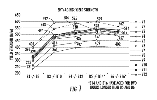
strength data and ultimate tensile data are also depicted in Figure 1 and
Figure 2, respectively.
Table 11
Aging YS UTS U.E TE CFS n- r-
Alloy Variant (MPa) (MPa) (%) (%) (%) Value Value
______________ B1 304.8 463.9 20.2 21.3 12.6 0.26
0.60
133 473.2 539.9 15.4 19.6 13.1 0.14 0.58
VI 134 517.8 , 544.9 8.8 13.8 12.5 -
B5 509.4 526.3 7.6 12.8 16.5 - - .
B6 489.5 513.8 8.2 13.7 18.4 - -
131 332.8 497.1 20.3 21.7 12.4 0.24 0.49
B3 489.9 569.4 14.0 __ 17.5 ____ 10.1 0.14 0.50
...........
......._
V2 B4 523.9 575.4 11.3 14.6 9.6 0.11
B5 533.9 , 555.9 7.9 12.7 10.7 - -
36 504.3 532.7 7.8 12.0 11.7 - - .
131 263.4 450.1 19.8 20.7 15.7 0.25 0.59
133 414.0 508.3 15.6 18.7 13.7 0.16 0.57
V3
B4 437.4 508.7 13.1 16.0 13.4 0.14 0.58
B5 456.9 512.5 10.6 14.1 14.6 -
CA 02979717 2017-09-13
WO 2017/075319
PCT/US2016/059272
86 456.8 511.0 10.2 14.1 14.4 - -
88 292.4 453.7
17.5 23.7 15.7 0.25 0.62
BIO i 465.4 542.0 14.9 17.5 13.5 0.15 0.55
V4 812 I 480.8 542.0 13.5 16.6 13.8 0.13
0.59 ,
B14 517.1 551.4 7.7 11.4 13.9 - -
B16 519.4 552.5 8.3 12.4 16.0 - -
B1 324.4 478.4 19.6 . 21.3 13.6 0.25 0.52
B3 478.3 549.7 14.3 16.6 11.0 0.14 0.55
V5 B4 504.4 552.0 11.1 14.5 11.6 0.11 -
35 541.0 566.2 7.7 11.6 12.1 - - ,
B6 ; 534.5 563.2 7.4 10.7
13.4 - .
B8 1 396.2 574.3 16.9 16.8 8.8 0.23 0.35
I
BIO ' 591.6 645.5 11.2 13.6 6.6 0.11 0.48
V6 B12 595.1 624.5 9.7 13.1 7.6 - -
B14 528.2 549.0 6.3 11.9 14.0 - -
1316 511.7 534.2 6.5 12.0 14.3 - -
138 230.8 364.7 15.1 15.3 10.9 0.23 0.45 ,
B10 361.5 438.7 13.2 14.7 10.2 0.15 0.48 .
V7 B12 s 397.5 451.6 11.3 13.8 10.8 0.12 0.50
BI4 409.4 442.5 8.4 . 12.0 14.8 - -
B16 402.1 436.2 8.5 12.5 18.9 - -
B8 309.2 464.7
18.3 21.5 12.7 0.25 0.59
810 471.8 542.3 15.2 17.8 11.1 0.14 0.66
V8 812 500.8 546.2 11.0 14.7 10.3 0.11 - .
.........._.....
B14 516.7 533.9 6.7 11.5 14.3 - -
B16 495.9 520.6 7.4 12.5 16.9 - -
138 334.4 488.5 17.4 . 18.9 10.8 0.22 0.52
B10 501.0 570.3 14.0 16.0 9.8 0.14 0.53
V9 B12 . 513.8 566.6 12.0 15.4 10.1 0.12 0.47
B14 548.7 563.1 5.8 9.2 12.6 - - .
B16 531.3 550.7 6.8 10.8 13.2 - - .
88 328.9 484.4 17.7 19.1 10.5 0.24 0.61
BIO 494.1 564.6 13.8 16.7 10.3 0.14 0.54
V1 0 B12 529.6 571.3 10.2 13.7 9.8 0.14 -
B14 529.1 547.5 7.3 10.9 12.0 - -
B16 514.4 538.2 7.5 11.8 13.7 - -
131 318.3 477.9 20.8 22.3 13.7 0.25 0.48 ,
B3 483.0 558.3 14.9 18.2 12.3 0.14 0.52
VII B4 510.6 561.7 11.3 14.6 10.8 0.11 -
B5 542.4 557.0 6.9 13.0 14.4 - -
B6 519.9 542.3 7.5 12.1 15.5 - -
26
CA 02979717 2017-09-13
WO 2017/075319 PCT1US2016/059272
B1 400.5 578.7 20.1 21.7 11.1 0.23 0.42
B3 543.3 644.7 14.1 17.8 8.9 0.14 0.42
V12 B4 584.2 643.6 11.4 15.0 8.5 0.11 0.54
135 I 598.5 618.9 7.6 11.5 9.2 - , - ,
I
Bb I 562.3 591.2 7.5 11.8 10.7 -
As shown in Table 11, significant strength increases were obtained for the
sheets
prepared from alloys V1, V2, V4, V5, V6, V7, V8, V9, V10, V11, and V12 as
compared to the
sheet prepared from alloy V3 (i.e., the AA7075 alloy used for comparative
purposes).
The highest attained yield strengths for the sheets prepared from alloys VI-
V12
according to one of the above-described aging practices (i.e., the peak age
yield strengths) are
listed in Table 12 under the heading "Peak Age Yield Strength." The change in
yield strength as
compared to the yield strength of the sheet prepared from comparative alloy
AA7075 (i.e., V3) is
also shown in Table 12. The corresponding percent total elongation (T. Elong),
percent uniform
elongation (U. Elong), and percent critical fracture strain (CFS) values are
reproduced in Table
12.
Table 12
Peak Age Yield Strength Total Uniform
Critical
Yield Change over Elongation Elongation Fracture
Strength Comparative Sheet (%) (%) Strain (%)
(MPa) (MPa)
VI 518 Increased by 61 13.8 ' 8.8 12.5
V2 534 Increased by 77 12.7 7.9 10.7
V3 457 N/A 14.1 10.6 14.6
V4 517 Increased by 60 11.4 7.7 13.9
V5 541 Increased by 84 11.6 7.7 12.1 .
V6 592 Increased by 135 13.6 11.2 6.6
. V7 409 Decreased by 48 12.0 8.4 1 14.8
I
V8 517 Increased by 60 11.5 6.7 , 14.3
V9 549 increased by 92 9.2 5.8 12.6 .
V I 0 530 Increased by 73 13.7 10.2 9.8
VI! 542 ' -----' Increased by 85 -
13.0 6.9 14.4
I
V I 2 599 Increased by 142 11.5 7.6 I 9.2
;
;
27
CA 02979717 2017-09-13
WO 2017/075319
PCT1US2016/059272
EXAMPLE 3
The sheets prepared from alloys VI through V12 were aged by heating to a
temperature
of 125 C for 24 hours. The resulting yield strengths were measured and the
results are shown in
Table 13 below. For comparative purposes, the peak age yield strengths are
also listed in Table
13.
Table 13
Peak Age Yield Yield Strength (MPa)
Strength (MPa) after aging for 24 hours at
125 C
VI 518 520
V2 534 537
V3 457 434
V4 517 503
V5 541 513
V6 592 624
V7 409 420
V8 517 523
V9 549 540
V10 530 541
VII 542 535
V12 599 579
The strength data obtained after aging for 24 hours at 125 C ("the 125 C
data") show
.. considerable variability as compared to the peak age strength data. For
example, the V6 sample
displayed a significant increase in yield strength for the 125 C data as
compared to the peak age
strength data. The V5 sample, however, showed a significant decrease in yield
strength for the
125 C data as compared to the peak age strength data. Other samples also
varied by producing
higher or lower yield strengths for the 125 C data as compared to the peak
age strength data.
.. These variations arise from the different aging kinetics of the individual
alloys. Not to be bound
by theory, the relative lower values obtained after aging at 125 C for 24
hours may have arisen
from an underaging effect
28
CA 02979717 2017-09-13
WO 2017/075319
PCT1US2016/059272
EXAMPLE 4
The tensile properties of alloys V6 and V12 were also measured in the
transverse (T)
direction according to test methods ASTM B557 and ASTM E8-11. Table 14 below
shows the
yield strength, ultimate tensile strength, percent uniform elongation, percent
tensile elongation,
and critical fracture strain for sheets prepared from alloys V6 and V12 in the
T direction. For
comparative purposes, the data values from Table 11 are reproduced for the
sheets prepared from
alloys V6 and V12 in the longitudinal (L) direction.
Table 14
Aging YS UTS n- r-
Alloy Direction Variant ( MPa) (MPa) UE (%) 'FE (%) CFS value value
B8 376.3 514.7 20.3 22.5 12.5 0.22 0.93
V6 T BI 0 551.3 587.9 10.8 14.7 9.6
B12 554.2 572.4 7.8 12.8 9.9 _____
131 385.9 533.1 21.0 23.6 13.2 0.23 0.87
V12 T 134 566.8 605.2 10.0 14.1 9.8
B5 572.9 587.7 6.5 11.1 10.4 .. -
B8 396.2 574.3 16.9 16.8 8.8 0.23 0.35
V6 L BIO 591.6 645.5 11.2 13.6 6.6 0.11 0.48
B12 595.1 624.5 9.7 13.1 7.6 - -
B1 400.5 57&7 20.1 2-177 11.1 0.23 0.42
V12 L B4 584.2 643.6 11.4 15.0 8.5 0.11 0.54
B5 598.5 618.9 7.6 11.5 9.2 -
EXAMPLE 5
Resistance spot welding was performed on sheets prepared from alloy 7075,
alloy V6,
and alloy V12 using the same parameters. See Figure 3. Specifically, a pair of
opposing
welding electrodes was brought into contact with opposite sides of sheet metal
layers at
diametrically common spots. An electrical current was then sent through the
sheet metal layers
which resulted in the forming of a molten weld pool. The current flow was
stopped and the
molten weld pool solidified into a weld nugget. The nuggets formed from the
welding in each of
the sheets had similar diameters and indentations. As shown in Figure 3,
alloys V6 and V12 had
much less columnar grain region in the weld than alloy 7075. Therefore, alloys
V6 and V12
29
CA 02979717 2017-09-13
WO 2017/075319
PCT1US2016/059272
were more crack resistant than alloy 7075, because most cracks form along the
grain boundaries
of the columnar grain region.
EXAMPLE 6
Corrosion testing was performed for alloy 7075 (two samples), alloy V6, and
alloy V12.
.. The sheets were immersed in a solution containing 57 g/L NaC1 and 10 mL
H202 for 24 hours.
As shown in Figure 4, the alloys exhibit different types and degrees of
corrosion attack. After
the 24 hour immersion period, the V6 sample exhibited the highest resistance
to intergranular
corrosion (IGC). Instead of IGC, a pitting morphology was observed in alloy
V6. See Figure 4.
The V12 sample showed some degree of IGC, but the severity was much less than
the
alloy 7075 samples. See Figure 4. In the 7075 samples, considerable
intergranular attack and
penetration in the bulk metal was observed, which demonstrates that these
samples provide the
least amount of resistance to IGC amongst the samples claimed.
The pit depths of the samples were measured using an optical microscope. The
V6
samples consistently showed the lowest average pit depth over all selected
immersion intervals,
including at 6 hours, 24 hours, and 48 hours. The average pit depth was lower
than 20 microns
and the maximum pit depth was less than 40 microns. See Figure 5.
Compared to the V6 samples, the V12 samples showed slight susceptibility to
IGC.
However, the severity was much lower than in the 7075 alloys, which showed
average pit depth
values greater than 40 microns and a maximum pit depth ranging from 75 microns
to
.. approximately 135 microns. See Figure 5.
As noted above, V6 is a low copper variant whereas V12 contains a higher
amount of
copper. Surprisingly, both the low copper variant and higher copper variant
exhibited lower
corrosion depth of attack than the baseline alloy 7075.
EXAMPLE 7
Eight alloys were prepared for strength and elongation testing (see Table 15).
Alloys
K303 K304, K305, K306, K307, K308, K309, and K311 were prepared according to
the methods
described herein. The elemental compositions of the tested alloys are shown in
Table 15, with
the balance being aluminum. The elemental compositions are provided in weight
percentages.
Each of the alloys were prepared according to the methods described herein.
CA 02979717 2017-09-13
WO 2017/075319 PCT/US2016/059272
Table 15
Alloy Si Fe Cu Mn 1 Mg Cr Zn Ti Zr
=
K303 0.10 0.14 0.14 0.01 1.56 0.00 5.45 0.02 0.16
K304 0.09 0.14 0.15 0.01 1.31 0.00 6.14 0.02 0.15
K305 0.08 0.16 0.14 0.01 1.13 0.00 6.74 0.02 0.13
K306 0.09 0.14 0.14 00! 2.08 0.00 6.30 0.03 0.14
K307 0.09 0.16 0.13 0.02 1.69 0.01 6.44 0.03 0.12
K308 0.09 0.14 0.15 0.01 1.48 0.00 7.82 0.03 0.14
K309 0.08 0.15 0.14 0.01 1.43 0.00 8.54 0.02 0.14
K310 0.11 0.16 0.13 0.00 1.35 0.00 10.00 0.025 0.14
K311 0.08 0.14 1.73 0.00 I
2.42 I 0.00 5.72 0.02 0.08
K312 0.11 0.14 1.16 0.00 1.72 0.00 7.09 0.03 0.11
K313 0.08 0.12 1.75 0.01 1.77 0.00 6.87 0.03 0.10
K314 0.12 0.12 1.87 0.00 1.54 0.00 7.51 0.03 0.08
All expressed in wt. %.
Ingots having the alloy composition shown above in Table 15 were homogenized
by
heating to about 460 C at a heating rate of about 30 Clhour. The ingots were
allowed to soak
for six hours. The ingots were then hot rolled to a final thickness of 10 mm,
using 10-11 hot
rolling passes. The exit temperatures for the hot rolling step ranged from 370
C to 380 "C. The
hot bands were immediately placed in a furnace to simulate coil cooling. The
hot bands were
then cold rolled to a final gauge thickness of approximately 1.0 ram. The cold
rolled sheets were
then heated to 460 C and allowed to soak for 60 seconds in a salt bath. The
sheets were then
quenched using water or forced air and then aged using the conditions
described below.
To reach the T4 temper, the cold rolled sheets were either held for 10 days at
room
temperature after water quenching ("14-1 Condition") or held at room
temperature for seven
days, and then heated at 70 "C for four days ("14-2 Condition"). The latter
conditions simulate a
90 day aging process at room temperature.
To reach the T6 temper, the T4 temper material was further heated to 95 'C and
allowed
to soak for eight hours, and then further heated to 145 C and soaked for 6
hours ("176-1
Condition"). Alternatively, the T6 temper was reached by holding the cold
rolled sheets for 1
day at room temperature and then further heating the sheet to 120 "C and
soaking the sheet for 24
31
CA 02979717 2017-09-13
WO 2017/075319
PCT1US2016/059272
hours ("16-2 Condition"). As a third option, the T6 temper was reached by
holding the cold
rolled sheets for 1 day at room temperature, heating the sheet to 120 C and
soaking the sheet for
1 hour, and further heating the sheet to 180 C and soaking for 30 minutes to
simulate paint bake
conditions for automotive applications ("T6-3 Condition").
The sheets were then tested for tensile properties according to ISO 6892,
bending
behavior according to VDA 238-100, and age hardening properties. Specifically,
the water
quenched sheets in 14 temper using condition T4-1 were tested for yield
strength (YS), ultimate
tensile strength (UTS), uniform elongation, total elongation, and plastic
strain ratio (referred to
as r-value or Lankford value) at angles 0 , 45 , and 90 to the rolling
direction. The data are
provided below in Table 16 and are also depicted in Figures 6-9. The copper-
free variants
showed a very anisotropic behavior, as demonstrated through the high r45
values.
Table 16
YS UTS Uniform Total Plastic
Elongation elongation strain
A80 ratio r
("elPa) (MPa) (%) (%) -
K303 0' 292 389 13.2 14.8 0.23
45 263 345 23.1 24.7 2.12
90 290 380 18.4 20.9 0.61
K304 0 313 422 16.9 16.9 0.26
45 281 377 20.0 27.0 1.79
90 313 413 17.9 18.9 0.59
K305 V 331 444 14.9 15.3 0.25
45 297 386 21.1 27.4 1.98
90 328 429 17.8 22.1 0.64
K306 0 328 436 14.7 15.8 0.27
45 301 405 22.0 24.7 1.82
90 328 429 17.9 19.0 0.57
K307 0 327 440 13.7 14.6 0.27
45 285 377 25.3 26.5 1.93
90 319 421 17.2 18.3 0.66
K308 0 329 436 13.9 14.5 0.24
32
CA 02979717 2017-09-13
WO 2017/075319
PCT1US2016/059272
450 297 385 21.8 26.4 2.03
90 326 418 16.3 21.2 0.62
1309 00 374 488 15.7 16.1 0.27
450 331 427 20.0 27.0 2.06
900 371 469 16.1 20.2 0.62
K311 00 297 445 19.5 21.5 0.43
45' 293 436 22.0 25.4 0.98
90' 303 455 20.6 22.1 0.62
The sheets aged under condition 14-2 to reach the T4 temper were tested for
yield
strength (YS), total elongation, and plastic strain ratio (r-value) at angles
0 0, 45 , and 90 to the
rolling direction. The data are depicted in Figures 10 and 11. Similar to the
sheets aged under
condition 14-1, the copper-free variants showed a very anisotropic behavior as
demonstrated
through the high r45 values. The bendability was also measured, as shown in
Figure 12.
The sheets aged under the three separate T6 conditions described above were
also tested
for yield strength and total elongation. The results are shown in Figures 13
and 14.
The results showed that the copper-free variants exhibited a very anisotropic
behavior, as
demonstrated by the high r45 values. The T6 strength level for the copper free
alloys was
between 390 to 430 MPa and the T6 strength level for copper containing alloys
ranged from 450
to 460 MPa. The inclusion of copper caused an increase in T6 temper strength,
but lower
formability.
EXAMPLE 8
Eight alloys were prepared according to the methods described herein (see
Table 17).
The elemental compositions of the tested alloys are shown in Table 17, with
the balance being
aluminum. The elemental compositions are provided in weight percentages.
33
CA 02979717 2017-09-13
WO 2017/075319
PCT1US2016/059272
Table 17
Zn
Alloy Si Fe Cu Mn Mg Zn Ti Zr +Mg
+ Cu
K388 0.10 0.15 0.15 0.05 1.50 5.35 0.02 0.10 7.00
K389 0.10 0.15 0.15 005 100 4.10 0.02 0.10 5.25
K390 0.10 0.15 0.15 005 1.25 4.40 0.02 0.10 5.80
K391 0.10 0.15 0.15 005 2.00 4.05 0.02 0.10 6.20
K392 0.10 0.15 0.15 0.05 1.75 4.70 0.02 0.10 6.60
K393 0.10 0.15 0.15 005 1.20 5.60 0.02 0.10 6.95
K394 0.10 0.15 0.30 0.05 3.05 4.45 0.02 0.10 7.80
K395 0.10 0.15 0.55 0.05 3.05 4.45 0.02 0.10 8.05
All expressed in wt. %.
EXAMPLE 9
Three variants of Alloy V6 were cast and subject to identical processing
conditions for
comparison. The elemental composition of the Alloy V6 is shown in Table 4,
with the balance
being aluminum. The elemental compositions are provided in weight percentages.
The chemical
compositions of the variants of Alloy V6 that were further investigated are
presented in Table 19.
All alloys were subject to the same solutionizing treatment.
Table 19
Alloy Zn Cu Mg Fe Si Zr Mn Cr Ti
V6 8.98 0.30 2.31 0.20 0.10 0.10 0.05 0.04
0.02
V6-6 8.98 0.30 2.31 0.20 0.10 0.05 0.05 0.04
0.02
V6-7 8,98 0.30 2.31 0.20 0.10 0.15 0.05 0.04
0.02
All expressed in wt. %.
Varying the amount of Zr in the alloy alters the microstructure. Figures 15A,
15B, and
15C show the effect of Zr amount on the alloy microstructure. Alloy V6-6 (Fig.
15A, 0.05 wk %
Zr) recrystallized, and alloys V6 (Fig. 15B, 0.10 wt. % Zr) and V6-7 (Fig.
15C, 0.15 wt. % Zr)
did not recrystallize. In some cases, Zr amounts greater than 0.10 wt. % are
sufficient to inhibit
recrystallization.
34
CA 02979717 2017-09-13
WO 2017/075319
PCT1US2016/059272
EXAMPLE 10
The elemental composition of the Alloys V4 and V6 are shown in Table 4, with
the
balance being aluminum. The elemental compositions are provided in weight
percentages. The
two alloys were cast and processed similarly in the laboratory. However, the
final microstructure
of the two alloys are significantly different after solutionizing as shown in
Figure 16A and 16B.
Figure 17A shows the SEM image of alloy V4 that is completely recrystallized
while Figure 17B
is the SEM image of alloy V6 that is completely unrecrystallized after
solutionizing.
The effect of Zr on the recrystallization kinetics can be attributed to Al3Zr
dispersoids
that are formed during homogenization. The Al3Zr dispersoids can inhibit
recrystallization by
pinning the grain boundaries. However, to be effective, these Al3Zr
dispersoids should be
coherent with the matrix, small in size, high in number and uniformly
distributed throughout the
microstructure. The Al3Zr dispersoids in the recrystallized alloy V4 (for
example, those shown
in Fig. 17A) are larger (about 20 nm diameter) and more sparse. The Al3Zr
dispersoids in the
unrecrystallized alloy V6 (for example, those shown in Fig. 17B) are smaller
(about 8 nm
diameter) and higher in number density. The larger size and low number density
of the
dispersoids in alloy V4 may not sufficiently pin the grain boundaries,
allowing a high rate of
recrystallization. On the contrary, the fine, well-dispersed dispersoids in
alloy V6 can cause
extensive pinning of the grain boundaries, thus inhibiting recrystallization.
Figures 16A and 16B
exemplify the recrystallization kinetics of the alloys presented in the
micrographs in Figures 17A
and 17B. Fig. 16A shows the recrystallization that occurred after processing
and Fig. 16B shows
the inhibited recrystallization due at least in part to the Al3Zr dispersoids.
In some cases, the
Al3Zr dispersoids can have a diameter of from about 5 nm to about 50 nm (e.g.,
from about 5 nm
to about 20 nm, from about 8 nm to about 20 nm, or from about 5 nm to about 10
nm). In some
cases, the Al3Zr dispersoids can have a diameter of less than about 20 nm
(e.g., less than about
15 nm, less than about 10 nm, or less than about 8 nm). In some cases, the
Al3Zr dispersoids can
provide a unique unrecrystallized microstructure that can lead to higher
strength. For example,
in sheets comprising Al3Zr dispersoids, the sheet can have a yield strength of
greater than about
500 MPa, greater than about 525 MPa, greater than about 550 MPa, greater than
about 575 MPa,
or greater than about 600 MPa.
The size, number and distribution of Al3Zr dispersoids can significantly
affect the
recrystallization behavior in 7,coc alloys. In some cases, the size, number
and/or distribution of
CA 02979717 2017-09-13
WO 2017/075319
PCT1US2016/059272
Al3Zr dispersoids can be controlled through alloy composition and processing.
In some cases,
uniformly distributed Al3Zr dispersoids of size less than about 10 nm can
completely stop
recrystallization of a cold rolled 7x)ot alloy during standard solutionizing
treatment (for example,
430 - 500 C for 10 seconds -6 hours). Composition and processing of 7xxx
series Al alloys can
be employed to control the microstructure of the alloys. Controlling
microstructure can afford
the ability to tailor the strength and ductility in 7x)ot alloys.
EXAMPLE 11
Eight variants of alloy V6 were cast and subjected to identical processing
conditions for
strength comparison. The elemental composition of the eight variants including
Alloy V6 are
shown in Table 20, with the balance being aluminum. The elemental compositions
are provided
in weight percentages.
Table 20
Alloy Zit Cu Mg Fe Si Zr Mn Cr Ti
V6 8.98 0.30 2.31 0.20 0.10 0.10 0.05
0.04 0.02
V6-1 8.95 0.57 2.38 0A8 0.11 0.09 0.039 0.04 001
V6-2 8.95 0.88 2.34 0.22 0.12 0.09 0.044 0.04 0.01
V6-3 9.16 1.18 2.29 0.23 0.1 0.11 0.042
0.04 0.01
V6-4 8.91 1.55 2.3 0.18 0.1 0.01 0.042 0.03
0.01
V6-5 9.01 2.05 2.26 0.2 0.09 0.09 0.041 0.03 0.01
V6-6 8.94 0.27 2.29 0.19 0.09 0.04 0.04
0.04 0.01
V6-7 9.1 0.27 2.36 0.19 0.12 0.15 0.044 0.04
0.01
V6-8 9.05 0.26 2.34 0.18 0.12 0.03 0.09
0.09 001
All expressed in wt. %.
Ingots having the alloy composition shown above in Table 20 were homogenized
according to the procedures described herein using the conditions recited in
Table 5.
Specifically, the ingots were heated to 460 C or to 465 C over 8 hours and
then soaked for a
period of time, as indicated in Table 5. The first heating and soaking is
referred to as "Stage 1"
in Table 5. Optionally, the ingots were further heated and soaked for a period
of time in a
second homogenization step, which is referred to as "Stage 2" in Table 5.
The ingots were then hot rolled from an initial thickness of 65 mm to a final
thickness of
8 mm, using 14 hot rolling passes. The laydown temperatures for the hot
rolling step ranged
from 400 C to 425 C and the exit temperatures ranged from 315 C to 370 C.
The hot bands
were immediately placed in a furnace to simulate coil cooling. The hot bands
were then cold
36
CA 02979717 2017-09-13
WO 2017/075319
PCT1US2016/059272
rolled to a final gauge thickness of approximately 2 mm (overall gauge
reduction by 75 %). The
cold rolled sheets were then heated to 465 C at a rate of approximately 283
C per hour and
allowed to soak for 1 hour. The sheets were then cooled to room temperature
(approximately 25
C) in a quenching step by using cold water or warm water and then aged.
Specifically, the alloys were quenched using water at approximately 55 C
(referred to in
this example as the "warm water quench"). For the warm water quench, the sheet
was cooled at
a rate of approximately 150 C per second to 350 C per second. The sheets
prepared from
alloys V6-1 through V6-8 were aged by heating to a temperature of 125 'V for
24 hours (referred
to in this example as the "16" temper). The resulting yield strengths measured
in longitudinal
directions are shown in Table 21 below. For comparative purposes, the yield
strength of alloy
V6 (shown in Table 13) are also listed in Table 21. The T6 temper alloys were
further aged by
heating to a temperature of 180 C for 0.5 hour (referred to in this example as
the "paint bake" or
"PB" condition). The resulting yield strength after T6+PB treatment are also
presented in Table
21.
Table 21
Alloy Yield Strength (MPa) Yield Strength
Change in Yield Strength
after aging for 24 hours (MPa) after T6+PB after PB (MPa)
at 125 C (T6)
V6 624 547 -77
V6-1 570 541 -29
V6-2 560 566 6
T3 623 597 _________________ -/6
V6-4 578 576 -4
V6-5 571 581 10
V6-6 546 520 -26
V6-7 630 544 -86
V6-8 593 543 -50
As can be seen in Table 21, alloy V6 showed a high yield strength (i.e., 624
MPa) in 16
temper. However, the additional PB treatment caused a significant drop in
yield strength, i.e., by
77 MPa to 547 MPa. The eight variants discussed herein were designed to
alleviate the
.. reduction in strength after PB while still keeping the yield strength in T6
temper greater than
37
CA 02979717 2017-09-13
WO 2017/075319
PCT1US2016/059272
about 600 MPa. It is apparent from the results presented in Table 21 that the
alloy variant V6-3
meets this criteria, which showed a YS of 623 MPa in T6 temper and 597 MPa
after the
additional PB treatment. Alloy V6-3 had only a 26 MPa drop in yield strength
after additional
PB treatment in comparison to 77 MPa and 86 MPa drop respectively for V6 and
V6-7, the other
two alloys that had T6 strength greater than 600 MPa.
As another example, alloy V12 is an alloy (composition shown in Table 4) that
has a very
low drop in yield strength after paint baking from T6 temper. The yield
strength drops from 613
MPa in 16 temper to 605 MPa after paint baking, a drop of 8 MPa only. Such an
alloy has a
fully unrecrystallized microstructure that contributes to the high strength.
This alloy can be used
in applications requiring good fracture toughness and fatigue performance
EXAMPLE 12
The alloys discussed herein may undergo a hot forming or hot stamping process
to form
the desired parts. In the hot forming process the alloy sheet is typically
heated to a temperature
.. that is above the solutionizing temperature of the specific alloy. The
solutionizing temperature
can be in a range of approximately 400 C to approximately 600 C. After
solutionizing, the alloy
sheet is transferred to a press where it is formed into the desired shape and
cooled by the die
simultaneously. Therefore, to be able to form into complex shapes, it is
important that the alloy
has good ductility or formability at elevated temperatures. In some cases the
7>ooc alloys show a
decrease in ductility when heated above certain temperatures, for example,
Alloy 7075 as shown
in Figure 18A. In other cases, Alloy V6 shows no decrease in ductility at high
temperatures as
shown in Figure 18B, which makes the alloy more suitable for hot forming
applications.
In addition to use in the automotive sector, the alloys of the present
invention may also be
used in the aerospace and consumer electronics sectors as well. For aerospace,
the alloys can
find use in structural and non-structural applications. For structural body
parts, the structural
body parts can be for example, wings, fuselages, ailerons, rudders, elevators,
cowlings, or
supports. For non-structural body parts, the non-structural body parts can be
for example, seat
tracks, seat frames, panels, or hinges. The unrecrystallized microstructure
allows for improved
fracture toughness and fatigue performance. For consumer electronics, the
alloys of the present
invention may be used for cell phone cases, laptops, tablets, televisions,
etc.
38
CA 02979717 2017-09-13
WO 2017/075319
PCT/US2016/059272
EXAMPLE 13
In another example, ingots having the alloy composition V6-3 and V6-7 shown
above in
Table 20 were homogenized according to the procedures described herein using
the conditions
recited in Table 5. Specifically, the ingots were heated to 460 C or to 465
C over 8 hours and
then soaked for a period of time, as indicated in Table 5. The first heating
and soaking is
referred to as "Stage 1" in Table 5. Optionally, the ingots were further
heated and soaked for a
period of time in a second homogenization step, which is referred to as "Stage
2" in Table 5.
The ingots were then hot rolled from an initial thickness of 65 mm to a final
thickness of
8 mm, using 14 hot rolling passes. The laydown temperatures for the hot
rolling step ranged
from 400 C to 425 C and the exit temperatures ranged from 315 C to 370 C.
The hot bands
were immediately placed in a furnace to simulate coil cooling. The hot bands
were then cold
rolled to a final gauge thickness of approximately 2 mm (overall gauge
reduction by 75 %). The
cold rolled sheets were then heated to 465 C at a rate of approximately 283
C per hour and
allowed to soak for 1 hour. The sheets were then cooled to room temperature
(approximately 25
.. C) in a quenching step by using cold water or warm water and then aged.
Specifically, the alloys were quenched using water at approximately 55 C
(referred to in
this example as the "warm water quench"). For the warm water quench, the sheet
was cooled at
a rate of approximately 150 C per second to 350 C per second. In contrast to
Example 11, the
sheets prepared from alloys V6-3 and V6-7 in Example 13 were not aged by
heating to form a T6
temper, but instead hot formed and then directly paint baked without
undergoing T6 temper. The
V6-3 and V6-7 alloys of Example 12 were further aged by heating to a
temperature of 180 C for
0.5 hour (referred to in this example as the "paint bake" or "PB" condition).
The resulting yield
strength after PB treatment are also presented in Table 22.
Table 22
Alloy Yield Strength
(Ml'a) after PB
V6-3 580
V6-7 560
As can be seen in Tables 21 and 22, alloy V6-3 processed according to Example
13
shows a yield strength of 580 MPa after aging by heating to a temperature of
180 C for 0.5 hour
(referred to in this example as the "paint bake" or "PB" condition) directly
after hot forming
39
WO 2017/075319
PCT/US20161059272
without undergoing T6 treatment as compared to the alloy V6-3 processed
according to ,Example
II, which shows a yield strength of 597 MPa after aging the alloy to16 temper
and additional
PB treatment. Alloy V6-7 processed according to Example 13 shows a yield
strength of 560
MPa after aging by paint bake directly after hot forming without undergoing TO
treatment as
compared to the ahoy VG-7 processed according to hxample II, which shows a
yield strength of
544 MPa after acing the alloy to TO temper and additional PB treatment. As can
be seen in
Table 22, alloys V6-3 and V6-7 showed a high yield strength by conducting a
paint bake
treatment directly after hot forming without undergoing TO.
Various embodiments of the invention have been described
in fulfillment of the various objectives of the invention. It should be
recognized that these
embodiments are merely illustrative of the principles of the present
invention. Numerous
modifications and adaptations thereof will be readily apparent to those of
ordinary skill in the art
without dwarfing from the spirit and scope of the invention as defined in the
following claims.
4C.
CA 2979717 2019-02-20