Note: Descriptions are shown in the official language in which they were submitted.
CA 02979848 2017-09-14
WO 2016/154142
PCT/US2016/023474
HOLSTER
CROSS-REFERENCE TO RELATED APPLICATION
The present application claims the benefit of U.S. Provisional Patent
Application
No. 62/135,917, filed March 20, 2015. The subject matter of this application
is related to
the subject matter of commonly owned, U.S. Design Patent Application No.
29/521,233,
filed March 20, 2015, entitled "Holster", both of which are hereby
incorporated by
reference herein in their entireties.
BACKGROUND OF THE DISCLOSURE
Many users of handguns, particularly military and law enforcement personnel,
carry a handgun in a holster designed to protect the handgun and hold it
securely. Holsters
can be worn in a number of ways, such as on a belt at the waist, on the thigh,
under an
arm, or around an ankle.
Certain users of handguns must be able to quickly and easily remove the
handgun
from a holster regardless of the type of holster used. Additionally, these
users need to be
assured that, when not in use, the handgun will remain safely in the holster.
Some holsters rely solely on friction to secure the handgun in place. This
combination might not be suitable for situations where the gun/holster is
subject to a great
deal of movement because such movement could cause the handgun to lose
frictional
engagement with the holster. But such holsters can be advantageous because of
the low
time required to release and/or re-secure the handgun in the holster.
Certain other holsters include a variety of strap or flap arrangements that
prevent
the removal of the firearm from the holster while the strap or flap is in
place. With designs
that rely on this method to retain a handgun, a user must first unfasten
and/or rotate the
strap/flap before the firearm can be withdrawn. Then, to re-secure the handgun
in the
holster once the handgun has been re-holstered, the user must physically
refasten and/or
rotate the strap/flap before the firearm is securely retained within the
holster. Some users
might not prefer these designs because of the time required to release and/or
re-secure the
handgun.
1
CA 02979848 2017-09-14
WO 2016/154142
PCT/US2016/023474
SUMMARY
According to one embodiment, a holster for a weapon includes a unitary semi-
rigid
holster body defining a cavity adapted to hold the weapon, the holster body
having a
closed front, a closed rear, two closed sides extending between the front and
rear, an open
bottom, and an open top adapted to receive the weapon into the cavity. The
holster body
has an attachment area for securing a holster clip to the holster body to
secure the holster
body to an article worn or carried by a user. The holster body is constructed
of an
injection-molded thermoplastic elastomer and is constructed to friction-grip
the weapon
within the cavity. When the weapon is absent from the cavity and a compressing
force is
applied against one or both of the closed sides of the holster body, the
holster body is
constructed to compress from side-to-side by at least 30% without breaking,
the open top
being constructed to automatically return to an original uncompressed shape
when the
compressing force is removed such that the weapon can be received into the
cavity for re-
holstering.
In embodiments, the holster body comprising a unitary wall that extends
continuously, unitarily around the front, a left side, the rear, and the right
side. The holster
body having a forward peak portion extending the entirety of a top to bottom
forward
length of the holster body defining a forward sight accommodating cavity
portion for the
holster. The holster peak portion is defined by a portion of the unitary wall
comprising a
pair of angled connecting forward panelar wall portions that meet at the
forwardmost peak
of the holster, with the pair of angled connecting forward panelar wall
portions defining an
interior angle of less than 90 degrees. The pair of angled connecting forward
panelar wall
portions may each have a slight concavity extending inwardly. Rearwardly of
the pair of
angled connecting forwardly panelar portions, a pair of parallel sidewall
portions connect
to the forwardly panelar portions defining an interior handgun slide receiving
cavity and a
pair of interior wall surfaces for frictionally engaging the slide of the
handgun. The pair of
parallel sidewall portion extend from the top to the bottom of the holster
body. Rearward
of the pair of parallel wall portions is a T-shaped wall portion. The upper
legs of the T of
the T-shaped wall portion define a rearward surface for the muzzle end of the
handgun,
opposite the sight. The lower leg of the T of the T-shaped wall portion
defining a pair of
narrow parallel rearward walls. The T-shaped wall portion extending upwardly
to a pair of
trigger guard defining parallel wall portions joined by a rearward bridging
wall. A bottom
2
CA 02979848 2017-09-14
WO 2016/154142
PCT/US2016/023474
opening is defined by a continuous circular lip that joins to each of the T-
shaped wall
portion, the parallel sidewall portions, and the pair of angled connecting
forwardly panelar
portions. The continuous lip and correspondingly the bottom aperture forming a
pentagon
with rounded corners, two parallel sides, and a line of symmetry. The open top
has an top
opening sized for receiving the handgun and defined by the upper ends of the
pair of
angled connecting forward panelar wall portions, the pair of parallel side
wall portions, a
further pair of parallel side wall portions, and a Y-shaped wall portion. A
passive
retention portion configured as an elongate spring member defined by two slits
extend
from within the T-shaped wall portion to the pair of trigger guard defining
parallel wall
portions. An adjustment member may adjust the distance between the spring
member and
opposite wall portion thereby adjusting a capture tension of the trigger
guard. The spring
member may have a projection defining a detent to be positioned inside the
trigger guard
when the handgun is holstered for retention of the handgun in the holster.
According to another embodiment, a holster for a weapon includes a unitary
semi-
rigid holster body defining a cavity adapted to hold the weapon, the holster
body
comprising a closed front, a closed rear, two closed sides extending between
the front and
rear, a bottom, and an open top adapted to receive the weapon into the cavity.
The holster
body has an attachment area for securing a holster clip to the holster body to
secure the
holster body inside the waistband of a user of the weapon, and is constructed
of an
injection-molded thermoplastic polyester elastomer, the holster body being
constructed to
friction-grip the weapon within the cavity. The holster body has a Shore D
durometer in
the range of about 55 to about 70. When the weapon is absent from the cavity
and a
compressing force is applied against one or both of the closed sides of the
holster body
when the holster is inside the waistband of a user, the holster body is
constructed to
compress from side-to-side, the open top being constructed to automatically
return to an
original uncompressed shape when the compressing force is removed such that
the
weapon can be received into the cavity for re-holstering.
According to another embodiment, a holster assembly for a handgun includes a
one-piece holster shell formed of an injection-molded polymeric semi-soft
material, the
holster shell defining a holster retainer attachment area, and a holster
retainer attached to
the holster shell for securing the holster shell to an article worn or carried
by a user of the
handgun. The holster retainer is formed of a substantially rigid material, and
defines an
3
CA 02979848 2017-09-14
WO 2016/154142
PCT/US2016/023474
aperture and a plurality of ridges extending away from the aperture, the
holster retainer
being rotatable with respect to the holster shell for securement in any
desired angular
position with respect to the holster shell. The holster assembly also includes
a fastener for
securing the holster retainer to the holster body, wherein tightening of the
fastener causing
the plurality of ridges to bite into the semi-soft material of the holster
shell and secure the
holster retainer to the holster shell.
According to another embodiment, a holster clip is for attachment to a semi-
rigid
holster body for securing the holster body to an article worn or carried by a
user of a
handgun adapted to fit in the holster body, the holster clip being formed of a
substantially
rigid material. The holster clip defines an aperture and a plurality of ridges
extending
away from the aperture, the holster clip being rotatable with respect to the
holster body for
securement in any desired angular position with respect to the holster body.
The aperture
is adapted to receive a fastener for securing the holster clip to the holster
body, and
tightening of the fastener causing the plurality of ridges to bite into the
semi-rigid material
of the holster body and secure the holster clip to the holster body.
A feature and advantage of the holster according to embodiments is that the
friction retention of the holster with the handgun and the detent on the
spring member
within the trigger guard is the only retention and such retention is adequate
for retaining
the handgun in the holster.
Other embodiments of the invention include a method of making and a method of
using a holster described herein.
Other aspects of the disclosure will be apparent to those of ordinary skill
upon
reading this disclosure, and this Summary should not be considered limiting.
BRIEF DESCRIPTION OF THE DRAWINGS
Embodiments of the invention will be described with reference to the figures,
in
which like reference numerals denote like elements, and in which:
Figure 1 shows a side perspective view of a handgun holster assembly,
according
to an embodiment of the invention;
4
CA 02979848 2017-09-14
WO 2016/154142
PCT/US2016/023474
Figure 2 shows an opposite side perspective view of the Figure 1 holster
assembly,
according to an embodiment of the invention;
Figure 3 is a perspective line drawing of the Figure 1 holster assembly
without a
handgun, according to an embodiment of the invention;
Figure 4 shows a front elevation view of the Figure 1 holster, according to an
embodiment of the invention;
Figure 5 shows a bottom view of the Figure 1 holster assembly, according to an
embodiment of the invention;
Figure 6 shows a top view of the Figure 1 holster assembly, according to an
embodiment of the invention;
Figure 7 shows a rear view of the Figure 1 holster assembly, according to an
embodiment of the invention;
Figure 8 is a top perspective view of the Figure 1 holster assembly, according
to an
embodiment of the invention;
Figure 9 is an opposite-side top perspective view of a holster body or shell
of the
Figure 8 holster assembly, according to an embodiment of the invention;
Figure 10 is a side view of a holster body showing load placement for a
testing
protocol, according to an embodiment of the invention;
Figure 11 is a side view of a holster clip useable in the Figure 1 holster
assembly,
according to an embodiment of the invention;
Figure 12 is an opposite side view of the Figure 11 holster clip, according to
an
embodiment of the invention;
Figure 13 is top view of the Figure 11 holster clip, according to an
embodiment of
the invention, the top and bottom views being substantial mirror images of
each other;
CA 02979848 2017-09-14
WO 2016/154142
PCT/US2016/023474
Figure 14 is an top or end view of the Figure 11 holster clip, according to an
embodiment of the invention;
Figures 15-18 are side perspective views of a holster adapted for a different
make
or model of handgun, according to an embodiment of the invention;
Figures 19-22 are side perspective views of a holster adapted for another
different
make or model of handgun, according to an embodiment of the invention; and
Figures 23-26 are side perspective views of a holster adapted for yet another
different make or model of handgun, according to an embodiment of the
invention.
DETAILED DESCRIPTION
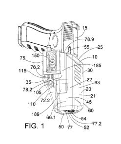
Referring to Figures 1-10, holster 10 is configured to carry handgun or other
weapon 15. Holster 10 provides Level 1 adjustable passive retention and can be
worn
inside the waistband (IWB) for concealment, according to embodiments of the
invention.
Holster 10 includes a unitary, polymeric holster shell or body 20 with a
unitary wall 21
including a pair of opposing sidewalls 22, 24 defining cavity 25 adapted to
hold handgun
15. Holster body 20 is semi-rigid and includes closed front 30, closed rear
35, first and
second closed sides 40, 45 extending between front 30 and rear 35, bottom 50,
and open
top 55 defining opening 60 adapted to receive handgun 15 within cavity 25.
Bottom 50 is
semi-closed, or partially open, defining bottom aperture 52 having
substantially rounded
corners. Aperture 52 allows debris to exit holster body 20 while still
protecting the user
from hot barrel and muzzle 54 of the handgun 15. In some cases, the width of
aperture 52
is decreased so that it is significantly less than the barrel diameter of
handgun 15, ensuring
that an extended or threaded barrel, for example, will not get stuck in
aperture 52. Bottom
50 is also substantially rounded as it transitions to front 30, rear 35, and
sides 40, 45 of
holster body 20. The rounded corners of aperture 52 and rounded transitions of
bottom 50
avoid sharp edges that might catch on clothing or create discomfort for a user
of holster
10.
The holster body 20 comprising the unitary wall 21 that extends continuously,
unitarily around the front 30, a left side 40, the rear 35, and the right side
45. The holster
body having a forward peak portion 60 extending the entirety of a top to
bottom forward
6
CA 02979848 2017-09-14
WO 2016/154142
PCT/US2016/023474
length of the holster body defining a forward sight accommodating cavity
portion 62 for
the holster. The holster peak portion is defined by a portion of the unitary
wall comprising
a pair of angled connecting forward panelar wall portions 63, 64 that meet at
the
forwardmost peak of the holster, with the pair of angled connecting forward
panelar wall
portions defining an interior angle of less than 90 degrees in embodiments.
The pair of
angled connecting forward panelar wall portions may each have a slight
concavity
extending inwardly. Rearwardly of the pair of angled connecting forwardly
panelar
portions, a pair of parallel sidewall portions 66.1, 66.2 connect to the
forwardly panelar
portions defining an interior handgun slide receiving cavity 67 and a pair of
interior wall
surfaces 68, 69 for frictionally engaging the slide of the handgun. The pair
of parallel
sidewall portions extend from the top to the bottom of the holster body.
Rearward of the
pair of parallel wall portions is a T-shaped wall portion 71. The upper legs
of the T of the
T-shaped wall portion define a rearward surface 71.2 for the muzzle end of the
handgun,
opposite the sight. The lower leg 71.4 of the T of the T-shaped wall portion
defining a
pair of narrow parallel rearward walls 72.2, 72.4. The T-shaped wall portion
extending
upwardly to a pair of trigger guard defining parallel wall portions 76.2, 76.4
joined by a
rearward bridging wall. A bottom opening 77 is defined by a continuous
circular lip 77.2
that joins to each of the T-shaped wall portion, the parallel sidewall
portions, and the pair
of angled connecting forwardly panelar portions. The continuous lip and
correspondingly
the bottom aperture forming a pentagon 77.7 with rounded corners, two parallel
sides, and
a line of symmetry. The open top has an top opening 60 sized for receiving the
handgun
and defined by the upper ends of the pair of angled connecting forward panelar
wall
portions, the pair of parallel side wall portions, a further pair of parallel
side wall portions
78.2, 78.4 , and a Y-shaped wall portion 78.7. The opening when viewed from
the side
presenting an arcuate convex upper lip 78.9 A passive retention portion 115
configured
as an elongate spring member 81 defined by two slits 81.2, 81.4 extend from
within the T-
shaped wall portion to the pair of trigger guard defining parallel wall
portions. An
adjustment member may adjust the distance between the spring member and
opposite wall
portion thereby adjusting a capture tension of the trigger guard. The spring
member may
have a projection 83, see Figure 6, defining a detent to be positioned inside
the trigger
guard when the handgun is holstered for retention of the handgun in the
holster.
Holster body 20 has one or more attachment points or areas 65, 70 for securing
holster clip 75 to holster body 20, thereby securing or connecting holster
body 20 to an
7
CA 02979848 2017-09-14
WO 2016/154142
PCT/US2016/023474
article worn or carried by a user of handgun 15. Embodiments of the invention
are used to
secure holster body 20 to a belt, for carrying holster body 20 inside the
pants or waistband,
for example. Providing two attachment points or areas on opposite sides of
holster body
20 enables attachment of clip 75 to either side, enabling ambidextrous use of
holster 10.
Holster clips may also include one or more connections to an article of
clothing or other
article at a user's chest, ankle, leg, or shoulder, for example, or to a
harness or band, or for
otherwise securing the holster to a user or the user's apparel. Clips may also
include
connections to an article carried by a user, for example a purse or bag.
Holster body 20 is constructed of an injection-molded thermoplastic elastomer
material. One such material suitable for use is sold under the HYTREL brand,
available
from DuPont, and specifically a HYTREL 6356 resin. HYTREL polyester elastomers
are
known as true thermoplastic polymers that can be processed using known
thermoplastic
techniques, and are characterized by relatively sharp melting points,
temperature-sensitive
viscosities, and generally rapid crystallization. Materials suitable for use
according to
embodiments of the invention provide one or more of strength, durability, heat
resistance,
chemical resistance, and resilience, and it should be appreciated that
materials other than
HYTREL brand materials are usable according to embodiments of the invention.
Embodiments of holster body 20 provide a Shore D durometer hardness in a range
of about 55 to about 70, more specifically of about 60 to about 65, and even
more
specifically of about 63. Such hardness values have been found to provide
holster body 20
with a semi-soft tactile effect that is comfortable to the touch, and
otherwise aesthetically
pleasing. Inside surface 80 is optionally glossier and/or smoother than
outside surface 85,
for a smoother feel and draw as handgun 15 is moved into or out of holster
body 20. To
that end, the inside of the mold core that forms the interior geometry of
cavity 25 and
inside surface 80 is not textured. Outside surface 85 of holster body 20
optionally has
more of a matte finish due to the textured mold cavities that form the
exterior geometry of
holster body 25 and outside surface 85. Thus, relative to inside surface 80 of
holster body
20, outside surface 85 has a slightly more textured feel. The relatively
smooth inside
surface, combined with the hardness ranges described above, optionally enhance
the
friction-grip effect on handgun 15 within cavity 25 when it is desired to
retain handgun 15
within holster body 20, while creating a smooth feel and draw when it is
desired to draw
or otherwise remove handgun 15. Inside surface 80 optionally has lower
coefficients of
8
CA 02979848 2017-09-14
WO 2016/154142
PCT/US2016/023474
static and/or kinetic friction than outside surface 85, or in other
embodiments, has higher
coefficients of static and/or kinetic friction than outside surface 85. The
hardness values
and ranges discussed above provide semi-rigidity to holster body 20, allowing
compressibility of holster body 20 and enabling better frictional contact with
holster clip
75.
The semi-rigidity of holster body 20 allows compression of holster body 20
from
side-to-side. When handgun 15 is within cavity 25, a compressive force acting
from
outside holster body 20 on one or more of closed sides 40, 45 compresses
inside surface
80 against the sides of handgun 15, further increasing the amount of
frictional force
holding handgun 15 within cavity 25 and reducing the likelihood of accidental
dislodgement or removal of handgun 15 from holster 10. Additionally,
embodiments of
the invention provide that when handgun 15 is absent from cavity 25 and a
compressing
force is applied against one or both of closed sides 40, 45, holster body 20
is constructed
to compress from side-to-side by at least about 30% without breaking, more
specifically at
least about 50% without breaking, still more specifically at least about 75%
without
breaking, and still more specifically about 100% without breaking.
Compressibility
percentages are established by determining an uncompressed distance between
top 90 of
first side 40 and top 95 of second side 45 at centerline 100 (Figure 10) of
holster body 20,
centerline 100 extending from top to bottom of the holster, determining a
compressed
distance between first side 40 and second side 45 at the same location,
dividing the
compressed distance by the uncompressed distance, and subtracting from 100%.
Alternatively, compressibility percentages are equivalently calculated by
subtracting
compressed distance from uncompressed distance and dividing the result by the
uncompressed distance. 100% compressibility means that first closed side 40
and second
closed side 45 come into contact with each other at the top of cavity 25.
In various embodiments, one or both of sides 40, 45 include optional slots 105
and
110, which define passive retention portion 115. Passive retention portion 115
provides
for increased frictional engagement between holster body 20 and the trigger
guard of the
handgun. Passive retention portion 115, if included, may be adjusted, via one
or more
retention screws 130 or other fasteners received in aperture 135, to provide
an adjustable
frictional tension between passive retention portion 115 and the handgun
trigger guard,
without increasing the frictional tension between a remaining portion of
holster body 20
9
CA 02979848 2017-09-14
WO 2016/154142
PCT/US2016/023474
and handgun 15. Passive retention portion 115 includes one or more stiffening
ribs 140, to
provide relatively increased rigidity or stiffness to the spring created by
passive retention
portion 115, to compensate for the semi-rigid or semi-soft nature of the
material used to
form holster body 20. Passive retention portion 115 also is of generally
increased size,
again to compensate for the nature of the material, by providing slot
extensions 142, 143
that extend generally parallel to portion 144 of rear 35 and diagonally
relative to the
remainder of slots 105, 110. Passive retention portion 115 thus provides
increased
frictional tension between passive retention portion 115 and handgun 15 inside
cavity 25.
Attachment points or areas 65, 70 for holster clip 75, according to one
embodiment, each define an aperture 145 through holster body 20, one on each
side 40, 45
to provide ambidextrous use of holster 10. The area surrounding each aperture
145 is
substantially planar and large enough to accommodate holster clip 75 in a
variety of sizes
and rotational alignments. Each aperture 145 is adapted to receive a fastener
150 for
holster clip 75. Holster body 20 defines internal recesses 155, one on each
side 40, 50,
each extending to the top of holster body 20 and each for receiving fastener
retainer 160
and substantially preventing rotation thereof within recess 155. Fastener
retainer 160 can
be inserted into and slid along recess 155 from the top of holster body 20 to
aperture 145.
Fastener 150 then is inserted through holster clip 75, into either aperture
145, and retained
by retainer 160. According to the illustrated embodiment, fastener retainer
160 is a
substantially square-shaped nut for threading onto fastener 150, which is in
the form of a
screw or bolt, for example.
Front 30 of holster body 20 includes raised portion 165 for accommodating a
sight
of handgun 15. Raised portion 165 defines a plurality of recesses, depressions
or fillets
170, 175, which simultaneously provide cosmetic features and structural
strengthening of
front 30. According to the illustrated embodiment, fillets 170 are relatively
shorter and
fillet 175 is relatively longer, to accommodate a logo or branding, for
example. Flared
areas 177 transition front 30 of holster body 20 to sides 40, 45. According to
one
embodiment, flared areas 177 extend at an angle of about 3 degrees outwardly
from sides
40, 45, to mitigate pinch and to aid in insertion of handgun 15. Additionally,
one or both
of sides 40, 45 include wider portions 180, 185 with transition areas 187, 189
to the
remainder of sides 40, 45. According to one embodiment, the transition area
extends at an
angle of about 84 degrees, which has been found advantageous in slipping
holster 10
CA 02979848 2017-09-14
WO 2016/154142
PCT/US2016/023474
inside a waistband, frictionally securing it within the waistband, and
effectively
transferring externally applied compressive force to handgun 15 when secured
within
holster 10, for example. Top 55 of holster body 20 extends high enough to
cover a
substantial portion of handgun 15, but low enough to not interfere with or
cover controls
on handgun 15, or any current or future RMR sight mounting locations. Flat
edge 190 of
top 55 optionally extends substantially parallel to the grip of handgun 15,
and adjacent
edge 192 of top 55 optionally is shaped in a way that allows the semi-rigid
material of
holster body 20 to stop on the trigger guard of handgun 15 instead of pushing
into the
trigger guard cavity when clip 75 is pushed toward inwardly toward handgun 15
or other
external compressive force is applied.
Embodiments of holster clip 75 now will be described with additional reference
to
Figures 11-14. Clip 75 includes inner mounting portion 195, outer hook portion
200, and
hook end 205. Mounting portion 195 defines two apertures 210, 215. A user of
holster 10
chooses which of apertures 210, 215 to use to connect clip 75 to attachment
point or area
65, 70 with fastener 150. Providing two apertures 210, 215 allows height
adjustment of
clip 75 with respect to holster body 20. Apertures 210, 215 are disposed at
the bottom of
recesses 220, 225 for accommodating a head of fastener 150 (Figure 1).
In addition to height adjustment with respect to holster body 20, clip 75 can
be
attached and secured to holster body 20 in an of an infinite number of angular
orientations
with respect to holster body 20. Inner surface 220 of mounting portion 195
defines a
plurality of raised ridges 225 near and extending radially outwardly from each
aperture
210, 215. The illustrated embodiment includes 12 such ridges extending
radially
outwardly, but 4, 8, or other numbers of raised ridges 225 are contemplated
according to
the disclosure. Ridges 225 also can form a square shape around apertures 201,
215 instead
of the radially outwardly or "starburst" shape or pattern. Ridges 225 provide
"bite" into
the semi-rigid or semi-soft material of holster body 20, increasing the static
friction
between holster clip 75 and holster body 20 when fastener 150 and fastener
retainer 160
are used to tighten holster clip 75 against holster body 20.
As referenced earlier herein, attachment area 65, 70 surrounding apertures 145
is
substantially planar and is large enough to accommodate holster clip 75 at any
angular
orientation with respect to holster body 20, providing infinite incremental
rotation of clip
75 relative to holster body 20. Radially extending ridges 225 serve to
effectively and
11
CA 02979848 2017-09-14
WO 2016/154142
PCT/US2016/023474
evenly engage attachment area 65 or 70 no matter what angular orientation of
clip 75 a
user chooses.
Figures 15-26 illustrate additional embodiments of the invention for
accommodating different types and styles of handgun 15. Figures 15-18
illustrate a
holster adapted for a GLOCK 19/23/32 handgun, Figures 19-22 for a GLOCK 42
handgun, and Figures 23-26 for a S&W M&P Shield handgun. Figures 1-9
illustrate a
holster adapted for a GLOCK 17/22/31 handgun, and features and advantages
described
with respect to those figures apply equally to holsters of Figures 15-20, and
vice versa. Of
course, other handguns and weapons can be held by the various holster
embodiments
described herein. Additionally, the clip of Figures 11-14 can be used with any
of the
holster embodiments referenced herein, and can be of different sizes or
proportions to fit
or be selected by a particular user. Multiple clips can be provided in
combination with
holster body 20 in a single package.
In contrast to certain prior art IWB holsters that are folded over or have a
folded-
over appearance in which sidewalls are fastened together to form an open or
openable rear
side, holster body 20 according to embodiments of the invention is of an
unfolded
configuration. No folding, folding over, or bending of holster body 20 is
needed before
holster body 20 is used to hold handgun 15 or other weapon, and holster body
20 is not
molded to have a folded appearance. Additionally, holster body 20 is unitary
and
continuous and remains permanently closed at front 30, rear 35, and both sides
40, 45.
Holster body 20 is molded as it is intended to be used, that is, it is molded
in a ready-to-
use configuration. Many such prior art IWB holsters also are formed of a rigid
material
and are subject to fracturing, breaking upon compression, whereas the semi-
rigid or semi-
soft nature of holster body 20 means that holster body 20 can be compressed
without
fracturing and will return to its original, open state for re-holstering when
compression
force is removed.
A series of tests was performed on holster embodiments according to the
invention,
to measure compressibility of each holster. An uncompressed distance between
top 90 of
first side 40 and top 95 of second side 45 at centerline 100 of holster body
20 was
measured. With reference to Figure 10, 5 pound, 7.5 pound, 10 pound, 12.5
pound, and 15
pound weighted rod assemblies were placed on-end on side 45 of holster body 20
at the
circle indicated at 250. A compressed distance between first side 40 and
second side 45 at
12
CA 02979848 2017-09-14
WO 2016/154142
PCT/US2016/023474
centerline 100 was measured, i.e. from the top points indicated at 90, 95 in
Figure 9 or
between top point 95 in Figure 10 and the corresponding top point on the
opposite side.
Compression percentages were determined by dividing the compressed distance by
the
uncompressed distance, and subtracting from 100%. Experimental data according
to
these tests are shown in Table 1 below.
IWB Holsters Compression Test Results
Holster Model Glock 17/22/31 Glock 19/23/32 Glock 42 S&W M&P
Shield
0 lbf Load (in) 1.096 0% 1.107 0% 0.950 0% 0.970 0%
lbf Load (in) 0.710 35% 0.775 30% 0.565 41% 0.512
47%
7.5 lbf Load (in) 0.520 53% 0.546 51% 0.375 61% 0.295
70%
lbf Load (in) 0.305 72% 0.365 67% 0.209 78%
0.207* 79%*
12.5 lbf Load (in) 0.080 93% 0.185 83%
0.070* 93%* 0.184* 81%*
lbf Load (in) 0.000* 100%* 0.041 96% 0.038* 96%*
0.168* 83%*
* indicates that internal features are touching, for example at passive
retention feature 115.
Table 1
For each holster embodiment, the first column is the separation distance in
inches
between sides 40 and 45, taken at holster centerline 100 between points 90,
95. The
second column is the percentage compressibility taken with respect to the
separation
distance at 0 lbf load, which represents the uncompressed distance or state.
Thus, the first
row and first two columns of data in the table indicates that the Glock
17/22/31
embodiment had an uncompressed (0% compressed) separation distance of 1.096
inches,
for example. The second row and first two columns indicate that a 5 lbf Load
applied to
the holster body compressed the holster body 20 to a separation distance of
0.710 in,
yielding a percentage compressibility of 35%. All lbf loadings, distances, and
percentages
can be considered approximate, if desired, and preceded by the word "about".
Additionally, all distances can be rounded to the nearest 100th or 10th of an
inch, i.e. 2 or
3 decimal places.
The specific testing protocol included using a 1 inch diameter steel rod
having a
weight adapter and sandpaper contact face and defining a total weight or load
of 5 lbf. A
13
CA 02979848 2017-09-14
WO 2016/154142
PCT/US2016/023474
steel outer tube was slipped over the steel rod to hold the steel rod in a
vertical or
substantially vertical orientation without affecting the load. 2.5 lb, 5 lb,
and 10 lb weights
also were provided for connection to the weight adapter. The initial,
uncompressed holster
opening or separation distance was measured using calipers at locations 90, 95
(Figs. 9-
10). Using the steel rod assembly of the steel rod, sandpaper face, and weight
adapter, the
rod end was placed tangent to the upper edge of the holster and centered with
centerline
100 of the holster, as illustrated at 250 in Fig. 10. The separation distance
at the holster
opening was measured with the calipers. The process was repeated for each
holster
embodiment and weight combination. It should be noted that in some cases, the
top
portion of holster body 20 underneath the steel rod assembly did not remain
coplanar with
the end of the rod, such that only edge or substantial-edge contact was
created between the
steel rod and the holster body at substantially the lowermost portion of the
face of the steel
rod. It should also be noted, as indicated in the table, that interior
features of holster body
20, for example passive retention portion 115 and the portion of holster body
20 opposite
it within cavity 25, were brought into contact for certain higher weight
loads.
Derived compressibility ranges for the given loads in Table 1 are shown in
Table 2,
below. All lbf loadings and ranges can be considered approximate, if desired,
and
preceded by the word "about".
Compressibility Ranges Range A Range B Range C Range D
lbf Load (in) 30% - 47% 25% - 50% 30% - 35% 40% - 50%
7.5 lbf Load (in) 51% - 70% 50% - 75% 50% - 55% 60% - 70%
lbf Load (in) 67% - 79% 65% - 80% 65% - 75% 75% - 80%
12.5 lbf Load (in) 81% - 93% 75% - 95% 80% - 95% 90% - 95%
lbf Load (in) 83% - 100% 75% - 100% 95% - 100% 90% - 100%
Table 2
Compression distances, that is, the distance that the holster is compressed,
for each
of the loads and holster embodiments in Table 1 can be readily calculated. For
the Glock
17/22/31 embodiment, for example, compression distances (in inches) of 0.386,
0.576,
0.791, 1.016, and 1.096 are calculated for lbf loads of 5, 7.5, 10, 12.5, and
15,
respectively. The following ranges of compression distances are derivable from
Table 1.
The uncompressed distance for each embodiment can be considered to be about 1
inch.
14
CA 02979848 2017-09-14
WO 2016/154142
PCT/US2016/023474
Thus, deriving ranges from the table, for an uncompressed side-to-side
separation distance
of about 1 inch: a compression load (in lbf) of about 5 yields a compression
distance (in
inches) of about 0.4, about 0.3, or about 0.5, or a range of about 0.3 to
about 0.5; a
compression load (in lbf) of about 7.5 yields a compression distance (in
inches) of about
0.6 or about 0.7, or a range of about 0.6 to about 0.7; a compression load (in
lbf) of about
yields a compression distance (in inches) of about 0.8 or about 0.7, or a
range of about
0.7 to about 0.8; a compression load (in lbf) of about 12.5 yields a
compression distance
(in inches) of about 1.0, or about 0.9, or about 0.8, or a range of about 0.8
to about 0.8 to
about 1.0; and a compression load (in lbf) of about 15 yields a compression
distance (in
inches) of about 1.0, or about 0.9, or about 0.8, or a range of about 0.8 to
about 1Ø As
previously stated herein, all lbf loadings, distances, and ranges can be
considered
approximate if needed, and preceded by the word "about". Distances and ranges
can be
derived to one, two or three decimal places.
In all cases, once compression loading on holster body 20 is removed or
released,
for example in an environment inside the waistband of a user, holster body 20
substantially or completely springs back into shape and restores the
uncompressed
distance, and restores or resumes the original shape of opening 60, allowing
handgun 15 or
other weapon to be easily reholstered without partial or complete blockage by
holster top
55 or its edges before entry of handgun 15.
It should be appreciated that, for simplicity and clarification, embodiments
of the
invention have been described with reference to a semiautomatic-type handgun
being
secured within the presently disclosed holsters. However, it should be
appreciated that
design features and operating principles of handgun holsters of this invention
may also be
employed to construct holsters or holders for any revolver or semiautomatic-
type handgun,
edged weapons, as well as less-lethal products (i.e., tasers, pepper spray,
mace canisters,
or batons). It should also be appreciated that terms such as "handgun",
"handgun holster",
and "weapon" are used for basic explanation and understanding of the operation
of the
systems, methods, and apparatuses of this invention. Such terms are not
necessarily to be
construed as limiting the systems, methods, and apparatuses of this invention.
While this invention has been described in conjunction with the exemplary
embodiments outlined above, it is evident that many alternatives,
modifications, and
variations will be apparent to those skilled in the art. Such adaptations and
modifications
CA 02979848 2017-09-14
WO 2016/154142
PCT/US2016/023474
should and are intended to be comprehended within the meaning and range of
equivalents
of the disclosed exemplary embodiments. Further, it is to be understood that
phraseology
and terminology employed herein is for the purpose of description and not of
limitation.
Accordingly, the foregoing description of the exemplary embodiments of the
invention, as
set forth above, is intended to be illustrative, not limiting. Various
changes, modifications,
and/or adaptations may be made without departing from the spirit and scope of
this
invention.
16