Note: Descriptions are shown in the official language in which they were submitted.
CA 02979849 2017-09-14
WO 2016/154169
PCT/US2016/023515
VOLTAGE BALANCING CURRENT CONTROLLED LED CIRCUIT
FIELD
100011 The present disclosure relates generally to light emitting diode
(LED) circuits.
BACKGROUND
[0002] LED lighting systems can include one or more LED devices that become
illuminated as a result of the movement of electrons through a semiconductor
material. LED
devices are becoming increasingly used in many lighting applications and have
been
integrated into a variety of products, such as light fixtures, indicator
lights, flashlights, and
other products. LED lighting systems can provide increased energy efficiency,
life and
durability, can produce less heat, and can provide other advantages relative
to traditional
incandescent and fluorescent lighting systems. Moreover, the efficiency of LED
lighting
systems has increased such that higher power can be provided at lower cost to
the consumer.
[0003] Certain LED lighting units can include multiple different types of
LEDs. For
instance, an LED lighting unit can include a first string of LEDs associated
with a first color
(e.g. wavelength) or intensity and a second string of LEDs associated with a
second color or
intensity. For instance, LED lighting units used, for instance, for
horticultural applications
can include one or more LED strings for providing a red color light (e.g.
wavelengths in the
range of about 600 nm to about 750 nm) as well as one or more LED strings
providing a blue
color light (e.g. wavelengths in the range of about 400 nm to about 500 nm).
These LED
strings can be powered by a driver current from a driver circuit. In certain
applications, the
LED strings can be coupled in parallel, for instance, to accommodate a higher
powered driver
circuit. Given the different output requirements and turn-on voltage
requirements of each of
the LED strings, coupling the LED strings in parallel can result in a voltage
imbalance in the
voltage demands for the plurality of the LED strings. And since the turn-on
voltage (e.g.
forward voltage) can be inversely proportional to the wavelength of the LED
semiconductor
material, this imbalance can be especially pronounced for parallel strings of
blue and red
LEDs. Also, LEDs of different semiconductor materials and resulting
wavelengths usually
have unequal maximum drive current ratings which can necessitate that each
parallel LED
string be driven at a different drive current.
1
SUMMARY
[0004]
Aspects and advantages of embodiments of the present disclosure will be set
forth
in part in the following description, or may be learned from the description,
or may be learned
through practice of the embodiments.
[0004a] According to the present invention, there is provided a lighting
emitting diode
(LED) circuit, comprising:
a driver circuit comprising one or more switching elements, the driver circuit
configured to provide a controlled driver current using the one or more
switching elements;
a first LED string having one or more first LED devices;
a second LED string having one or more second LED devices, the first LED
string
and the second LED string being coupled in parallel;
wherein the first LED string comprises a constant current regulator circuit
configured to provide a constant current to the first LED string such that a
balance current is
provided to the second LED string, the balance current being at least a
portion of the controlled
driver current remaining after the constant current is provided to the first
LED string.
[0004b] Preferred embodiment of the circuit are described hereunder.
[0005]
One example aspect of the present disclosure is directed to a light emitting
diode
(LED) circuit. The LED circuit can include a first LED string having one or
more first LED
devices and a second LED string having one or more second LED devices. The
first LED
string and the second LED string can be coupled in parallel. The first LED
string can include
a constant current regulator circuit configured to provide a constant current
to the first LED
string such that a balance current is provided to the second LED string. The
balance current
is at least a portion of the driver current remaining after the constant
current is provided to the
first LED string.
[0006] Another example aspect of the present disclosure is directed to a
method for
providing current to a plurality of light emitting diode (LED) devices. The
method includes
generating a driver current at a driver circuit and providing the driver
current to a plurality of
LED strings coupled in parallel. Each of the plurality of LED strings can
include a plurality
2
CA 2979849 2017-10-30
of LED devices coupled in series. The method can further include providing a
constant current
through one or more of the plurality of LED strings using one or more constant
current
regulator circuits. The method further includes providing a balance current to
one of the
plurality of LED strings. The balance current is at least a portion of the
driver current
remaining after the constant current is provided to the one or more of the
plurality of LED
strings.
[0006a] According to the present invention, there is also provided a light
emitting diode
(LED) system, comprising:
a dimmable driver circuit comprising one or more switching elements, the
dimmable driver circuit configured to provide a controlled driver current
using the one or more
switching elements;
a first LED string having one or more first LED devices;
a second LED string having one or more second LED devices, the first LED
string
and the second LED string being coupled in parallel;
wherein the first LED devices are configured to provide light at a different
color or
intensity relative to the second LED devices such that the plurality of second
LED devices of
the second LED string are associated with a greater voltage demand relative to
the plurality of
first LED devices of the first LED string;
wherein the first LED string comprises means for balancing a voltage
associated
with the first LED string and the second LED string.
[0006b] Preferred embodiments of the system are described hereunder.
[0007] Yet another example aspect of the present disclosure is directed
to a light emitting
diode (LED) system. The LED system includes a driver circuit configured to
provide a driver
current. The LED system further includes a first LED string having one or more
first LED
devices and a second LED string having one or more second LED devices. The
first LED
string and the second LED string are coupled in parallel. The first LED
devices can be
configured to provide light at a different color or intensity relative to the
second LED devices
such that the plurality of second LED devices of the second LED string are
associated with a
3
CA 2979849 2017-10-30
greater voltage demand relative to the plurality of LED devices of the first
LED string. The
first LED string includes means for balancing a voltage associated with the
first LED string
and the second LED string.
[0007a] According to the present invention, there is also provided a method
for providing
current to a plurality of light emitting diode (LED) devices, comprising:
generating a controlled driver current at a driver circuit based at least in
part on a
dimming control signal, the driver circuit comprising one or more switching
elements used to
control the controlled driver current;
providing the driver current to a plurality of LED strings coupled in
parallel, each
of the plurality of LED strings comprising a plurality of LED devices coupled
in series;
providing a constant current through one or more of the plurality of LED
strings
using one or more constant current regulator circuits;
providing a balance current to at least one of the plurality of LED strings,
the
balance current being at least a portion of the controlled driver current
remaining after the
constant current is provided to the one or more of the plurality of LED
strings.
[0007b] Preferred embodiments of the method are described hereunder
[0008] Other example aspects of the present disclosure are directed to
systems, methods,
apparatus, circuits, and electronic devices associated with LED circuits
and/or LED systems.
[0009] These and other features, aspects and advantages of various
embodiments will
become better understood with reference to the following description and
appended claims.
The accompanying drawings, which are incorporated in and constitute a part of
this
specification, illustrate embodiments of the present disclosure and, together
with the
description, serve to explain the related principles.
BRIEF DESCRIPTION OF THE DRAWINGS
[0010] Detailed discussion of embodiments directed to one of ordinary
skill in the art are
set forth in the specification, which makes reference to the appended figures,
in which:
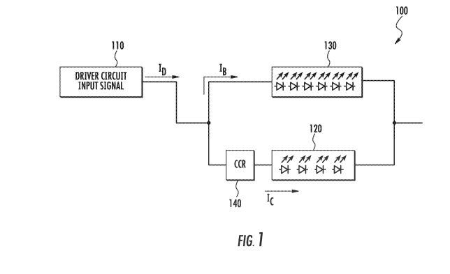
[0011] FIG. 1 depicts an example LED circuit according to example embodiments
of the
present disclosure;
3a
CA 2979849 2017-10-30
[0012] FIG. 2 depicts example LED strings coupled in parallel according
to example
embodiments of the present disclosure;
[0013] FIG. 3 depicts example LED strings coupled in parallel according
to example
embodiments of the present disclosure;
[0014] FIG. 4 depicts an example tunable constant current regulator
circuit used in
conjunction with parallel LED strings according to example embodiments of the
present
disclosure;
[0015] FIG. 5 depicts another example tunable constant current
regulator circuit used in
conjunction with parallel LED strings according to example embodiments of the
present
disclosure;
[0016] FIG. 6 depicts an example LED circuit according to example embodiments
of the
present disclosure;
[0017] FIG. 7 depicts a flow diagram of an example method for providing
current in an
LED circuit according to example embodiments of the present disclosure; and
[0018] FIG. 8 depicts an example LED lighting unit according to example
embodiments of
the present disclosure.
3b
CA 2979849 2017-10-30
CA 02979849 2017-09-14
WO 2016/154169
PCT/US2016/023515
DETAILED DESCRIPTION
[0019] Reference now will be made in detail to embodiments, one or more
examples of
which are illustrated in the drawings. Each example is provided by way of
explanation of the
embodiments, not limitation of the present disclosure. In fact, it will be
apparent to those
skilled in the art that various modifications and variations can be made to
the embodiments
without departing from the scope or spirit of the present disclosure. For
instance, features
illustrated or described as part of one embodiment can be used with another
embodiment to
yield a still further embodiment. Thus, it is intended that aspects of the
present disclosure
cover such modifications and variations.
[0020] Example aspects of the present disclosure are directed to light
emitting diode
(LED) systems having a plurality of LED devices. As used herein, a lighting
system can
include, but is not limited to, one or more of a lighting circuit, light
engine, one or more
luminaires, one or more lighting fixtures, one or more lighting units, a
plurality of lighting
devices arranged in an environment, a combination of any of the foregoing, or
other lighting
system.
[0021] LED devices can be configured to emit electromagnetic energy, for
instance, as a
result of electrons moving through a semiconductor material. The LED devices
discussed
herein can be configured to emit electromagnetic energy at a variety of ranges
of wavelengths
including across both visible and non-visible portions of the electromagnetic
spectrum. As
used herein, an LED device configured to emit light refers to an LED device
configured to
emit visible light, ultraviolet light, infrared light, and other light or
electromagnetic energy in
the electromagnetic spectrum.
[0022] According to example aspects of the present disclosure, an LED
circuit can have a
plurality LED strings coupled in parallel with one another. Each LED string
can include one
or more LED devices. For instance, an LED string can include a single LED
device, a
plurality of LED devices coupled in series, a plurality of LED devices coupled
in series with
a circuit coupled in the middle of the plurality of LED devices, a plurality
of substrings
coupled in parallel with each substring including one or more LED devices, and
other
arrangements of LED devices.
[0023] The LED strings can receive a driver current from a driver circuit
(e.g. a
dimmable driver circuit). According to example embodiments of the present
disclosure, at
least one of the plurality of LED strings can include a constant current
regulator circuit
coupled in series with the LED string. The constant current regulator circuit
can provide a
4
CA 02979849 2017-09-14
WO 2016/154169 PCT/US2016/023515
constant current through the LED string. The balance or remainder of the
driver current can
be provided to the other LED string.
[0024] In some implementations, the constant current regulator circuit can
provide
voltage balancing among the plurality of parallel LED strings. More
particularly, an LED
circuit can include a plurality of LED strings coupled in parallel, for
instance, to
accommodate an increased driver current from a higher power driver circuit.
Each of the
LED strings can be associated with differing voltage demands. More
particularly, an LED
string can have voltage demand based at least in part on the sum or aggregate
of the
individual voltage thresholds (e.g. turn-on voltages) for illuminating each of
the LED devices
coupled in series in the LED string. In certain implementations, each of the
LED strings can
be associated with a different voltage demand such that some LED strings
demand greater
voltage for operation of the LED string relative to the other LED strings. For
instance, in one
example, a first LED string can include a plurality of first LED devices
having a first turn-on
voltage (e.g. about 3.0 V) while a second LED string can include a plurality
of second LED
devices having a second turn-on voltage that is different from the first turn-
on voltage (e.g.
2.1 V). In addition, the first LED string can include a different number of
LED devices
relative to the second LED string. As a result, the first LED string can
require a greater or
lesser voltage demand for illuminating the first LED string relative to the
second LED string.
[0025] Coupling a plurality of LED strings having differing voltage demands
in parallel
can result in a voltage imbalance between the plurality of LED strings. More
particularly, an
overvoltage can be applied to an LED string having a smaller voltage demand
relative to the
other LED strings when coupling the LED strings in parallel. To balance the
difference in
voltage demands between the LED strings, a constant current regulator circuit
can be coupled
in series with at least one of the LED strings. For instance, a constant
current regulator
circuit can be coupled in an LED string having a lower voltage demand relative
to the other
LED strings. The constant current regulator circuit can be used to provide a
constant current
through the LED string while at the same time accommodating the voltage
difference
between the voltage demands of the LED strings.
[0026] The use of a constant current regulator circuit in conjunction with
one of the
plurality of LED strings according to example aspects of the present
disclosure can also
provide for the regulation of current through all of the LED strings by
actively controlling the
constant current through a only subset of the plurality of LED strings. More
particularly, in
an example where an LED circuit has two LED strings, a constant current
regulator can be
CA 02979849 2017-09-14
WO 2016/154169
PCT/US2016/023515
used to provide a constant current for one of the LED strings. The current
through the other
LED string can simply be the balance or remainder of the driver current after
providing the
constant current through the other LED string. In an example where an LED
circuit has three
LED strings, one or more constant current regulator circuits can be used to
provide a constant
current for two of the three LED strings. The current through the third LED
string can be the
balance or remainder of the driver current after providing the constant
current through the
other LED strings with their respective constant current regulators. In this
way, the current
through the all of the plurality of LED strings can be controlled without
requiring active
current control for each of the parallel LED strings. More particularly, the
current through
one of the plurality of parallel LED strings can be passively controlled
through active control
of the constant current through another parallel LED string using a constant
current regulator
circuit.
[0027] According to particular example embodiments of the present
disclosure, the
constant current regulator for at least one of the plurality of LED strings
can be a tunable
constant current regulator. A tunable constant current regulator has the
ability to change the
magnitude or amount of constant current provided to the LED string. A tunable
constant
current regulator can be used to control the amount of current provided to all
of the parallel
LED strings in an LED circuit by adjusting the constant current provided to at
least one of the
LED strings. More particularly, an adjustment in the amount of constant
current provided to
a first LED string can result in an adjustment to the amount of balance
current available for a
second LED string. In this way, a current ratio between the plurality of LED
strings can be
controlled using the tunable constant current regulator coupled in series with
one of the LED
strings.
[0028] In one particular implementation, the tunable constant current
regulator circuit can
include a resistor used to control the magnitude of the constant current. The
magnitude of the
constant current can be adjusted by changing the resistance value of the
resistor. For
instance, a resistor having a first resistance value can be replaced with a
resistor having a
second resistance value to adjust the constant current provided by the
constant current
regulator circuit.
[0029] In another particular implementation, the resistor can be a variable
resistor. The
resistance value of the variable resistor can be adjusted in a variety of
manners, for instance,
using a potentiometer, or other device. In particular implementations, the
resistance value of
the variable resistor can be adjusted based on a variable reference signal.
The variable
6
CA 02979849 2017-09-14
WO 2016/154169 PCT/US2016/023515
reference signal can be, for instance, a OV to 10V signal received from an
external circuit,
such as a dimmer circuit, smart interface control, potentiometer, Zener diode
circuit, or other
device. As used herein, a OV to by lighting control signal can vary from, for
instance, 1V to
9V, 1V to 10V, 2V to 8V, 2V to 9V, 2V, to 10V, 1V to 11V, or other suitable
range between
about OV and about by. Other suitable protocols can be used for the variable
reference
signal. For instance, the lighting control signal can be a digital addressable
lighting interface
(DALI) lighting control signal, digital multiplex (DMX) lighting control
signal, or other
control signal.
[0030] In another particular implementation, the tunable constant current
regulator circuit
can include one or more control devices, such as one or more microcontrollers,
microprocessors, logic devices, integrated circuits, or other control devices.
The control
device(s) can be powered at least in part by the driver output of the driver
circuit. The
control device(s) can control one or more switching elements (e.g.
transistors) in
communication with the LED string to control the constant current supplied to
the LED
string. For instance, a duty cycle of the switching elements can be controlled
to adjust the
constant current provided to the LED string.
[0031] The control device(s) can receive as a control input a variable
reference signal and
can control the constant current provided to the LED string based on the
variable reference
signal. As discussed above, the variable reference signal can be, for
instance, a OV to by
signal received from an external circuit, such as a dimmer circuit, smart
interface control,
potentiometer, Zener diode circuit, or other device. Other suitable protocols
can be used for
the variable reference signal, such as DALI lighting control signal, DMX
lighting control
signal, or other control signal.
[0032] With reference now to the Figures, example embodiments of the
present
disclosure will now be discussed in detail. FIG. 1 depicts an example LED
lighting circuit
100 according to example embodiments of the present disclosure. The LED
lighting circuit
100 includes a driver circuit 110 configured to provide a driver current ID to
a first LED
string 120 and a second LED string 130 coupled in parallel. The first LED
string 120 and the
second LED string 130 can each include a plurality of LED devices coupled in
series. The
LED devices can emit light as a result of electrons moving through a
semiconductor material.
The first LED string 120 and the second LED string 130 can be implemented on
the same, or
different, printed circuit board and can be associated with differing
characteristics. For
instance, the LED strings 120 and 130 can be associated with different colors,
different color
7
CA 02979849 2017-09-14
WO 2016/154169 PCT/US2016/023515
temperatures, different brightness, different lighting direction, different
intensity, or other
suitable characteristics.
[0033] In addition, the LED devices in each LED string 120 and 130 can be
uniform or
non-uniform. For instance, in some embodiments, each LED string 120 and 130
can include
a plurality of different LED devices associated with different colors,
different color
temperatures, different brightness, different lighting direction, different
intensity, or other
suitable characteristics. In other embodiments, each LED string 120 and 130
can include a
plurality of LED devices associated with the same color, color temperature,
brightness,
intensity, etc.
[0034] The driver circuit 110 can be configured to receive an input power,
such as an
input AC power or an input DC power, and can convert the input power to a
suitable driver
current ID for powering the first LED string 120 and the second LED string
130. In some
embodiments, the driver circuit 110 can include various components, such as
switching
elements (e.g. transistors) that are controlled to provide a suitable driver
current ID. For
instance, in one embodiment, the driver circuit 110 can include one or more
transistors. Gate
timing commands can be provided to the one or more transistors to convert the
input power to
a suitable driver current ID using pulse width modulation techniques. In other
instances, the
driver circuit 110 may be a direct drive AC circuit with full bridge
rectification wherein ID is
a constant Irms current.
[0035] In some example embodiments, the driver circuit 110 can be dimmable
driver
circuit. For instance, the driver circuit 110 can be a line dimming driver,
such as a phase-cut
dimmable driver, Triac dimmer, trailing edge dimmer, or other line dimming
driver. The
driver current can be adjusted using the line dimming driver by controlling
the input power to
the dimmable driver circuit. In addition and/or in the alternative, the
dimmable driver circuit
110 can receive a dimming control signal (e.g. input signal shown in FIG. 1)
used to control
the driver current. The dimming control signal can be provided from an
external circuit, such
as an external dimming circuit or sensor (e.g. an optical sensor, thermal
sensor, or other
sensor configured to provide feedback to the driver circuit for use by the
driver circuit to
adjust the driver current). The external circuit can include one or more
devices, such as a
smart dimming interface, a potentiometer, a Zener diode, or other device. The
dimming
control signal can be a OV to 10V control signal or can be implemented using
other suitable
protocols, such as a DALI protocol, or a DMX protocol.
8
CA 02979849 2017-09-14
WO 2016/154169
PCT/US2016/023515
[0036] The driver circuit 110 can be configured to adjust the driver output
based at least
in part on the dimming control signal. For example, reducing the dimming
control signal by
50% can result in a corresponding reduction in the driver current ID of about
50%. The
reduction of the driver current ID for supply to the plurality of LED strings
can result in the
radiant flux of the plurality of LED strings being simultaneously decreased.
[0037] According to particular aspects of the present disclosure, the LED
circuit 100 can
include means for balancing a voltage among the LED strings. For instance, in
some
embodiments, a constant current regulator circuit 140 can be coupled in a
series with the first
LED string 120. The constant current regulator circuit 140 can include one or
more devices
or components for providing a constant current to the first LED string 120.
For instance, as
will be discussed in more detail below, the constant current regulator circuit
140 can include
one or more regulators, resistors, electronic components, control devices, and
other
components that are configured to provide a constant current output.
[0038] As shown in FIG. 1, the constant current regulator circuit 140 is
configured to
provide a constant current Ic through the first LED string 120. A balance
current IB is
provided to the second LED string 130. The magnitude of the balance current IB
is dependent
on the constant current Ic provided by the constant current regulator circuit
140 through the
first LED string 120. For instance, the balance current IB can be the
remainder of the driver
current ID after providing the constant current Ic through the first LED
string 120.
[0039] The current provided through the first LED string 120 and the second
LED string
130 can be dependent on the output of the constant current regulator circuit
140. For
instance, if the constant current Ic output by the constant current regulator
circuit 140 is
decreased, the balance current IB can increase. Similarly, if the constant
current Ic output by
the constant current regulator circuit 140 is increases, the balance current
IB can decrease.
[0040] The constant current regulator circuit 140 can provide for voltage
balancing
between the first LED string 120 and the second LED string 130. For instance,
if the voltage
demand of the second LED string 130 is greater than the aggregated voltage
demand of the
first LED string 120, the constant current regulator circuit 140 can absorb
the voltage
difference in the voltage demands such that voltage of the first LED string
120 and the
second LED string 130 is balanced when the first LED string 120 and the second
LED string
130 are coupled in parallel.
[0041] FIG. 2 depicts a circuit diagram of one example implementation of
parallel LED
strings in an LED circuit according to example embodiments of the present
disclosure. As
9
CA 02979849 2017-09-14
WO 2016/154169 PCT/US2016/023515
shown, the first LED string 120 has a plurality of first LED devices 122
coupled in series.
The plurality of first LED devices 122 can be configured to emit light at a
particular intensity
and/or color, such as a blue color. The second LED string 130 can include a
plurality of
second LED devices 132 coupled in series. The second LED devices 132 can be
configured
to emit light at a different intensity and/or color temperature relative to
the first LED devices
122. For instance, the second LED devices 132 can be configured to emit light
at a red color.
As a result, the second LED devices 132 can be associated with different
parameters relative
to the first LED devices 122, such as different turn-on voltages.
[0042] In addition, in the example of FIG. 2, the first LED string 132
includes seven first
LED devices 122 in the first LED string 120 and twelve second LED devices 132
in the
second LED string 130. Accordingly, the second LED string 130 can require
greater voltage
requirements to drive the LEDs relative to the first LED string 120. Coupling
the first LED
string 120 in parallel with the second LED string 130 can result in a voltage
imbalance,
which can lead to an overvoltage in the first LED string 120.
[0043] To balance the voltage of the first LED string 120 and the second
LED string 130,
the first LED string 120 includes a constant current regulator circuit 140.
The constant
current regulator circuit 140 can accommodate the additional voltage and can
provide a
constant current through the first LED string 120. The example constant
current regulator
circuit 140 includes a first constant current source 142 and a second constant
current source
144 coupled in parallel. The first constant current source 142 and second
constant current
source 144 can be any suitable active current source, such as a constant
current diode, Zener
diode current source, current source having one or more transistors, op-amp
current source, or
voltage regulator current source (e.g. LM317 regulator), or other suitable
current source.
[0044] The first constant current source 142 can provide one half of the
constant current
lc through the first LED string 120 and the second constant current source 144
can provide
the other half of the constant current Ic through the first LED string 120. A
balance current
IB can be provided to the second LED string 130. The balance current IB can be
the
remainder of the driver current ID after providing the constant current Ic
through the first
LED string 120. While two constant current sources are illustrated in parallel
in FIG. 2, those
of ordinary skill in the art, using the disclosures provided herein, will
understand that more or
fewer current sources can be used in the first LED string 120 without
deviating from the
scope of the present disclosure.
CA 02979849 2017-09-14
WO 2016/154169 PCT/US2016/023515
[0045] FIG. 3 depicts a circuit diagram of another example implementation
of parallel
LED strings in an LED circuit according to example embodiments of the present
disclosure.
As shown, the first LED string 120 has a plurality of substrings 122 and 124
coupled in
parallel. Each substring 122 and 124 has a plurality of first LED devices 122
coupled in
series. Similarly, second LED string 130 has a plurality of substrings 134 and
136 coupled in
parallel. Each substring 134 and 136 has a plurality of second LED devices 132
coupled in
series. Each LED string 120 and 130 can include a plurality of substrings
coupled in parallel
to accommodate an increased driver current ID from a higher powered driver
circuit.
[0046] The substrings 124 and 126 of the first LED string 120 can be
associated with
similar voltage demands. For instance, each substring 124 and 126 can include
the same
number and same semiconductor type of LED devices 122. Similarly, the
substrings 134 and
136 of the second LED string 130 can be associated with similar voltage
demands. For
instance, each substring 134 and 136 can include the same number and same type
of LED
devices 132.
[0047] The voltage demands of the first LED string 120 and the second LED
string 130,
however, may differ as a result of being associated with a different number of
LED devices
and a different type of LED devices (e.g. with different turn-on voltages).
For instance, the
first LED string 120 can include two substrings 124, 126 each having five LED
devices 122
associated with a turn-on voltage of about 3V. The second LED string 130 can
include two
substrings 134, 136 each having ten LED devices 132 associated with a turn-on
voltage of
about 2.1 V. It will be apparent to those skilled in the art, using the
disclosure provided
herein, that the LED devices could be multiple-junction LED devices and have
higher turn-on
voltage such as about 6V, 9V, 12V, 18V, 24V, etc. Multiple-junction LED
devices can be
substituted for a comparable number of single-junction LED devices whose turn-
on voltage is
usually lower than about 3.5V As used herein, the use of the term "about" in
conjunction
with a numerical value is intended to refer to within 25% of the stated
numerical value. The
first LED devices 122 can be configured to emit light having a blue color
while the second
LED devices 132 can be configured to emit light having a red color.
[0048] To balance the voltage of the first LED string 120 and the second
LED string 130,
the first LED string 120 includes a constant current regulator circuit 140
configured to
provide a constant current Ic through the first LED string 120. The example
constant current
regulator circuit 140 illustrated in FIG. 3 includes a regulator 150 (e.g. an
LM317 regulator or
similar device) and a resistor 152. The regulator 130 can maintain a constant
voltage drop
11
CA 02979849 2017-09-14
WO 2016/154169 PCT/US2016/023515
across the resistor 152 to provide the constant current IL. The magnitude of
the voltage drop
can be selected to accommodate a difference in voltage demands between the
first LED string
120 and the second LED string 130. The magnitude of the constant current Ic
can be
dependent on the resistance value associated with the resistor 152.
[0049] In example embodiments, the constant current regulator circuit 140
of FIG. 3 can
be a tunable constant current regulator circuit that can be used to adjust the
magnitude of the
constant current Ic. For instance, the resistor 152 can be replaced or
substituted with a
different resistor having a different resistance value, causing the constant
current Ic to
increase or decrease as desired. This in turn can cause an adjustment to the
balance current IB
that is provided to the second LED string. As a result, the constant current
regulator circuit
140 can be used to control the current supplied to both the first LED string
120 and the
second LED string 130.
[0050] FIG. 4 illustrates an example circuit diagram of an example
implementation of
parallel LED strings in an LED circuit that is similar to the circuit diagram
shown in FIG. 3.
The constant current regulator circuit 140 of FIG. 4, however, includes a
variable resistor
154. The variable resistor 154 can have an adjustable resistance value.
Adjusting the
resistance value of the variable resistor 154 can adjust the constant current
Ic provided by the
constant current regulator 140 to the first LED string 120 , which can
simultaneously cause
an adjustment in the balance current IB provided to the second LED string 130.
In this way,
the current ratio between the first LED string 120 and the second LED string
130 can be
controlled by adjusting the resistance of the variable resistor 154.
[0051] The variable resistor 154 can include any suitable device for
adjusting the
resistance of the resistor 154, such as a potentiometer. In one embodiment,
the variable
resistor 154 can be coupled to a manually adjustable element (e.g. a slider,
knob, switch, etc.)
that can allow for manual adjustment of the variable resistor 154 through
movement of the
manually adjustable element. In another embodiment, the variable resistor 154
can have an
interface configured to receive a variable reference signal. The variable
reference signal can
be, for instance, a OV to by signal received from an external or internal
circuit, such as a
dimmer circuit, smart interface control, potentiometer, Zener diode circuit,
or other device.
Other suitable protocols can be used for the variable reference signal, such
as DALI lighting
control signal, DMX lighting control signal, or other control signal.
[0052] The resistance value of the variable resistor 154 can be adjusted
based on the
variable reference signal. For instance, as the variable reference signal is
adjusted from about
12
CA 02979849 2017-09-14
WO 2016/154169
PCT/US2016/023515
OV to about 5V, the resistance value of the variable resistor 154 can be
decreased causing a
corresponding increase in the constant current Ic provided by the constant
current regulator
circuit 140. This can cause a corresponding decrease in the balance current IB
provided to the
second LED string 130. In this way, the current ratio of the current provided
to the first LED
string 120 and the second LED string 130 can be controlled based at least in
part on the
variable reference signal.
[0053] FIG. 5 illustrates an example circuit diagram of an example
implementation of
parallel LED strings in an LED circuit that is similar to the circuit diagram
shown in FIG. 3.
The constant current regulator circuit 140 of FIG. 5, however, includes one or
more control
devices 160 that are configured to control one or more switching elements 162
coupled in
series with the first LED string 120 to provide a constant current Ic to the
first LED string
120.
[0054] The control device(s) 160 can include one or more devices for
controlling aspects
of the LED circuit, such as one or more microcontrollers, microprocessors,
logic devices,
integrated circuits, or other control devices. The control device(s) 160 can
control the
switching of one or more switching elements 162 coupled to the first LED
string 120. The
switching element(s) 162 can be transistors, such as MOSFET devices. Those of
ordinary
skill in the art, using the disclosures provided herein, will understand that
other switching
elements (e.g. other types of transistors) can be used without deviating from
the scope of the
present disclosure.
[0055] The control device(s) 160 can control the switching element(s) 162
by providing
gate signals to the switching element(s) 162. For instance, pulse width
modulation
techniques can be used to control the amount of constant current Ic provided
to the first LED
string. The switching element(s) 162 can be controlled at an operating
frequency that is
selected to reduce the presence of flicker in the LED strings as well as to
reduce switching
losses. For instance, in particular implementations, the switching element(s)
162 can be
operated at a frequency in the range of about 100 Hz to 1 kHz.
[0056] In particular implementations, the control device(s) 160 can control
the switching
element(s) 162 to provide a constant current Ic based on a variable reference
signal received
at an interface 164 to the control device(s) 160. The interface 164 can
include one or more
components for communicating the variable reference signal to the control
device(s) 160.
For example, the interface 164 can include one or more circuits, terminals,
pins, contacts,
13
CA 02979849 2017-09-14
WO 2016/154169
PCT/US2016/023515
conductors, or other components for communicating a variable reference signal
to the control
device(s) 160.
[0057] The variable reference signal can be, for instance, a OV to 10V
signal received
from an external or internal circuit, such as a dimmer circuit, smart
interface control,
potentiometer, Zener diode circuit, or other device. Other suitable protocols
can be used for
the variable reference signal, such as DALI lighting control signal, DMX
lighting control
signal, or other control signal.
[0058] The current ratio of the current provided to the first LED string
120 and the
second LED string 130 can be controlled based at least in part on the variable
reference
signal. For example, as the variable reference signal is adjusted from about
OV to about 5V,
the control device(s) 160 can control the switching element(s) 162 to cause an
increase in the
constant current Ic provided by the constant current regulator circuit 140 to
the first LED
string 120. This can cause a corresponding decrease in the balance current TB
provided to the
second LED string 130.
[0059] As shown in FIG. 5, the LED circuit can optionally include an
optical sensor 170
in communication with the constant current regulator circuit 140. The optical
sensor 170 can
be an ambient color sensor, light sensor, or other device configured to
monitor the radiant
flux output and/or color of the light emitted by the LED strings 120 and 130.
The optical
sensor can provide a feedback signal to the constant current regulator circuit
140. The
feedback signal can be indicative of the light output of the LED strings 120
and 130.
[0060] The control device(s) 160 can be configured to control the constant
current Ic
based at least in part on the feedback signal. For instance, if the light
output varies from a
desired light output, the control device(s) 160 can make adjustments to the
constant current Ic
provided to the first LED string 120. This can cause a corresponding change in
the balance
current IB provided to the second LED string 130 to achieve the desired light
output
[0061] The present disclosure has been discussed with reference to two LED
strings
coupled in parallel for purposes of illustration and discussion of example
embodiments of the
present disclosure. Those of ordinary skill in the art, using the disclosures
provided herein,
will understand that LED circuits according to example aspects of the present
disclosure can
include more than two LED strings coupled in parallel without deviating from
the scope of
the present disclosure.
[0062] For instance, FIG. 6 depicts an example LED circuit 200 according to
another
example embodiment of the present disclosure. The LED circuit 200 includes
three LED
14
CA 02979849 2017-09-14
WO 2016/154169
PCT/US2016/023515
strings coupled in parallel, including a first LED string 220, a second LED
string 230, and a
third LED string 240. A driver circuit 210 (e.g. a dimmable driver circuit)
can be configured
to provide a driver current ID to the plurality of LED strings. Each of the
first LED string
220, the second LED string 230, and the third LED string 240 can have
different voltage
demands as a result of the different characteristics of the LED devices used
in the respective
LED strings.
[0063] The first
LED string 220 can include a first constant current regulator circuit 222
configured to provide a constant current Ici to the first LED string 220. The
second LED
string 230 can include a second constant current regulator circuit 232
configured to provide a
constant current Ic2 to the second LED string 230. The first constant current
regulator circuit
222 and the second constant current regulator circuit 232 can be any of the
example constant
current regulator circuits disclosed herein, including a tunable constant
current regulator
circuit. A balance current TB can be provided to the third LED string 240. The
balance
current IB can be the portion of the driver current ID remaining after
providing the first
constant current Ici to the first LED string 220 and the second constant
current Ic2 to the
second LED string 230. In this way, the current provided to all of the LED
strings 220, 230,
and 240 can be controlled by actively regulating the current in a subset of
the LED strings,
namely the first LED string 220 and the second LED string 230.
[0064] FIG. 7
depicts an example method (300) for providing current in an LED circuit
according to example aspects of the present disclosure. FIG. 7 can be
implemented using any
suitable LED circuit, such any of the LED circuits illustrated in FIGS. 1-6.
In addition, FIG.
7 depicts steps performed in a particular order for purposes of illustration
and discussion.
Those of ordinary skill in the art, using the disclosures provided herein,
will understand that
various steps of any of the methods disclosed herein can be adapted, expanded,
omitted,
rearranged, or modified in various ways without deviating from the scope of
the present
disclosure.
[0065] At block
(302), the method can include generating a driver current with an LED
driver circuit. For instance, an input AC or DC power received from a power
source can be
converted by the driver circuit to a suitable driver current for powering a
plurality of LED
devices. At block (304), the driver current is provided to a plurality of LED
strings coupled
in parallel. For instance, a driver current ID can be provided to a first LED
string 120 and a
second LED string 130 (shown in FIG. 1) coupled in parallel. The first LED
string 120 can
have a different voltage demand relative to the second LED string 130.
CA 02979849 2017-09-14
WO 2016/154169 PCT/US2016/023515
[0066] At block (306), the method can include providing a constant current
through the
first LED string using a constant current regulator circuit. For instance, a
constant current
regulator circuit 140 (shown in FIG. 1) can provide a constant current lc to
the first LED
string 120. The constant current regulator circuit can also balance the
voltage associated with
the parallel LED strings such that the constant current regulator circuit
accommodates any
difference in voltage demands between the parallel LED strings.
[0067] At block (308), a balance current is provided to the second LED
string. The
balance current can be the portion of the driver current remaining after the
constant current is
provided to the first LED string. For instance, as shown in FIG. 1, the
balance current IB
provided to the second LED string 130 can be the portion of the driver current
ID remaining
after the constant current Ic is provided to the first LED string 120.
[0068] At block (310), the method can include adjusting the constant
current to the first
LED string. For instance, a tunable constant current regulator circuit 140 can
be used to
adjust the constant current lc provided to the first LED string120. The
constant current can
be adjusted, for instance, based on a variable reference signal used to adjust
a resistance
associated with the constant current regulator circuit. In addition and/or in
the alternative, the
constant current can be adjusted using one or more control devices based at
least in part on a
variable reference signal.
[0069] At block (312), the method can include adjusting the balance current
to the second
LED string based at least in part on the adjusted constant current provided by
the constant
current regulator circuit. For instance, an increase in the constant current
lc provided to the
first LED string 120 (shown in FIG. 1) can cause a corresponding decrease in
the balance
current provided 1B provided to the second LED string 130. Similarly, a
decrease in the
constant current Ic provided to the first LED string 120 can cause an increase
in the balance
current IB provided to the second LED string 130. In this way, the constant
current regulator
circuit according to example aspects of the present disclosure can be used to
balance the
voltage among the plurality of parallel LED strings as well as to control the
current ratio
among the plurality of parallel LED strings.
[0070] FIG. 8 depicts an example LED lighting unit 400 that can include an
LED circuit
according to example embodiments of the present disclosure. The LED lighting
unit 400 can
include a housing 405 used to house and protect various components of the LED
lighting
unit. The housing 405 can be constructed of any suitable material, such as
anodized
aluminum, steel, or plastic.
16
CA 02979849 2017-09-14
WO 2016/154169 PCT/US2016/023515
[0071] The LED lighting unit 400 can include a driver circuit 410 and an
LED board 420
located within the housing 405. The driver circuit 410 can be configured to
receive an input
AC or DC power from a power source and convert the input power to a driver
current for
powering a plurality of LED devices located on the LED board 420. The LED
board 420 can
be a printed circuit board including an LED circuit having parallel LED
strings according to
example embodiments of the present disclosure.
[0072] The LED lighting unit 400 can include a lens 440 and various optics
to deliver
light emitted by the LED devices on the LED board 420. The lens 440 can be,
for instance, a
glass, polycarbonate, acrylic, or silicone lens (with or without UV
protection) or other
suitable lens. As demonstrated in FIG. 8, the LED lighting unit 400 can be
suitable for
horticultural applications where the lighting unit 400 is configured to
provide light for use by
vegetation 460.
[0073] For example, the LED board 420 can include a first LED string having
a plurality
of LED devices coupled in series and configured to provide blue light (e.g
light having a
wavelength in the range of about 400 to 500 nm) at a first intensity (e.g.
about 17
micromoles). The LED board 420 can further include a second LED string having
LED
devices coupled in series and configured to provide red light (e.g. light
having a wavelength
in the range of about 600 to 750 nm) at a second intensity (e.g. about 80
micromoles).
[0074] The first LED string can be associated with a different voltage
demand relative to
the second LED string as a result of the different light output requirements
of the first LED
string and the second LED string. Accordingly, the LED circuit implemented on
LED board
420 can include a constant current regulator circuit used to balance the
voltage of the first
LED string and the second LED string as discussed with reference to the
example
embodiments of the present disclosure disclosed herein.
[0075] While the present subject matter has been described in detail with
respect to
specific example embodiments thereof, it will be appreciated that those
skilled in the art,
upon attaining an understanding of the foregoing may readily produce
alterations to,
variations of, and equivalents to such embodiments. Accordingly, the scope of
the present
disclosure is by way of example rather than by way of limitation, and the
subject disclosure
does not preclude inclusion of such modifications, variations and/or additions
to the present
subject matter as would be readily apparent to one of ordinary skill in the
art.
17